Note: Descriptions are shown in the official language in which they were submitted.
CA 03079702 2020-04-20
WO 2019/116173
PCT/IB2018/059684
PATIENT INTERFACE FOR OPHTHALMIC SURGERY
TECHNICAL FIELD
The present disclosure relates generally to ophthalmic surgery apparatuses,
and more
specifically to patient interfaces for ophthalmic surgery.
BACKGROUND
In certain kinds of ophthalmic surgery, a laser generates a pulsed laser beam
to
perform a surgical procedure, e.g., make intrastromal cuts in the cornea or
ablate tissue from
the cornea. In certain cases, the laser beam creates a photodisruption in the
cornea, which can
separate tissue, e.g., for removal. The focus of the beam in the cornea has to
be precisely
determined, e.g., within less than 5 micrometers (i.tm) in the x, y, and z
directions. A patient
interface is usually used to hold the eye in position during the procedure.
The patient
interface is typically affixed to the eye by suction to secure the eye in
place.
BRIEF SUMMARY
In certain embodiments, a patient interface apparatus for ophthalmic surgery
comprises an annular member and an evacuation conduit. The annular member has
an outer
side, an inner side, a distal side, and a proximal side. The inner side
defines an opening that
allows for a laser beam to reach a treatment region of an eye free from
reflection or
refraction. The proximal side has a contact surface shaped to affix to a
surface of the eye, and
a groove that defines a suction chamber with the surface of the eye. The
evacuation conduit is
capable of fluid communication with the suction chamber, and conducts fluid
away from the
suction chamber to affix the contact surface to the surface of the eye.
Certain embodiments may include one or more of the following features. The
patient
interface apparatus may include a deformable seal disposed outwardly from the
outer circular
side. The evacuation conduit may include a conduit coupler that attaches to a
suction device.
The evacuation conduit may include a conduit coupler that attaches to a laser
device. The
evacuation conduit may be fixed to the annular member. The patient interface
apparatus may
include a cone disposed outwardly from the distal side of the annular member.
The cone may
have a cone coupler that attaches to a laser system. The cone may include the
evacuation
1
CA 03079702 2020-04-20
WO 2019/116173
PCT/IB2018/059684
conduit. The distal side of the annular member may be shaped to receive the
cone to
removably couple the cone to the annular member.
In certain embodiments, a system for ophthalmic surgery comprises a
measurement
device and a laser system. The measurement device measures an undeformed
treatment
region of an eye, where the eye is coupled to a patient interface that leaves
the treatment
region undeformed. The laser system registers a cutting pattern in the
treatment region in
accordance with the measurement of the treatment region; directs a laser beam
through the
patient interface towards the treatment region; and controls a focus of the
laser beam to create
the cutting pattern in the treatment region.
Certain embodiments may include one or more of the following features. The
laser
system may register the cutting pattern by: identifying an undeformed feature
of the treatment
region from the measurement of the treatment region; and registering the
cutting pattern
relative to the undeformed feature. The measurement device may track movement
of the eye,
and the laser system further may adjust creation of the remaining cutting
pattern in
accordance with the movement of the eye. The undeformed feature may be a
corneal surface
feature or a corneal thickness feature.
BRIEF DESCRIPTION OF THE DRAWINGS
Embodiments of the present disclosure are described by way of example in
greater
detail with reference to the attached figures, in which:
FIGURES lA and 1B illustrate an embodiment of a system that includes a laser
system and a patient interface coupled as shown;
FIGURE 2 illustrates an embodiment of a patient interface where an evacuation
conduit is fixed to an annular member;
FIGURE 3 illustrates an embodiment of a patient interface where a cone is
attached to
an annular member and an evacuation conduit;
FIGURE 4 illustrates an embodiment of a patient interface where a cone is
removably
coupled to an annular member and an evacuation conduit; and
FIGURE 5 illustrates an example of a method for creating intrastromal cuts
that may
be performed by the system of FIGURE 1.
2
CA 03079702 2020-04-20
WO 2019/116173
PCT/IB2018/059684
DESCRIPTION OF EXAMPLE EMBODIMENTS
Referring now to the description and drawings, example embodiments of the
disclosed apparatuses, systems, and methods are shown in detail. As apparent
to a person of
ordinary skill in the field, the disclosed embodiments are exemplary and not
exhaustive of all
possible embodiments.
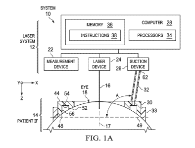
FIGURES lA and 1B illustrate an embodiment of a system 10 that includes a
laser
system 12 and a patient interface 14 coupled as shown. FIGURE 1B shows a top
view of
patient interface 14 with a line A-A that bisects interface 14, and FIGURE lA
shows a cut
away view of patient interface 14 along line A-A. In the embodiment, laser
system 12 emits a
laser beam 16 to perform a procedure on a treatment region of an eye 18 of a
human patient,
and patient interface 14 secures eye 18 in place while the procedure is being
performed.
Patient interface 14 does not deform the treatment region of eye 18 and allows
for laser beam
16 to reach the treatment region without reflection or refraction. Since the
treatment region of
eye 18 is undeformed, laser system 12 can center a treatment plan on a natural
feature of the
undeformed eye (or "undeformed feature"), such as the apex.
Laser system 12 may perform any suitable ophthalmic procedure on eye 18 that
cuts
or shapes tissue of eye 18. Examples of such procedures include ophthalmic
treatment
procedures, e.g., laser assisted in situ Keratomileusis (LASIK) (including
flap creation),
refractive lenticule extraction (ReLEx), Small Incision Lenticule Extraction
(SMILE),
photorefractive keratectomy (PRK), laser assisted sub-epithelium
keratomileusis (LASEK),
intrastromal implant insertion, and keratoplasty.
Laser system 12 includes a measurement device 22, a laser device 24, a suction
device
26, and a computer 28 coupled as shown. Measurement device 22 measures a
treatment
region of eye 18, which is generally the region where laser beam 16 is applied
during the
surgical procedure. In certain embodiments, the treatment region is the
cornea, and
measurement device 22 measures the surface topography and/or the thickness of
the cornea.
In certain embodiments, measurement device 22 may comprise an eye-tracker that
measures
the position and movement of an eye using, e.g., the surface topography and/or
thickness of
the cornea. Examples of measurement devices 22 include corneal topography,
OCT,
Scheimpflug, and projected pattern sequences (e.g., stripes) devices. When the
treatment
region of eye 18 is undeformed, the cornea has its natural topography and
thickness, allowing
measurement device 22 to measure the natural (i.e., undeformed) features of
eye 18.
3
CA 03079702 2020-04-20
WO 2019/116173
PCT/IB2018/059684
Examples of such undeformed features include topographical features of the
undeformed eye
18, e.g., the apex of the undeformed eye 18. Other examples of such undeformed
features
include the corneal thickness of the undeformed eye 18, e.g., where the cornea
of the
undeformed eye 18 has a particular thickness, such as thinnest or thickest.
Laser device 24 generates laser beam 16, which may define an xyz-coordinate
system.
The axis 17 of laser beam 16 defines the z-axis, which is normal to the xy-
plane. Examples of
laser 24 include a femtosecond laser, an ultrashort pulse laser that can emit
light in the
infrared or ultraviolet wavelength range. A femtosecond laser generates a
laser beam that can
create laser-induced optical breakdowns (LIOB s) in tissue in order to, e.g.,
create an
intrastromal cut in corneal tissue. Laser device 24 may include other
components that control
beam 40, e.g., a scanner, optical elements, and a focusing objective.
Suction device 26 draws air away from a chamber 56 (described below) of
patient
interface 14 to lower the air pressure within chamber 56 to create suction
that affixes patient
interface 14 to eye 18. The air pressure may be lowered to any suitable value,
e.g., a value in
the range of 300 to 500, 500 to 800, 800 to 1000 millibar (mbar), such as a
value in one of the
following ranges 500 to 600, 600 to 700, or 700 to 800 mbar. For example, in
certain cases,
the setpoint could be approximately 650 mbar, but any suitable setpoint may be
used (e.g., a
setpoint in one of the preceding ranges). Examples of suction device 26
include air pumps.
Computer 28 controls the operation of laser system 12, and includes processors
34
and a memory 36. Processors 34 carry out operations according to instructions
38, which are
stored in memory 36. Computer 28 can perform any suitable operations. For
example,
computer 28 may receive measurements of the treatment region from measurement
device 22
and register an intrastromal cutting pattern (e.g., align the pattern with a
real-time image of
eye 18) in accordance with the measurements. An intrastromal cutting pattern
(or "cutting
pattern") instructs laser beam 16 where to make intrastromal cuts in eye 18.
In some cases,
the pattern is calculated to yield a desired refractive correction in eye 18.
Examples of
procedures using such patterns include Small Incision Lenticule Extraction
(SMILE),
ReLEx (Refractive LEnticule Extraction), and radial keratotomy. In other
cases, the pattern
is designed to yield a cut for a particular purpose. Examples of cuts
resulting from such
patterns include a flap for a LASIK procedure, a pocket for a corneal implant,
a donor corneal
transplant extraction, or a region to receive a corneal transplant. The
cutting pattern may be
registered by identifying an undeformed feature from the measurements, and
registering the
4
CA 03079702 2020-04-20
WO 2019/116173
PCT/IB2018/059684
cutting pattern relative to the undeformed feature. For example, the cutting
pattern may be
centered directly on the feature. As another example, the cutting pattern may
be centered a
predetermined distance away from the feature in any suitable direction, such
as in the
direction of the pupil center. After registering the pattern, computer 28 then
instructs laser
device 24 to direct laser beam 16 through patient interface 14 towards the
treatment region,
and controls the focus of laser beam 16 to create the cutting pattern.
Patient interface 14 includes an annular member 30, an evacuation conduit 32,
and a
seal 33 coupled as shown. Annular member 30 has an annular shape designed to
make
contact with the anterior surface of eye 18, and evacuation conduit 32 is a
conduit designed to
allow suction device 26 to draw air away from a chamber 56 of annular member
30 to affix
annular member 30 to the anterior surface. Seal 33 prevents air from leaking
in between
annular member 30 and eye 18 in order to more securely affix annular member 30
to eye 18.
Annular member 30 has an outer side 40, an inner side 42, a distal side 44,
and a
proximal side 48. Outer side 40 is the outer circular side of annular member
30, and may
have any suitable diameter do, e.g., a value in the range of 10 to 15, 15 to
21, or 21 to 30
millimeters (mm), such as a value in the range 15 to 18, 18 to 20 (e.g.,
approximately 19
mm), or 20 to 21 mm. Inner side 42 is the inner circular side of annular
member 30, and may
have any suitable diameter di, e.g., a value in the range of 5 to 9, 9 to 15,
or 15 to 20 mm,
such as a value in the range 9 to 10, 10 to 12 (e.g., approximately 11 mm), or
12 to 15 mm.
Distal side 44 is the side of annular member 30 that is placed away from eye
18, and
proximal side 48 is the side of annular member 30 that is placed towards and
in contact with
eye 18. Annular member 30 generally defines a plane 49, e.g., the circle
formed by the points
where outer side 40 meets proximal side 48 generally defines plane 49.
In the illustrated embodiment, inner side 42 defines an opening 50 that allows
for
laser beam 16 to reach the treatment region. Opening 50 allows laser beam 16
to travel from
laser system 12 to the surface of the treatment region free from reflection or
refraction. That
is, nothing in patient interface 14 reflects, refracts, or otherwise
interferes with beam 16.
Moreover, opening 50 does not deform, or change the natural shape of, the
treatment region
of eye 18, allowing for the natural topography and/or corneal thickness of eye
18 to be
measured.
Proximal side 48 has a contact surface 52 and a groove 54. Contact surface 52
is
shaped to affix to a surface of eye 18. That is, the shape of contact surface
52 is curved to
5
CA 03079702 2020-04-20
WO 2019/116173
PCT/IB2018/059684
match the shape of the anterior portion of eye 18 that it touches. Groove 54
defines a suction
chamber 56 with the surface of eye 18 when contact surface 52 is in contact
with the surface.
Groove 54 generally follows a circular path defined by annular member 30 and
has a cross
section of any suitable size and shape. For example, the cross section may be
0.1 to 0.5, 0.5 to
4, or 4 to 8 mm (such as with a value in the range 0.5 to 1, 1 to 3, or 3 to 4
mm) in the z-
direction and 0.1 to 0.5, 0.5 to 2, or 2 to 5 mm (such as with a value in the
range 0.5 to 0.8,
0.8 to 1.2, or 1.2 to 2 mm) in a direction parallel to a radius of the
circular path defined by
annular member 30.
Contact surface 52 and groove 54, along with the suction provided by suction
device
26, allow for patient interface 14 to affix to eye 18 for the procedure. Other
patient interfaces
have an additional barrier (e.g., a contact plate) between laser system 12 and
the treatment
region. However, the additional barrier reflects and/or refracts beam 16, and
in some cases
deforms eye 18.
Evacuation conduit 32 is in fluid communication with suction chamber 56 and is
configured to conduct fluid (which may be a gas or liquid) away from suction
chamber 56 to
affix the contact surface to the surface of the eye. Evacuation conduit 32 may
be shaped like a
tube, where the longitudinal axis of the tube defines an axis 60 of evacuation
conduit 32. Axis
60 may have any suitable angle A relative to plane 49, e.g., a value in the
range of 45 to 90,
90 to 180, or 180 to 200 degrees (such as a value in the range of 90 to 120,
120 to 160, 160 to
170, or 170 to 180 degrees). Axis 60 may have any suitable angle B relative to
a tangent of
outer side 40 where conduit 32 connects to annular member 30, e.g., a value in
the range of 0
to 180 or 180 to 270 degrees (such as a value in the range of 0 to 40, 40 to
80, 80 to 100, 100
to 140, or 140 to 180 degrees). In certain embodiments, evacuation conduit 32
may have a
conduit coupler 62 that is shaped to attach to a component of laser system 12.
For example,
conduit coupler 62 may be shaped to attach to suction device 26 or to laser
device 24.
Seal 33 is disposed outwardly from outer side 40 and forms a seal to prevent
air from
leaking in between annular member 30 and eye 18 in order to more securely
affix annular
member 30 to eye 18. Seal 33 may comprise any suitable deformable material,
e.g., a
deformable, biocompatible, sterilizable material.
FIGURES 2-4 illustrate embodiments of patient interface 14. FIGURE 2
illustrates an
embodiment of patient interface 14 where evacuation conduit 32 is fixed to
annular member
30. Evacuation conduit 32 may have any suitable dimensions. For example,
length 1 and
6
CA 03079702 2020-04-20
WO 2019/116173
PCT/IB2018/059684
width w may be selected to form a convenient handle that allows a user to
grasp interface 14,
such as a length 1 within a range of 5 to 10, 10 to 50, or 50 to 100 mm and a
width w within a
range of 2 to 5, 5 to 10, or 10 to 20 mm. Axis 60 may have any suitable angle
A relative to
plane 49, e.g., an angle that yields the convenient handle. Conduit coupler 62
may attach to
laser system 12 in any suitable manner. For example, coupler 62 may have a
shape that
interlocks with a component (e.g., suction device 26 or to laser device 24) of
laser system 12.
FIGURES 3 and 4 illustrate embodiments of patient interface 14 with a cone 66.
Cone
66 has a proximate side 68, a distal side 70, and a cone coupler 72. Proximate
side 68 is
placed closer to eye 18 and distal side 70 is placed away from eye18.
Proximate side 68 is
designed to be disposed outwardly from the distal side of annular member 30
and may have a
diameter that is approximately the same as that of annular member 30. Distal
side 70 may
have any suitable diameter that may be larger than or equal to that of
proximate side 68. For
example, the diameter of distal side 70 may be sized to allow cone 66 to be
conveniently used
in system 12, e.g., sized to allow cone 66 to be coupled to system 12. Cone
coupler 72 may
be located at distal side 70 and may be shaped to attach to laser device 24.
For example, cone
coupler 72 may be shaped to interlock with a component through which laser
device 24 emits
beam 16.
FIGURE 3 illustrates an embodiment of patient interface 14 where cone 66 is
attached
to annular member 30 and evacuation conduit 32. In the embodiment, proximate
side 68 of
cone 66 is attached to the distal side of annular member 30. Evacuation
conduit 32 may be
attached to cone 66 or may be formed within the side of cone 66.
FIGURE 4 illustrates an embodiment of patient interface 14 where cone 66 is
removably coupled to annular member 30 and evacuation conduit 32. In the
embodiment, the
distal side of annular member 30 is shaped to receive proximate side 68 of
cone 66.
FIGURE 5 illustrates an example of a method for creating intrastromal cuts
that may
be performed by the system of FIGURE 1. In the example, patient interface 14
that does not
deform eye 18, so laser system 12 can register the cutting pattern using an
undeformed
feature of eye 18. The method starts at step 100, where measurement device 22
measures a
treatment region of eye 18. Eye 18 is coupled to patient interface 14 that
leaves the treatment
region undeformed.
Computer 28 of laser system 12 registers a cutting pattern in the treatment
region in
accordance with the measurement at steps 102 and 104. Computer 28 identifies
an
7
CA 03079702 2020-04-20
WO 2019/116173
PCT/IB2018/059684
undeformed feature of the treatment region from the measurement at step 102,
and registers
the cutting pattern relative to the undeformed feature at step 104. For
example, computer 28
identifies the apex of eye 18 and centers the cutting pattern at or near the
apex. As another
example, computer 28 identifies the location where the cornea of eye 18 is the
thinnest and
centers the cutting pattern at or near the location. At step 106, laser device
24 directs laser
beam 16 through patient interface 14 towards the treatment region and controls
the focus of
laser beam 16 to create the cutting pattern in the treatment region.
Measurement device 22 tracks movement of eye 18 at step 110. For example,
measurement device 22 determines the apex has translated in a distance d in a
particular
direction in the xy plane. Computer 28 adjusts creation of the remaining
cutting pattern in
accordance with the movement of the eye. For example, computer 28 realigns the
cutting
pattern to according to the translation of the apex. The method then ends.
A component of the systems and apparatuses disclosed herein may include an
interface, logic, memory, and/or other suitable element, any of which may
include hardware
and/or software. An interface can receive input, provide output, process the
input and/or
output, and/or perform other suitable operations. Logic can perform the
operations of a
component, for example, execute instructions to generate output from input.
Logic may be
encoded in memory and may perform operations when executed by a computer.
Logic may
be a processor, such as one or more computers, one or more microprocessors,
one or more
applications, and/or other logic. A memory can store information and may
comprise one or
more tangible, computer-readable, and/or computer-executable storage media.
Examples of
memory include computer memory (e.g., Random Access Memory (RAM) or Read Only
Memory (ROM)), mass storage media (e.g., a hard disk), removable storage media
(e.g., a
Compact Disk (CD) or a Digital Video Disk (DVD)), database and/or network
storage (e.g., a
server), and/or other computer-readable media. In particular embodiments,
operations of the
embodiments may be performed by one or more computer readable media storing
and/or
encoded with a computer program, software, and/or other computer-executable
instructions.
Although this disclosure has been described in terms of certain embodiments,
modifications (such as substitutions, additions, omissions, and/or other
modifications) of the
embodiments will be apparent to those skilled in the art. Accordingly,
modifications may be
made to the embodiments without departing from the scope of the invention. For
example,
modifications may be made to the systems and apparatuses disclosed herein. The
components
8
CA 03079702 2020-04-20
WO 2019/116173 PCT/IB2018/059684
of the systems and apparatuses may be integrated or separated, and the
operations of the
systems and apparatuses may be performed by more, fewer, or other components.
As another
example, modifications may be made to the methods disclosed herein. The
methods may
include more, fewer, or other steps, and the steps may be performed in any
suitable order.
9