Note: Descriptions are shown in the official language in which they were submitted.
CA 03080084 2020-04-23
WO 2019/081927 PCT/GB2018/053077
IMAGE DATA ENCODING AND DECODING
BACKGROUND
Reference to Earlier Applications
This application claims priority from GB1717684.3 filed on 27 October 2017 and
GB1809024.1 filed on 1 June 2018. The contents of both of these priority
applications are
hereby incorporated by reference.
Field
This disclosure relates to image data encoding and decoding.
-- Description of Related Art
The "background" description provided herein is for the purpose of generally
presenting
the context of the disclosure. Work of the presently named inventors, to the
extent it is
described in this background section, as well as aspects of the description
which may not
otherwise qualify as prior art at the time of filing, is neither expressly or
impliedly admitted as
prior art against the present disclosure.
There are several video data encoding and decoding systems which involve
transforming video data into a frequency domain representation, quantising the
frequency
domain coefficients and then applying some form of entropy encoding to the
quantised
coefficients. This can achieve compression of the video data. A corresponding
decoding or
decompression technique is applied to recover a reconstructed version of the
original video
data.
Current video codecs (coder-decoders) such as those used in H.264/M PEG-4
Advanced
Video Coding (AVC) achieve data compression primarily by only encoding the
differences
between successive video frames. These codecs use a regular array of so-called
macroblocks,
each of which is used as a region of comparison with a corresponding
macroblock in a previous
video frame, and the image region within the macroblock is then encoded
according to the
degree of motion found between the corresponding current and previous
macroblocks in the
video sequence, or between neighbouring macroblocks within a single frame of
the video
sequence.
High Efficiency Video Coding (HEVC), also known as H.265 or MPEG-H Part 2, is
a
proposed successor to H.264/MPEG-4 AVC. It is intended for HEVC to improve
video quality
and double the data compression ratio compared to H.264, and for it to be
scalable from 128 x
96 to 7680 x 4320 pixels resolution, roughly equivalent to bit rates ranging
from 128kbit/s to
800M bit/s.
SUMMARY
The present disclosure addresses or mitigates problems arising from this
processing.
1
CA 03080084 2020-04-23
WO 2019/081927
PCT/GB2018/053077
Respective aspects and features of the present disclosure are defined in the
appended
claims.
It is to be understood that both the foregoing general description and the
following
detailed description are exemplary, but are not restrictive, of the present
technology.
BRIEF DESCRIPTION OF THE DRAWINGS
A more complete appreciation of the disclosure and many of the attendant
advantages
thereof will be readily obtained as the same becomes better understood by
reference to the
following detailed description when considered in connection with the
accompanying drawings,
wherein:
Figure 1 schematically illustrates an audio/video (AN) data transmission and
reception
system using video data compression and decompression;
Figure 2 schematically illustrates a video display system using video data
decompression;
Figure 3 schematically illustrates an audio/video storage system using video
data
compression and decompression;
Figure 4 schematically illustrates a video camera using video data
compression;
Figures 5 and 6 schematically illustrate storage media;
Figure 7 provides a schematic overview of a video data compression and
decompression apparatus;
Figure 8 schematically illustrates a predictor;
Figure 9 schematically illustrates a partially-encoded image;
Figure 10 schematically illustrates a set of possible intra-prediction
directions;
Figure 11 schematically illustrates a set of prediction modes;
Figure 12 schematically illustrates another set of prediction modes;
Figure 13 schematically illustrates an intra-prediction process;
Figures 14 and 15 schematically illustrate a reference sample projection
process;
Figure 16 schematically illustrates a predictor;
Figures 17 and 18 schematically illustrate the use of projected reference
samples;
Figure 19 schematically illustrates a prediction process;
Figures 20 to 22 schematically illustrate example interpolation techniques;
Figures 23 to 26 schematically illustrate respective groups of rows and
columns of
reference samples;
Figures 27 to 30 schematically represent respective projected versions of
Figures 23 to
26;
Figure 31 schematically represents an intra mode selector;
2
CA 03080084 2020-04-23
WO 2019/081927
PCT/GB2018/053077
Figures 32 and 33 are respective schematic flowcharts representing methods of
operation of the intra mode selector of Figure 31;
Figure 34 schematically represents an intra mode selector;
Figures 35 and 36 are respective schematic flowcharts representing methods of
operation of an intra predictor;
Figure 37 schematically illustrates a part of the functionality of an intra
predictor;
Figure 38 is a schematic flowchart representing operations of the arrangement
of Figure
37;
Figures 39 and 40 are schematic flowcharts illustrating respective methods;
Figure 41 schematically illustrates an array of coding units;
Figure 42 schematically illustrates a sample predictor;
Figures 43 and 44 schematically illustrate reference sample storage;
Figure 45 schematically represents an intra mode selector;
Figures 46 to 49 are schematic diagrams illustrating prediction processes; and
Figures 50 and 51 are schematic flowcharts illustrating respective methods.
DESCRIPTION OF THE PREFERRED EMBODIMENTS
Referring now to the drawings, Figures 1-4 are provided to give schematic
illustrations of
apparatus or systems making use of the compression and/or decompression
apparatus to be
described below in connection with embodiments of the present technology.
All of the data compression and/or decompression apparatus to be described
below may
be implemented in hardware, in software running on a general-purpose data
processing
apparatus such as a general-purpose computer, as programmable hardware such as
an
application specific integrated circuit (ASIC) or field programmable gate
array (FPGA) or as
combinations of these. In cases where the embodiments are implemented by
software and/or
firmware, it will be appreciated that such software and/or firmware, and non-
transitory data
storage media by which such software and/or firmware are stored or otherwise
provided, are
considered as embodiments of the present technology.
Figure 1 schematically illustrates an audio/video data transmission and
reception system
using video data compression and decompression.
An input audio/video signal 10 is supplied to a video data compression
apparatus 20
which compresses at least the video component of the audio/video signal 10 for
transmission
along a transmission route 30 such as a cable, an optical fibre, a wireless
link or the like. The
compressed signal is processed by a decompression apparatus 40 to provide an
output
audio/video signal 50. For the return path, a compression apparatus 60
compresses an
audio/video signal for transmission along the transmission route 30 to a
decompression
apparatus 70.
3
CA 03080084 2020-04-23
WO 2019/081927
PCT/GB2018/053077
The compression apparatus 20 and decompression apparatus 70 can therefore form
one node of a transmission link. The decompression apparatus 40 and
decompression
apparatus 60 can form another node of the transmission link. Of course, in
instances where the
transmission link is uni-directional, only one of the nodes would require a
compression
apparatus and the other node would only require a decompression apparatus.
Figure 2 schematically illustrates a video display system using video data
decompression. In particular, a compressed audio/video signal 100 is processed
by a
decompression apparatus 110 to provide a decompressed signal which can be
displayed on a
display 120. The decompression apparatus 110 could be implemented as an
integral part of the
display 120, for example being provided within the same casing as the display
device.
Alternatively, the decompression apparatus 110 maybe provided as (for example)
a so-called
set top box (STB), noting that the expression "set-top" does not imply a
requirement for the box
to be sited in any particular orientation or position with respect to the
display 120; it is simply a
term used in the art to indicate a device which is connectable to a display as
a peripheral
device.
Figure 3 schematically illustrates an audio/video storage system using video
data
compression and decompression. An input audio/video signal 130 is supplied to
a compression
apparatus 140 which generates a compressed signal for storing by a store
device 150 such as
a magnetic disk device, an optical disk device, a magnetic tape device, a
solid state storage
device such as a semiconductor memory or other storage device. For replay,
compressed data
is read from the storage device 150 and passed to a decompression apparatus
160 for
decompression to provide an output audio/video signal 170.
It will be appreciated that the compressed or encoded signal, and a storage
medium
such as a machine-readable non-transitory storage medium, storing that signal,
are considered
as embodiments of the present technology.
Figure 4 schematically illustrates a video camera using video data
compression. In
Figure 4, an image capture device 180, such as a charge coupled device (CCD)
image sensor
and associated control and read-out electronics, generates a video signal
which is passed to a
compression apparatus 190. A microphone (or plural microphones) 200 generates
an audio
signal to be passed to the compression apparatus 190. The compression
apparatus 190
generates a compressed audio/video signal 210 to be stored and/or transmitted
(shown
generically as a schematic stage 220).
The techniques to be described below relate primarily to video data
compression and
decompression. It will be appreciated that many existing techniques may be
used for audio data
compression in conjunction with the video data compression techniques which
will be
described, to generate a compressed audio/video signal. Accordingly, a
separate discussion of
audio data compression will not be provided. It will also be appreciated that
the data rate
4
CA 03080084 2020-04-23
WO 2019/081927
PCT/GB2018/053077
associated with video data, in particular broadcast quality video data, is
generally very much
higher than the data rate associated with audio data (whether compressed or
uncompressed). It
will therefore be appreciated that uncompressed audio data could accompany
compressed
video data to form a compressed audio/video signal. It will further be
appreciated that although
the present examples (shown in Figures 1-4) relate to audio/video data, the
techniques to be
described below can find use in a system which simply deals with (that is to
say, compresses,
decompresses, stores, displays and/or transmits) video data. That is to say,
the embodiments
can apply to video data compression without necessarily having any associated
audio data
handling at all.
Figure 4 therefore provides an example of a video capture apparatus comprising
an
image sensor and an encoding apparatus of the type to be discussed below.
Figure 2 therefore
provides an example of a decoding apparatus of the type to be discussed below
and a display
to which the decoded images are output.
A combination of Figure 2 and 4 may provide a video capture apparatus
comprising an
image sensor 180 and encoding apparatus 190, decoding apparatus 110 and a
display 120 to
which the decoded images are output.
Figures 5 and 6 schematically illustrate storage media, which store (for
example) the
compressed data generated by the apparatus 20, 60, the compressed data input
to the
apparatus 110 or the storage media or stages 150, 220. Figure 5 schematically
illustrates a
disc storage medium such as a magnetic or optical disc, and Figure 6
schematically illustrates a
solid state storage medium such as a flash memory. Note that Figures 5 and 6
can also
provide examples of non-transitory machine-readable storage media which store
computer
software which, when executed by a computer, causes the computer to carry out
one or more of
the methods to be discussed below.
Therefore, the above arrangements provide examples of video storage, capture,
transmission or reception apparatuses embodying any of the present techniques.
Figure 7 provides a schematic overview of a video data compression and
decompression apparatus.
A controller 343 controls the overall operation of the apparatus and, in
particular when
referring to a compression mode, controls a trial encoding processes by acting
as a selector to
select various modes of operation such as block sizes and shapes, and whether
the video data
is to be encoded losslessly or otherwise. The controller is considered to part
of the image
encoder or image decoder (as the case may be). Successive images of an input
video signal
300 are supplied to an adder 310 and to an image predictor 320. The image
predictor 320 will
be described below in more detail with reference to Figure 8. The image
encoder or decoder (as
the case may be) plus the intra-image predictor of Figure 8 may use features
from the
5
CA 03080084 2020-04-23
WO 2019/081927
PCT/GB2018/053077
apparatus of Figure 7. This does not mean that the image encoder or decoder
necessarily
requires every feature of Figure 7 however.
The adder 310 in fact performs a subtraction (negative addition) operation, in
that it
receives the input video signal 300 on a "+" input and the output of the image
predictor 320 on a
"2 input, so that the predicted image is subtracted from the input image. The
result is to
generate a so-called residual image signal 330 representing the difference
between the actual
and projected images.
One reason why a residual image signal is generated is as follows. The data
coding
techniques to be described, that is to say the techniques which will be
applied to the residual
image signal, tend to work more efficiently when there is less "energy" in the
image to be
encoded. Here, the term "efficiently" refers to the generation of a small
amount of encoded
data; for a particular image quality level, it is desirable (and considered
"efficient") to generate
as little data as is practicably possible. The reference to "energy" in the
residual image relates
to the amount of information contained in the residual image. If the predicted
image were to be
identical to the real image, the difference between the two (that is to say,
the residual image)
would contain zero information (zero energy) and would be very easy to encode
into a small
amount of encoded data. In general, if the prediction process can be made to
work reasonably
well such that the predicted image content is similar to the image content to
be encoded, the
expectation is that the residual image data will contain less information
(less energy) than the
input image and so will be easier to encode into a small amount of encoded
data.
The remainder of the apparatus acting as an encoder (to encode the residual or
difference image) will now be described. The residual image data 330 is
supplied to a
transform unit or circuitry 340 which generates a discrete cosine transform
(DOT)
representation of blocks or regions of the residual image data. The DOT
technique itself is well
known and will not be described in detail here. Note also that the use of DOT
is only illustrative
of one example arrangement. Other transforms which might be used include, for
example, the
discrete sine transform (DST). A transform could also comprise a sequence or
cascade of
individual transforms, such as an arrangement in which one transform is
followed (whether
directly or not) by another transform. The choice of transform may be
determined explicitly
and/or be dependent upon side information used to configure the encoder and
decoder.
The output of the transform unit 340, which is to say, a set of DOT
coefficients for each
transformed block of image data, is supplied to a quantiser 350. Various
quantisation
techniques are known in the field of video data compression, ranging from a
simple
multiplication by a quantisation scaling factor through to the application of
complicated lookup
tables under the control of a quantisation parameter. The general aim is
twofold. Firstly, the
quantisation process reduces the number of possible values of the transformed
data. Secondly,
the quantisation process can increase the likelihood that values of the
transformed data are
6
CA 03080084 2020-04-23
WO 2019/081927
PCT/GB2018/053077
zero. Both of these can make the entropy encoding process, to be described
below, work more
efficiently in generating small amounts of compressed video data.
A data scanning process is applied by a scan unit 360. The purpose of the
scanning
process is to reorder the quantised transformed data so as to gather as many
as possible of the
__ non-zero quantised transformed coefficients together, and of course
therefore to gather as
many as possible of the zero-valued coefficients together. These features can
allow so-called
run-length coding or similar techniques to be applied efficiently. So, the
scanning process
involves selecting coefficients from the quantised transformed data, and in
particular from a
block of coefficients corresponding to a block of image data which has been
transformed and
__ quantised, according to a "scanning order" so that (a) all of the
coefficients are selected once as
part of the scan, and (b) the scan tends to provide the desired reordering.
One example
scanning order which can tend to give useful results is a so-called up-right
diagonal scanning
order.
The scanned coefficients are then passed to an entropy encoder (EE) 370.
Again,
various types of entropy encoding may be used. Two examples are variants of
the so-called
CABAC (Context Adaptive Binary Arithmetic Coding) system and variants of the
so-called
CAVLC (Context Adaptive Variable-Length Coding) system. In general terms,
CABAC is
considered to provide a better efficiency, and in some studies has been shown
to provide a 10-
20% reduction in the quantity of encoded output data for a comparable image
quality compared
to CAVLC. However, CAVLC is considered to represent a much lower level of
complexity (in
terms of its implementation) than CABAC. Note that the scanning process and
the entropy
encoding process are shown as separate processes, but in fact can be combined
or treated
together. That is to say, the reading of data into the entropy encoder can
take place in the scan
order. Corresponding considerations apply to the respective inverse processes
to be described
below.
The output of the entropy encoder 370, along with additional data (mentioned
above
and/or discussed below), for example defining the manner in which the
predictor 320 generated
the predicted image, provides a compressed output video signal 380.
However, a return path is also provided because the operation of the predictor
320 itself
depends upon a decompressed version of the compressed output data.
The reason for this feature is as follows. At the appropriate stage in the
decompression
process (to be described below) a decompressed version of the residual data is
generated. This
decompressed residual data has to be added to a predicted image to generate an
output image
(because the original residual data was the difference between the input image
and a predicted
image). In order that this process is comparable, as between the compression
side and the
decompression side, the predicted images generated by the predictor 320 should
be the same
during the compression process and during the decompression process. Of
course, at
7
CA 03080084 2020-04-23
WO 2019/081927
PCT/GB2018/053077
decompression, the apparatus does not have access to the original input
images, but only to
the decompressed images. Therefore, at compression, the predictor 320 bases
its prediction (at
least, for inter-image encoding) on decompressed versions of the compressed
images.
The entropy encoding process carried out by the entropy encoder 370 is
considered (in
at least some examples) to be "lossless", which is to say that it can be
reversed to arrive at
exactly the same data which was first supplied to the entropy encoder 370. So,
in such
examples the return path can be implemented before the entropy encoding stage.
Indeed, the
scanning process carried out by the scan unit 360 is also considered lossless,
but in the present
embodiment the return path 390 is from the output of the quantiser 350 to the
input of a
complimentary inverse quantiser 420. In instances where loss or potential loss
is introduced by
a stage, that stage may be included in the feedback loop formed by the return
path. For
example, the entropy encoding stage can at least in principle be made lossy,
for example by
techniques in which bits are encoded within parity information. In such an
instance, the entropy
encoding and decoding should form part of the feedback loop.
In general terms, an entropy decoder 410, the reverse scan unit 400, an
inverse
quantiser 420 and an inverse transform unit or circuitry 430 provide the
respective inverse
functions of the entropy encoder 370, the scan unit 360, the quantiser 350 and
the transform
unit 340. For now, the discussion will continue through the compression
process; the process to
decompress an input compressed video signal will be discussed separately
below.
In the compression process, the scanned coefficients are passed by the return
path 390
from the quantiser 350 to the inverse quantiser 420 which carries out the
inverse operation of
the scan unit 360. An inverse quantisation and inverse transformation process
are carried out
by the units 420, 430 to generate a compressed-decompressed residual image
signal 440.
The image signal 440 is added, at an adder 450, to the output of the predictor
320 to
generate a reconstructed output image 460. This forms one input to the image
predictor 320, as
will be described below.
Turning now to the process applied to decompress a received compressed video
signal
470, the signal is supplied to the entropy decoder 410 and from there to the
chain of the reverse
scan unit 400, the inverse quantiser 420 and the inverse transform unit 430
before being added
to the output of the image predictor 320 by the adder 450. So, at the decoder
side, the decoder
reconstructs a version of the residual image and then applies this (by the
adder 450) to the
predicted version of the image (on a block by block basis) so as to decode
each block. In
straightforward terms, the output 460 of the adder 450 forms the output
decompressed video
signal 480. In practice, further filtering may optionally be applied (for
example, by a filter 560
shown in Figure 8 but omitted from Figure 7 for clarity of the higher level
diagram of Figure 7)
before the signal is output.
8
CA 03080084 2020-04-23
WO 2019/081927
PCT/GB2018/053077
The apparatus of Figures 7 and 8 can act as a compression (encoding) apparatus
or a
decompression (decoding) apparatus. The functions of the two types of
apparatus substantially
overlap. The scan unit 360 and entropy encoder 370 are not used in a
decompression mode,
and the operation of the predictor 320 (which will be described in detail
below) and other units
follow mode and parameter information contained in the received compressed bit-
stream rather
than generating such information themselves.
Figure 8 schematically illustrates the generation of predicted images, and in
particular
the operation of the image predictor 320.
There are two basic modes of prediction carried out by the image predictor
320: so-
called intra-image prediction and so-called inter-image, or motion-compensated
(MC),
prediction. At the encoder side, each involves detecting a prediction
direction in respect of a
current block to be predicted, and generating a predicted block of samples
according to other
samples (in the same (intra) or another (inter) image). By virtue of the units
310 or 450, the
difference between the predicted block and the actual block is encoded or
applied so as to
encode or decode the block respectively.
(At the decoder, or at the reverse decoding side of the encoder, the detection
of a
prediction direction may be in response to data associated with the encoded
data by the
encoder, indicating which direction was used at the encoder. Or the detection
may be in
response to the same factors as those on which the decision was made at the
encoder).
Intra-image prediction bases a prediction of the content of a block or region
of the image
on data from within the same image. This corresponds to so-called l-frame
encoding in other
video compression techniques. In contrast to l-frame encoding, however, which
involves
encoding the whole image by intra-encoding, in the present embodiments the
choice between
intra- and inter- encoding can be made on a block-by-block basis, though in
other embodiments
the choice is still made on an image-by-image basis.
Motion-compensated prediction is an example of inter-image prediction and
makes use
of motion information which attempts to define the source, in another adjacent
or nearby image,
of image detail to be encoded in the current image. Accordingly, in an ideal
example, the
contents of a block of image data in the predicted image can be encoded very
simply as a
reference (a motion vector) pointing to a corresponding block at the same or a
slightly different
position in an adjacent image.
A technique known as "block copy" prediction is in some respects a hybrid of
the two, as
it uses a vector to indicate a block of samples at a position displaced from
the currently
predicted block within the same image, which should be copied to form the
currently predicted
block.
Returning to Figure 8, two image prediction arrangements (corresponding to
intra- and
inter-image prediction) are shown, the results of which are selected by a
multiplexer 500 under
9
CA 03080084 2020-04-23
WO 2019/081927
PCT/GB2018/053077
the control of a mode signal 510 (for example, from the controller 343) so as
to provide blocks
of the predicted image for supply to the adders 310 and 450. The choice is
made in
dependence upon which selection gives the lowest "energy" (which, as discussed
above, may
be considered as information content requiring encoding), and the choice is
signalled to the
decoder within the encoded output data-stream. Image energy, in this context,
can be
detected, for example, by carrying out a trial subtraction of an area of the
two versions of the
predicted image from the input image, squaring each pixel value of the
difference image,
summing the squared values, and identifying which of the two versions gives
rise to the lower
mean squared value of the difference image relating to that image area. In
other examples, a
trial encoding can be carried out for each selection or potential selection,
with a choice then
being made according to the cost of each potential selection in terms of one
or both of the
number of bits required for encoding and distortion to the picture.
The actual prediction, in the intra-encoding system, is made on the basis of
image
blocks received as part of the signal 460, which is to say, the prediction is
based upon encoded-
decoded image blocks in order that exactly the same prediction can be made at
a
decompression apparatus. However, data can be derived from the input video
signal 300 by an
intra-mode selector 520 to control the operation of the intra-image predictor
530.
For inter-image prediction, a motion compensated (MC) predictor 540 uses
motion
information such as motion vectors derived by a motion estimator 550 from the
input video
signal 300. Those motion vectors are applied to a processed version of the
reconstructed image
460 by the motion compensated predictor 540 to generate blocks of the inter-
image prediction.
Accordingly, the units 530 and 540 (operating with the estimator 550) each act
as
detectors to detect a prediction direction in respect of a current block to be
predicted, and as a
generator to generate a predicted block of samples (forming part of the
prediction passed to the
units 310 and 450) according to other samples defined by the prediction
direction.
The processing applied to the signal 460 will now be described. Firstly, the
signal is
optionally filtered by a filter unit 560, which will be described in greater
detail below. This
involves applying a "deblocking" filter to remove or at least tend to reduce
the effects of the
block-based processing carried out by the transform unit 340 and subsequent
operations. A
sample adaptive offsetting (SAO) filter may also be used. Also, an adaptive
loop filter is
optionally applied using coefficients derived by processing the reconstructed
signal 460 and the
input video signal 300. The adaptive loop filter is a type of filter which,
using known techniques,
applies adaptive filter coefficients to the data to be filtered. That is to
say, the filter coefficients
can vary in dependence upon various factors. Data defining which filter
coefficients to use is
included as part of the encoded output data-stream.
The filtered output from the filter unit 560 in fact forms the output video
signal 480 when
the apparatus is operating as a decompression apparatus. It is also buffered
in one or more
CA 03080084 2020-04-23
WO 2019/081927
PCT/GB2018/053077
image or frame stores 570; the storage of successive images is a requirement
of motion
compensated prediction processing, and in particular the generation of motion
vectors. To save
on storage requirements, the stored images in the image stores 570 may be held
in a
compressed form and then decompressed for use in generating motion vectors.
For this
particular purpose, any known compression / decompression system may be used.
The stored
images are passed to an interpolation filter 580 which generates a higher
resolution version of
the stored images; in this example, intermediate samples (sub-samples) are
generated such
that the resolution of the interpolated image is output by the interpolation
filter 580 is 4 times (in
each dimension) that of the images stored in the image stores 570 for the
luminance channel of
4:2:0 and 8 times (in each dimension) that of the images stored in the image
stores 570 for the
chrominance channels of 4:2:0. The interpolated images are passed as an input
to the motion
estimator 550 and also to the motion compensated predictor 540.
The way in which an image is partitioned for compression processing will now
be
described. At a basic level, an image to be compressed is considered as an
array of blocks or
regions of samples. The splitting of an image into such blocks or regions can
be carried out by a
decision tree, such as that described in Bross et al: "High Efficiency Video
Coding (HEVC) text
specification draft 6", JCTVC-H1003_d0 (November 2011), the contents of which
are
incorporated herein by reference. In some examples, the resulting blocks or
regions have sizes
and, in some cases, shapes which, by virtue of the decision tree, can
generally follow the
disposition of image features within the image. This in itself can allow for
an improved encoding
efficiency because samples representing or following similar image features
would tend to be
grouped together by such an arrangement. In some examples, square blocks or
regions of
different sizes (such as 4x4 samples up to, say, 64x64 or larger blocks) are
unavailable for
selection. In other example arrangements, blocks or regions of different
shapes such as
rectangular blocks (for example, vertically or horizontally oriented) can be
used. Other non-
square and non-rectangular blocks are envisaged. The result of the division of
the image into
such blocks or regions is (in at least the present examples) that each sample
of an image is
allocated to one, and only one, such block or region.
The intra-prediction process will now be discussed. In general terms, intra-
prediction
involves generating a prediction of a current block of samples from previously-
encoded and
decoded samples in the same image.
Figure 9 schematically illustrates a partially encoded image 800. Here, the
image is
being encoded from top-left to bottom-right on a block by block basis. An
example block
encoded partway through the handling of the whole image is shown as a block
810. A shaded
region 820 above and to the left of the block 810 has already been encoded.
The intra-image
prediction of the contents of the block 810 can make use of any of the shaded
area 820 but
cannot make use of the unshaded area below that.
11
CA 03080084 2020-04-23
WO 2019/081927
PCT/GB2018/053077
In some examples, the image is encoded on a block by block basis such that
larger
blocks (referred to as coding units or CUs) are encoded in an order such as
the order discussed
with reference to Figure 9. Within each CU, there is the potential (depending
on the block
splitting process that has taken place) for the CU to be handled as a set of
two or more smaller
blocks or transform units (TUs). This can give a hierarchical order of
encoding so that the
image is encoded on a CU by CU basis, and each CU is potentially encoded on a
TU by TU
basis. Note however that for an individual TU within the current coding tree
unit (the largest
node in the tree structure of block division), the hierarchical order of
encoding (CU by CU then
TU by TU) discussed above means that there may be previously encoded samples
in the
current CU and available to the coding of that TU which are, for example,
above-right or below-
left of that TU.
The block 810 represents a CU; as discussed above, for the purposes of intra-
image
prediction processing, this may be subdivided into a set of smaller units. An
example of a
current TU 830 is shown within the CU 810. More generally, the picture is
split into regions or
groups of samples to allow efficient coding of signalling information and
transformed data. The
signalling of the information may require a different tree structure of sub-
divisions to that of the
transform, and indeed that of the prediction information or the prediction
itself. For this reason,
the coding units may have a different tree structure to that of the transform
blocks or regions,
the prediction blocks or regions and the prediction information. In some
examples such as
HEVC the structure can be a so-called quad tree of coding units, whose leaf
nodes contain one
or more prediction units and one or more transform units; the transform units
can contain
multiple transform blocks corresponding to luma and chroma representations of
the picture, and
prediction could be considered to be applicable at the transform block level.
In examples, the
parameters applied to a particular group of samples can be considered to be
predominantly
defined at a block level, which is potentially not of the same granularity as
the transform
structure.
The intra-image prediction takes into account samples coded prior to the
current TU
being considered, such as those above and/or to the left of the current TU.
Source samples,
from which the required samples are predicted, may be located at different
positions or
directions relative to the current TU. To decide which direction is
appropriate for a current
prediction unit, the mode selector 520 of an example encoder may test all
combinations of
available TU structures for each candidate direction and select the prediction
direction and TU
structure with the best compression efficiency.
The picture may also be encoded on a "slice" basis. In one example, a slice is
a
horizontally adjacent group of CUs. But in more general terms, the entire
residual image could
form a slice, or a slice could be a single CU, or a slice could be a row of
CUs, and so on. Slices
can give some resilience to errors as they are encoded as independent units.
The encoder and
12
CA 03080084 2020-04-23
WO 2019/081927
PCT/GB2018/053077
decoder states are completely reset at a slice boundary. For example, intra-
prediction is not
carried out across slice boundaries; slice boundaries are treated as image
boundaries for this
purpose.
Figure 10 schematically illustrates a set of possible (candidate) prediction
directions.
The full set of candidate directions is available to a prediction unit. The
directions are
determined by horizontal and vertical displacement relative to a current block
position, but are
encoded as prediction "modes", a set of which is shown in Figure 11. Note that
the so-called
DC mode represents a simple arithmetic mean of the surrounding upper and left-
hand samples.
Note also that the set of directions shown in Figure 10 is just one example;
in other examples, a
set of (for example) 65 angular modes plus DC and planar (a full set of 67
modes) as shown
schematically in Figure 12 makes up the full set. Other numbers of modes could
be used.
In general terms, after detecting a prediction direction, the systems are
operable to
generate a predicted block of samples according to other samples defined by
the prediction
direction. In examples, the image encoder is configured to encode data
identifying the
prediction direction selected for each sample or region of the image (and the
image decoder is
configured to detect such data).
Figure 13 schematically illustrates an intra-prediction process in which a
sample 900 of
a block or region 910 of samples is derived from other reference samples 920
of the same
image according to a direction 930 defined by the intra-prediction mode
associated with that
sample. The reference samples 920 in this example come from blocks above and
to the left of
the block 910 in question and the predicted value of the sample 900 is
obtained by tracking
along the direction 930 to the reference samples 920. The direction 930 might
point to a single
individual reference sample but in a more general case an interpolated value
between
surrounding reference samples is used as the prediction value. Note that the
block 910 could
be square as shown in Figure 13 or could be another shape such as rectangular.
Figures 14 and 15 schematically illustrate a previously proposed reference
sample
projection process.
In Figures 14 and 15, a block or region 1400 of samples to be predicted is
surrounded
by linear arrays of reference samples from which the intra prediction of the
predicted samples
takes place. The reference samples 1410 are shown as shaded blocks in Figures
14 and 15,
and the samples to be predicted are shown as unshaded blocks. Note that an 8x8
block or
region of samples to be predicted is used in this example, but the techniques
are applicable to
variable block sizes and indeed block shapes.
As mentioned, the reference samples comprise at least two linear arrays in
respective
orientations with respect to the current image region of samples to be
predicted. For example,
the linear arrays may be an array or row 1420 of samples above the block of
samples to be
13
CA 03080084 2020-04-23
WO 2019/081927
PCT/GB2018/053077
predicted and an array or column 1430 of samples to the left of the block of
samples to be
predicted.
As discussed above with reference to Figure 13, the reference sample arrays
can
extend beyond the extent of the block to be predicted, in order to provide for
prediction modes
or directions within the range indicated in Figures 10-12. Where necessary, if
previously
decoded samples are not available for use as reference samples at particular
reference sample
positions, other reference samples can be re-used at those missing positions.
Reference
sample filtering processes can be used on the reference samples.
A sample projection process is used to project at least some of the reference
samples to
different respective positions with respect to the current image region, in
the manner shown in
Figures 14 and 15. In other words, in embodiments, the projection process and
circuitry
operates to represent at least some of the reference samples at different
spatial positions
relative to the current image region, for example as shown in Figures 14 and
15. Thus at least
some reference samples may be moved (for the purposes at least of defining an
array of
reference samples from which samples are predicted) with respect to their
relative positions to
the current image region. In particular, Figure 14 relates to a projection
process performed for
modes which are generally to the left of the diagonal mode (18 in Figure 11)
mainly modes
2...17, and Figure 15 schematically illustrates a reference sample projection
carried for modes
19...34, namely those generally above the block to be predicted (to the right
of the diagonal
mode 18). The diagonal mode 18 can be assigned to either of these two groups
as an arbitrary
selection, such as to the group of modes to the right of the diagonal. So, in
Figure 14, when the
current prediction mode is between modes 2 and 17 (or their equivalent in a
system such as
that of Figure 12 having a different number of possible prediction modes), the
sample array
1420 above the current block is projected to form additional reference samples
1440 in the left
hand column. Prediction then takes place with respect to the linear projected
array 1450 formed
of the original left hand column 1430 and the projected samples 1440. In
Figure 15, for modes
between 18 and 34 of Figure 11 (or their equivalent in other sets of
prediction modes such as
those shown in Figure 12), the reference samples 1500 in the left hand column
are projected so
as to extend to the left of the reference samples 1510 above the current
block. This forms a
projected array 1520.
One reason why projection of this nature is carried out is to reduce the
complexity of the
intra prediction process, in that all of the samples to be predicted are then
referencing a single
linear array of reference samples, rather than referencing two orthogonal
linear arrays.
Figure 16 schematically illustrates a previously proposed prediction circuitry
600
arranged to carry out the projection process of Figures 14 and 15,
specifically by providing
projection circuitry 1610 configured to carry out a projection process on the
reference samples
currently selected for a block of region to be predicted. The projected
reference samples are
14
CA 03080084 2020-04-23
WO 2019/081927
PCT/GB2018/053077
stored in a buffer 1620 to be accessed by an intra predictor 1630 to generate
predicted samples
from the projected reference samples. The projection process is carried out
according to the
prediction mode associated with the current block to be predicted, using the
techniques
discussed in connection with Figures 14 and 15.
In embodiments, the same projection process is carried out in the decoder and
in the
encoder, so that the predicted samples are the same in each instance.
Possible variations in operation between the use of prediction modes which
will be referred to
as "straight modes" and prediction modes which will be referred to as "curved
modes" will now
be discussed.
As further background, Figures 17 and 18 schematically illustrate an example
technique
by which samples 1900 of a current region 1910 or block to be predicted, are
predicted from
reference samples 1920. In this example, the reference samples have been
projected into a
linear array using the techniques described with reference to Figures 14-16
above.
A system of (x, y) coordinates is used for convenience, to allow individual
reference or
predicted sample positions to be identified. In the example of Figure 17, x
coordinates are
shown by a row 1930 of numbers, and y coordinates are shown by a column 1940
of numbers.
So, each reference or predicted sample position has an associated (x, y)
designation using the
coordinate system.
In the example of Figure 17, a generally vertical mode (for example, a mode
which is
more vertical than horizontal) 1950, such as mode 23 in the designation of
Figure 11, noting
that a different mode number could be used if the set of modes shown in Figure
12 were
employed, has been selected for prediction of samples 1900 of the block or
region 1910. As
discussed above with reference to Figures 14-16, such a generally vertical
prediction mode is
handled by the circuitry of Figure 16 by projecting the left column of
reference samples into an
extension 1960 of the reference samples above the block or region 1910.
Each of the samples to be predicted 1900 is predicted as follows. For each
sample to be
predicted, there is an associated (x, y) location such as a location (0, 5)
for a sample 1970 or a
location (0, 4) for a sample 1972. These two samples are used purely by way of
example and
the same technique applies to each of the samples 1900 to be predicted.
The sample positions of the samples 1970, 1972 to be predicted are mapped
according
to the direction 1950 associated with the current prediction mode to
respective locations or
reference positions 1974, 1976 among the reference samples. This mapping may
be carried out
using an expression such as that shown below, noting that this is a linear
expression with
respect to the coordinate system (x, y):
For horizontal modes 2-17 in the notation of Figure 11:
predicted value (x. y) = {1-f(p)} x ref [y+i(p)] + f(p) x ref [y+i(p)+1]
with p =A x (x+1)
CA 03080084 2020-04-23
WO 2019/081927
PCT/GB2018/053077
For vertical modes 18-34 in the notation of Figure 11:
predicted value (x. y) = {1-f(p)} x ref [x+i(p)] + f(p) x ref [x+i(p)+1]
with p = A x (y+1)
and where i(p)=floor(p), is the value p rounded down (towards negative
infinity) to the nearest
integer, f(p)=p-i(p) represents the fractional part of the value p.
A is an angle parameter indicating the angle of the current mode. To
illustrate, for
example, for a horizontal or vertical line, A would be 0; for a 45 diagonal
line, A would be 1.
Those skilled in the art would appreciate that integer approximations can be
used to
simplify the linear equations, for example, representing the angle parameter A
as a fractional
fixed-precision number. In HEVC, the angles have an accuracy of 5 fractional
bits.
So, for example, each sample to be predicted is associated with a coordinate
position
within the current region; and the intra-image predictor is configured to
detect the reference
position for a given sample to be predicted as a function of the coordinate
position of the given
sample to be predicted, the function depending upon the selected prediction
mode.
In example arrangements, the reference position 1974, 1976 is detected to an
accuracy
or resolution of less than one sample, which is to say with reference to the
reference sample
locations (-5, -1)...(15, -1), a fractional value is used for the x coordinate
of the reference
position within the projected set of reference samples 1920. For example, the
reference position
could be detected to a resolution of 1/32 of a sample separation, so that the
x coordinate of the
reference positions 1974, 1976 is identified to that resolution. The y
coordinate of the reference
position is -1 in each case, but this is in fact irrelevant to the
calculations that then take place,
which relate to interpolation along the x axis of the reference samples 1920.
The prediction of the predicted values 1970, 1972 is an interpolation of the
value
applicable to the detected x coordinate of the reference sample position 1974,
1976, for
example as described above in the formulae shown earlier.
A similar arrangement is shown schematically in Figure 18, except that a
generally
horizontal prediction mode, for example a prediction mode which is more
horizontal than
vertical, such as (for example) mode 14 of the set shown in Figure 11 (or a
corresponding
number for a similar mode in the set shown in Figure 12) having a prediction
direction 2000 is
used. The selection of the particular prediction mode applies to the whole of
the block or region
2010 of samples 2020 to be predicted and the particular example here is chosen
purely for the
purposes of the present explanation.
In the case of a generally horizontal mode, as discussed above, the projection
circuitry
shown in Figure 16 projects those reference samples from above the block or
region 2010 to
form an extension 2030 of reference samples to the left of the region. Once
again, the
derivation of two example samples to be predicted, samples 2032, 2034, is
shown, such that
the sample position 2032, 2034 are mapped using the direction 2000 into
reference positions
16
CA 03080084 2020-04-23
WO 2019/081927
PCT/GB2018/053077
2036, 2038 amongst the set of reference samples 2040. Once again, a similar
(x, y) coordinate
system is used and the reference positions 2036, 2038 are expressed to a 1/32
sample
resolution in the y¨direction. The x coordinate of the reference sample
positions is -1 but this is
irrelevant to the process which follows. The sample values of the samples to
be predicted are
obtained in the manner described above.
In these arrangements, the intra predictor 530 provides an example of a
detector
configured to detect the reference position as an array position, with respect
to an array of the
reference samples, pointed to by the prediction direction applicable to the
current sample to be
predicted; and a filter configured to generate the predicted sample by
interpolation of the array
of reference samples at the detected array position. The detector may be
configured to detect
the array position to an accuracy of less than one sample such as 1/32 sample.
The intra mode selector 520 the selector may be configured to perform at least
a partial
encoding to select the prediction mode.
Figure 19 schematically illustrates a prediction process.
In the arrangements of Figures 17 and 18, for example, the reference samples
1920,
2440 comprised a single row and column of samples around the current region or
block to be
predicted. In Figures 17 and 18, this single row and single column were
projected to form either
an elongate single row in Figure 17 or an elongate single column in Figure 18.
But the origin of
the reference sample in both cases was a single row and column to the left of
and above the
current region.
Further possibilities will now be discussed in which, in at least some example
circumstances, multiple rows and/or multiple columns of reference samples are
used.
Figure 19 schematically illustrates a situation relating to an 8x8 block 2050
of reference
samples 2055. The example used here is of an 8x8 block, but it will be
appreciated that the
present techniques can apply to various sizes and indeed shapes of blocks. So,
the present
techniques could apply to other sizes such as 4x4, 16x16, 32x32, 64x64 blocks
or the like, or to
non-square blocks such as (purely by way of example) 8x16 or the like. So,
references to the
8x8 blocks are purely for the purposes of illustrative discussion.
In Figure 19, two rows of reference samples are used above the block or region
2050
and two columns of reference samples are used to the left of the block or
region 2050. Purely
by way of example, a prediction direction 2060 is assumed to have been
selected for the block
2050. This could correspond, for example, to the mode 2 in the notation of
Figure 11 or a
corresponding mode in the notation of Figure 12. The interpolation or
prediction of a particular
example predicted sample 2065 will be discussed, but similar techniques apply
to each of the
samples 2055 to be predicted in the block or region 2050.
Discussing first the reference samples, it will be seen that the reference
samples in use
in Figure 19 comprise a row and column 2070 spatially nearest to the block
2050, along with a
17
CA 03080084 2020-04-23
WO 2019/081927
PCT/GB2018/053077
further row or column 2075 next-adjacent to the row and column 2070. It can
also be seen that
the row and column 2075 extends further (to reference samples 2080, 2085) than
the row and
column 2070, in order to allow for prediction over the range of angles
corresponding to the
prediction modes 2...34 in Figure 11 or the equivalent in Figure 12 to be
used. The reference
samples 2080, 2085 can simply be drawn from previously decoded reference
samples in the
normal way. If they are unavailable (because they have not yet been decoded)
then next-
adjacent samples 2081, 2086 can be repeated to form the samples 2080, 2085
respectively, or
alternatively an extrapolation process can be used as discussed below.
Turning to the interpolation of the sample 2065, it can be seen that applying
the direction
2060 defined by the current prediction mode points to a reference position
2090 in the first row
and column 2070 of reference samples. Extending the prediction direction
points to a further
position 2095 in the second row and column 2075. The reference samples around
these two
reference positions have been annotated as reference samples a...g for clarity
of the following
explanation. It is also assumed, by way of example, that a 3-tap interpolation
process such as
the process discussed above is used to derive a predicted sample. Of course,
other
interpolation techniques could be used and the following discussion would
simply be adapted
accordingly.
Figures 20-22 relate to various possible techniques which can be applied by
the intra
predictor 530 for making use of two rows and columns of reference samples in
the form shown
in Figure 19.
Considering first, Figure 20, the reference position 2090 is taken into
account and the
three samples in the row and column 2070 (namely the reference samples b, d,
f) and the
reference samples in the row and column 2075 (namely the reference samples c,
e, g), which is
to say the reference samples within a range 2120 pointed to by the prediction
direction in use,
are combined. So in this example, pairs of reference samples, one from each of
the
rows/columns 2070, 2075, are combined in respective groups and the resulting
combined
reference samples are then used in an interpolation process. The selection of
the reference
samples to be combined is based upon the reference position 2090 in the
row/column 2070 and
separately on the reference position 2095 in the row/column 2075. This means
that a range
2100 of reference samples in the row/column 2070 is used, and (according to
the prediction
direction in use) a different - or at least potentially different - range 2120
of reference samples
(c, e, g) is used in dependence upon the reference position 2095 in the
row/column 2075. The
combination takes place between the pairs of reference samples, which is to
say that reference
samples c and b are combined to form a reference sample h; reference samples e
and d are
combined to form a reference sample i; and reference samples g and f are
combined to form a
reference sample j. The reference sample h, i and j are then processed by (in
this example) a
three¨tap interpolation process to form a predicted sample p.
18
CA 03080084 2020-04-23
WO 2019/081927
PCT/GB2018/053077
The combination applied to the pairs of reference samples (c, b), (e, d), (g,
f) is shown
by an arbitrary symbol "8" to indicate that various possibilities exist for
the nature of this
combination. This combination could be a simple arithmetic mean. In other
examples, it could
be a weighted mean, for example so as to apply a greater weight to the
reference samples (b,
d, fin this example) spatially closer to the block 2050 than the reference
samples (c, e, g)
spatially further away from the block 2050. For example, in the situation of
Figure 19 in which
two rows and columns of reference samples are used, the weighting could be 0.6
for the closer
reference samples and 0.4 for the further-away sample in each pair, so that
(for example) h =
0.4c + 0.6b. In a situation such as one to be discussed below in which (for
example) three or
.. four rows and columns of reference samples are used, a weighting could be
applied in a similar
manner as follows (where Rn is a reference sample in row/column n, where n=1
for the
row/column spatially closest to the block or region to be predicted):
Three rows/columns:
combined reference sample = 0.5R1 + 0.3R2 + 0.2R3
Four rows/columns:
combined reference sample = 0.5R1 + 0.25R2 + 0.15R3 + 0.1R4
Of course, other combinations, or indeed equal combinations, could be used.
So, in the example above. , a combination process such as an arithmetic mean
or a
weighted arithmetic mean is used to combine reference samples in the
rows/columns 2070,
.. 2075 and then the predicted sample generation process such as a three-tap
interpolation
process is used on the combined values.
As discussed below in connection with Figure 36, this combination can be done
"in
advance" so that a first stage of operation of the intra predictor 530 can be
to combine the
multiple rows and columns of reference samples according to the currently
selected prediction
direction, so that that prediction sample generation process proceeds with
respect to the
combined values as though they were the reference samples themselves,
providing an example
in which in which the intra-image predictor is configured to combine the two
or more parallel
linear arrays of reference samples to form a linear array of reference
samples.
Therefore, Figure 20 provides an example in which the intra-image predictor is
.. configured to combine two or more sets of reference samples (such as (a, c,
e) and (b, d, f) in
Figure 20, or (c, e, g) and (b, d, f) in Figure 20) to derive intermediate
reference sample values
(h, I, j), and to derive the predicted sample p from the intermediate
reference sample values. In
example arrangements, the intra-image predictor is configured to derive the
predicted samples
by interpolating amongst the intermediate reference samples. For example, each
set of
reference samples may comprises samples from a respective one or the two or
more parallel
arrays 2070, 2075 of reference samples. In the case of the use of the samples
(c, e, g) in
Figure 20, based around the reference position 2095, this is an example in
which each set of
19
CA 03080084 2020-04-23
WO 2019/081927
PCT/GB2018/053077
reference samples comprises a set, in the respective array of reference
samples, pointed to by
the prediction direction. In some examples, which the intra-image predictor is
configured to
combine the reference sample values according to a weighted combination, in
which a
weighting applied to a reference sample value decreases with increasing
separation of the set
of reference samples containing that reference sample value, from the current
region or the
current sample to be predicted. For example, the weighting of 0.6 can be used
for the
reference samples (b, d, f) from the array 2070, and the weighting 0.4 can be
used for the
reference samples (a, c, e) or (c, e, g) from the array 2075.
In alternative examples, rather than mixing c,b -> h a weighted mix
(interpolation) of two
or more of {a,c,e,g} can be used such that the interpolated value is spatially
aligned with b
according to the prediction direction 2060, Then h can be a 50:50 or other
weighted mix
between b and interp(two or more of {a,c,e,g}).
Effectively this involves interpolating the whole column 2075 such that it is
aligned with
2070 according to the direction 2060. The interpolated column can then be
mixed (by 50:50,
25:75 or another weighting) with the column 2070.
During the interpolation process described above, since the projection of the
column
2075 to be spatially aligned with samples of the column 2070 according to the
current prediction
direction will require interpolation, supersampling (so as to generate
interpolated samples at a
smaller spatial resolution than the original reference samples) could be used
to reduce any
negative impact of the interpolation process (since interpolation can in some
situations soften
data or reduces high frequency detail).
Another option is to use so-called non-uniform sampling, to combine the two
columns
into a supersampled data set. The phasing of the two regularly set of sampled
values is
determined by the angle of the currently selected prediction direction. To
avoid effects of noise,
the new reference samples may be low-pass filtered, either in a subsequent
process, or as part
of the supersampling process.
In another example method of operation, each row/column 2070, 2075 is used
individually to generate an intermediate predicted sample value, and the
intermediate predicted
sample values are then combined.
Therefore these arrangements provide examples in which each set of reference
samples comprises a set, in the respective array of reference samples, or of
values
interpolated from the respective array of reference samples, pointed to by the
prediction
direction.
Looking first at Figure 21, this relates to the use of the range 2100 in each
row/column
being aligned only with the reference position 2090 in the row/column 2070, so
that the
reference samples a, c and e are combined (for example, by the three-tap
interpolation
process) to produce a first intermediate predicted sample pl. The reference
samples b, d and f
CA 03080084 2020-04-23
WO 2019/081927
PCT/GB2018/053077
in the row/column 2070 are combined by a similar process to produce a second
intermediate
predicted value p2. The values p1 and p2 can then be combined, for example, by
an arithmetic
mean or a weighted mean (for example, as discussed above, placing a greater
weight such as
0.6 on the intermediate predicted sample value p2 and a reduced weight such as
0.4 on the
intermediate predicted sample value p1, given that it is generated from
reference samples
further away from the block 2050) to generate the final predicted sample value
p 2200.
A similar arrangement is shown in Figure 22, but making use of the range of
reference
samples 2100 in the row/column 2070 and the range 2120 in the row/column 2075,
which is to
say that reference samples in the row/column 2075 around the reference
position 2095 in that
row/column are used.
So, the first intermediate predicted sample value p1 is generated from the
reference
samples c, e and g and the second intermediate predicted sample value p2 is
generated from
the reference samples b, d and f. As before, these can be combined by any of
the processes
discussed above to form the final predicted sample value p.
The examples discussed with reference to Figures 20-23 relate to a pair of
rows/column
2070, 2075. If more than two rows/columns are use, then either the processes
discussed above
could be applied individually. So, in the case of Figure 20, for n
rows/columns, where n is at
least two, all of the reference samples within respective ranges 2100, 2120
and the like of each
individual row/column are combined to form a set of three intermediate
reference samples h, i,j
which are then combined. In the case of Figures 21 and 22, for n rows/columns,
where n is at
least two, n intermediate predicted sample values are generated and are then
combined, for
example using a weighted combination.
In example arrangements, the controller 343 can vary the weighting according
to one or
more properties or parameters of the current interpolation process. For
example, such a
parameter may be the block size of the current block to be interpolated. The
weighting could be
detected by the controller 343 from a predetermined or programmable (for
example via
parameter sets communicated as part of the compressed data stream) set of
weight values, or
derived using a predetermined or programmable function. An example of such a
relationship
(whether defined by a look-up or a function) is:
block size up to a threshold block size (such as a threshold of 4x4, 8x8 or
(in the case of
non-square blocks) one dimension being up to 8 samples): weighting is 25:75
(25% for the
further row/column of reference samples or interpolated samples derived from
them and 75%
for the closer row/column); or
block size greater than the threshold block size: weighting is 50: 50
In other examples, the (or a) parameter may represent a spatial separation, in
sample
rows or columns or along the prediction direction, of the current sample to be
interpolated from
the nearest row/column of reference samples. In the example of Figure 19, the
sample position
21
CA 03080084 2020-04-23
WO 2019/081927
PCT/GB2018/053077
2065 is in the fourth column of samples to be interpolated, starting at the
reference column
2070. A mapping can be used between weightings and column separation (or row
separation in
the case of a generally vertical prediction direction, such as: m = weighting
applied to nearer
column / row of reference samples or to interpolated samples derived from
them;
n = weighting applied to farther column/row of reference samples, or to
interpolated
samples derived from them;
s = separation of current sample position from nearest reference in columns /
rows
bs = block size in that dimension (in columns or rows, whichever is used to
define s)
For example:
m:n = s: (s+1)
Or:
m = 0.25 + (0.25* s /bs); n = (1-m)
The weighting used can be generated by applying two or more of these functions
as
discussed, for example with m,n being respective products of a weighting m,n
derived by block
size and a weighting m,n derived by sample position.
In other words, the influence or contribution of a non-adjacent row or column
of
reference samples increases as the separation of the sample position to be
predicted from that
row/column increases. For example, for samples to be predicted which are
adjacent to the
nearest row/column of reference samples, the influence of another (further
away) row/column of
reference samples may be expected to be lower than if the sample to be
predicted is a long way
(say, 8 pixels or more) from the row/column of reference samples adjacent to
the current block,
then the influence of the non-adjacent (such as next) row/column of reference
samples may be
expected to be larger.
Therefore, in examples, the intra-image predictor is configured to combine the
intermediate sample values according to a weighted combination, in which a
weighting applied
to an intermediate sample value derived from reference samples non-adjacent to
the current
image region increases with increasing separation of the set of reference
samples, from which
that intermediate sample value as generated, from the current sample to be
predicted.
In examples, the intra-image predictor is configured to combine the reference
sample
values according to a weighted combination, in which a weighting applied to a
reference sample
value non-adjacent to the current image region increases with increasing
separation of the set
of reference samples containing that reference sample value, from the current
sample to be
predicted.
Various different options of these combinations can be tested as trial
encodings and one
selected, for example according to a lowest sum of absolute differences (SAD)
amongst those
tested, for use in encoding, with the selection being indicated by parameter
data communicated
as part of the compressed data stream.
22
CA 03080084 2020-04-23
WO 2019/081927
PCT/GB2018/053077
Alternatively reference samples in sub-groups in rows/columns could be
combined using
the techniques of Figure 20, to form sub-combinations which can then be
processed using the
techniques shown in Figures 21 and 22. An example of this arrangement is given
below for an
example arrangement of four rows/columns of reference samples, numbered 1-4,
where
row/column 1 is spatially closest to the current block or region:
Rows/columns 1 & 2:
= generate first combined reference samples as in Figure 20
= generate a first intermediate predicted sample value from the first
combined reference
sample values
Rows/columns 3 & 4:
= generate second combined reference samples as in Figure 20
= generate a second intermediate predicted sample value from the second
combined
reference sample values
Then:
= generate a final predicted sample value p from the first and second
intermediate
predicted sample values.
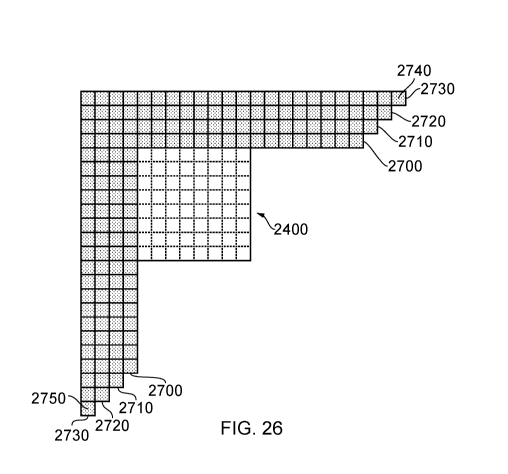
Various options will now be discussed relating to the number of rows and
columns of
reference samples. Again, as before, the examples are discussed with relation
to an 8x8 block
2400 of samples to be predicted, but the same techniques are applicable to
other sizes and/or
shapes of blocks.
Note however that in some examples, certain block sizes and/or shapes may be
excluded or restricted in their application of the present techniques, for
example small blocks,
such as blocks having either dimension equal to four samples or fewer.
Also, in the operation of an intra mode selector as discussed below, certain
directional
modes may be excluded from the present techniques.
Therefore, Figures 21 and 22 provide examples in which the intra-image
predictor is
configured to derive the predicted samples by interpolating amongst one or
more sets of
reference samples. For example, the intra-image predictor can be configured to
interpolate
amongst two or more sets of reference samples (such as (a, c, e) and (b, d, f)
in Figure 21, or
(c, e, g) and (b, d, f) in Figure 22) to derive a respective intermediate
sample value p1, p2 from
each set of reference samples, and to combine the intermediate sample values
to derive the
predicted sample p. In example arrangements set of reference samples comprises
samples
from a respective one or the two or more parallel arrays 2070, 2075 of
reference samples. In
the example of Figure 22, based around the reference positions 2090, 2095,
each set of
reference samples comprises a set, in the respective array of reference
samples, pointed to by
the prediction direction. As discussed above, the intra-image predictor 530
can be configured
to combine the intermediate sample values according to a weighted combination,
in which a
23
CA 03080084 2020-04-23
WO 2019/081927
PCT/GB2018/053077
weighting applied to an intermediate sample value decreases with increasing
separation of the
set of reference samples, from which that intermediate sample value as
generated, from the
current region (so that in the example given above, a weighting of 0.6 is
applied to the closer
array 2070 and a weighting of 0.4 is applied to the further array 2075) or the
current sample to
be predicted.
Figure 23 schematically illustrates a single row/column 2410 of reference
samples. If
this was the only option available to the intra predictor, the operation would
correspond to a
previously proposed intra predictor, but the use of a single row/column 2410
could be provided
in an intra predictor forming an embodiment of the present disclosure in the
context of its
optional selection (by the intra mode selector) in combination with the
optional selection (by the
intra mode selector) of one or more other techniques shown in Figures 24 to
26.
Figure 24 shows a pair of rows/columns 2500, 2510 in which, as discussed
above, the
row/column 2510 is extended by one or more samples 2520, 2530 so as to allow
for the use of
the full range of prediction directions discussed above.
Similarly, Figure 25 schematically represents three rows/columns of reference
samples
2600, 2610, 2620. The row/column 2620 is extended by one or more samples 2630,
2640 with
respect to the second row/column 2610, for the same reasons.
Finally as an example, although not representing a limit on the number of
rows/columns
which can be used, Figure 23 schematically illustrates four rows/columns of
reference samples,
mainly rows/columns 2700, 2710, 2720, 2730. Once again, the row/column 2730 is
extended by
one or more reference samples 2740, 2750 with respect to the third row/column
2720, for the
same reasons as those discussed above.
Figures 27-30 show, for the example cases of Figures 23-26 respectively, a
projected
version of the multiple rows/columns of reference samples (shown as shaded
blocks in Figures
.. 27-30). Note that in at least some examples, the projection process can be
dependent upon the
prediction direction in use, so a single example for an arbitrary prediction
direction is employed
in Figures 27-30. With respect to the projected reference sample, a similar
technique employed
to that in Figure 17 can be used to derive reference positions and reference
samples to apply
the technique of Figure 19.
Figure 31 schematically represents at least part of an operation of an intra
mode
selector such as the intra mode selector 520 of Figure 8 described above.
The intra mode selector can operate to detect an appropriate mode for use in
intra
prediction of a current block or region with respect to a set of reference
samples 3205. Various
techniques have been proposed for achieving this, such as (at least partial)
trial encoding
and/or analysis of properties of the reference samples, to select the
prediction operation
amongst the candidate prediction operations.
24
CA 03080084 2020-04-23
WO 2019/081927
PCT/GB2018/053077
In the present examples, any of these techniques can be used, with (in some
example
arrangements) the techniques being repeated, or applied in multiple instances,
in respect of
multiple permutations of the number of rows/columns of reference samples.
Here, the term "permutation" is used to indicate a group of rows/columns of
reference
samples. The group might include a row/column spatially nearest to the current
block or region,
and zero or more next-adjacent rows/columns each progressively spatially
further away from
the current block or region.
The term "prediction operation" can be used to describe a mode or direction
and/or an
associated permutation of rows/columns. Therefore, the intra-mode selector
can, in example
embodiments, be configured to select, from a set of candidate prediction
operations each
defining at least a prediction direction, a prediction operation for
prediction of samples of a
current region of a current image, the current region comprising an array of
two or more rows
and two or more columns of samples. The intra-image predictor is configured to
derive
predicted samples of the current region with respect to one or more of a group
of reference
samples of the same image in dependence upon a prediction direction, defined
by the selected
prediction operation, between a current sample to be predicted and a reference
position
amongst the reference samples. For at least some of the candidate prediction
operations, the
group of reference samples comprises two or more parallel linear arrays (such
as rows,
columns, rows and columns (noting that a row and column are still a linear
array even with a
"corner"), and/or projected arrays) of reference samples disposed at different
respective
separations from the current region.
The intra mode selector comprises a mode properties detector 3200 which acts
to detect
the encoding properties of each mode under test (and, in at least some
examples, of each
mode with each permutation Pn of numbers n of rows/columns of reference
samples available
with that mode, where n ranges from 1 to a maximum limit of at least two). A
coding efficiency
detector 3210 detects the coding efficiency for each mode/permutation tested
by the mode
properties detector 3200. The coding efficiency can relate to aspects such as
the amount of
data needed to encode the residual image which would arise where that mode and
permutation
of rows/columns to be used, along with the amount of data needed to signal the
use of that
mode/permutation.
In the selection of a prediction direction, example arrangements test all 34
directional
modes with a simple SAD (sum of absolute differences) test to derive a
shortlist of modes most
likely to be useful for the current block. The shortlist of modes is then
tested with a full encode
to select a prediction mode for use.
The current techniques using multiple rows and/or columns of reference samples
may in
some situations be slower (or have higher processing requirements) than using
a single
row/column. To alleviate this at the encoder side where such a decision is
made and then
CA 03080084 2020-04-23
WO 2019/081927
PCT/GB2018/053077
communicated to the decoder, example arrangements may be arranged to use the
multi
row/column prediction only for testing the shortlist of modes.
Based on the detection by the coding efficiency detector 3210, a mode selector
3220
selects a prediction mode 3230 to be sent to the intra predictor 530, and
information 3240 is
also sent to a mode encoder 3245 such as a part of the controller 343 which
encodes data 3250
forming part of the encoded data stream indicating the mode/permutation in
use, which is to
say, data identifying the prediction operation selected for each region of the
image.
Therefore, this provides an example in which the intra mode selector is
configured to
select amongst two or more groups of reference samples, each group comprising
a respective
different number of parallel arrays of reference samples.
Figures 32 and 33 are respective schematic flow charts representing possible
methods
of operation of the intra mode selector of Figure 31.
In Figure 32, steps 3300...3310, carried out in as many instances (whether in
series, as
schematically illustrated here, or in parallel) as there are available
permutations P of
rows/columns of reference samples, relate to the mode properties detector 3200
and coding
efficiency detector 3210 detecting a best mode using each possible permutation
of
rows/columns of reference samples. So, a best mode may be selected using a
single
row/column of reference samples, another best mode may be selected using two
rows/columns
of reference samples and so on. Then, at a step 3320, the coding efficiency
detector 3210
detects the efficiencies of each of the modes and permutations detected at the
step
3300...3310 so that at a step 3330 the mode selector 3220 selects a single
mode and
permutation of rows/columns and the mode encoder 3245 encodes information
defining the
selected mode and permutation.
In an alternative mode of operation in Figure 33, an initial stage during the
encoding
process is to establish use of a particular permutation of n rows/columns
(where n is at least
two, so the permutation might be two rows/columns) and communicate this to the
decoder in,
for example, a parameter set, at a step 3400. Then, at a step 3410, the mode
properties
detector 3200, the coding efficiency detector 3210 and the mode selector 3220
cooperate to
select a best prediction mode using the particular established permutation of
rows/columns and
at a step 3420 the mode encoder 3425 encodes information defining that mode.
At the decoder side, an intra mode selector is shown by way of example in
Figure 34,
comprising an encoded data detector 3500 which detects data such as the data
3250 in the
encoded data stream defining a particular mode (and optionally a set of
rows/columns) to be
used, and a mode selector 3510 provides information 3520 to the intra
predictor 530 indicating
which mode and permutation of rows/columns to use, that is to say, it is
configured to detect
encoded data identifying the prediction operation selected for each region of
the image.
26
CA 03080084 2020-04-23
WO 2019/081927
PCT/GB2018/053077
Figures 35 and 36 are respective flow charts schematically representing
methods of
operation of an intra predictor such as the intra predictor 530 of Figure 8.
Figure 35 relates primarily to the operations shown in Figures 21 and 22
above, in
which, at a step 3600, an intermediate predicted sample value such as the
intermediate
predicted sample value p2 is interpolated from a first set of reference
samples, for example the
set in a closest row/column of reference samples to the current block or
region, and then, using
as many iterations as there are rows/columns of reference samples, a step 3610
represents the
interpolation of an intermediate predicted sample value p1 from each remaining
set of reference
samples from a respective row/column of reference samples. As discussed above,
for those
rows/columns of reference samples further away from the current block or
region than the
closest row/column of reference sample, the selection of which reference
samples to use could
be, for example, by detecting a reference position in each row/column
according to the
prediction direction or by using corresponding locations to those identified
in the closest
row/column. Then, at a step 3620, the intermediate predicted sample values are
combined, for
example by a weighted mean, to generate the final predicted sample value.
Figure 36 relates more to the process shown in Figure 20, in which at a step
3700,
respective members of the two or more sets of reference samples (with sets
other than the set
in the closest row/column being defined for example by tracking a further
reference position
along the prediction direction) into a combined set (h, i, j of Figure 20),
and then interpolating a
predicted sample value p from the combined set a step 3710.
As an optional feature of the operation of the intra predictor, Figure 37
schematically
illustrates a technique for providing the additional reference samples 2520,
2530, 2630, 2640,
2740, 2750, or at least some of them, without necessarily having to simply
repeat nearby or
adjacent reference samples.
Referring to Figure 37, a missing reference sample detector 3800 detects that
a
reference sample is not available. This could be because a sample at that
position has not yet
necessarily been decoded. In some examples, the sample has not been decoded.
In other
examples, a sample could have been decoded, but because it lies outside a
current coding unit
it could be that the hardware requirements such as buffering needed to make
that reference
sample available for the current prediction would be unreasonably high and so
a design
decision is taken such that the sample is not provided for prediction. For
example, referring to
Figures 25 and 26, these considerations may indicate that the samples 2530,
2640, 2642 are
not available if they are outside the current coding unit. To address these
issues, in example
arrangements an extrapolator 3810 generates the required value 3820 using an
extrapolation
process based on multiple ones of the available reference samples. Operation
of this
arrangement is shown by schematic flowchart of Figure 38 in which a step 3900
relates to the
27
CA 03080084 2020-04-23
WO 2019/081927
PCT/GB2018/053077
detection by the detector 3800 of the missing reference samples and a step
3910 relates to the
extrapolation by the extrapolator 3810 of the required values.
Further examples illustrating the use of missing reference sample detection
will be
discussed below.
Figure 39 is a schematic flowchart illustrating an image encoding method
comprising:
selecting (at a step 4000), from a set of candidate prediction operations each
defining at
least a prediction direction, a prediction operation for prediction of samples
of a current region
of a current image, the current region comprising an array of two or more rows
and two or more
columns of samples; and
deriving (at a step 4010) intra-image predicted samples of the current region
with
respect to one or more of a group of reference samples of the same image in
dependence upon
a prediction direction, defined by the selected prediction operation, between
a current sample to
be predicted and a reference position amongst the reference samples;
in which, for at least some of the candidate prediction operations, the group
of reference
samples comprises two or more parallel linear arrays of reference samples
disposed at different
respective separations from the current region.
Figure 40 is a schematic flowchart illustrating an image encoding method
comprising:
selecting (at a step 4100), from a set of candidate prediction operations each
defining at
least a prediction direction, a prediction operation for prediction of samples
of a current region
of a current image, the current region comprising an array of two or more rows
and two or more
columns of samples; and
deriving (at a step 4110) intra-image predicted samples of the current region
with
respect to one or more of a group of reference samples of the same image in
dependence upon
a prediction direction, defined by the selected prediction operation, between
a current sample to
be predicted and a reference position amongst the reference samples;
in which, for at least some of the candidate prediction operations, the group
of reference
samples comprises two or more parallel linear arrays of reference samples
disposed at different
respective separations from the current region.
In at least some of the example arrangements discussed above, the use of
multiple rows
or columns of reference samples may be constrained to instances where the
"extra" (non-
adjacent) rows or the multiple columns (or both) lie in the same coding tree
unit as the current
block. These conditions can be applied individually or together. Such
arrangements will now
be described further.
Figure 41 schematically illustrates an array of coding units, in an example
arrangement
in which the image encoding apparatus is configured to encode the current
image as
successive coding units 4100 of samples.
28
CA 03080084 2020-04-23
WO 2019/081927
PCT/GB2018/053077
It will be appreciated from the discussion of Figure 9 above that in at least
some
embodiments, coding takes place, coding unit by coding unit, from top left to
bottom right of the
set of coding units 4100. This means that for image regions at the extreme
edges (the top edge
and/or the left edge in this example) of a coding unit, it may be the case
that at least some
-- samples which would be required as reference samples in plural linear
arrays as discussed
above may or may not be available, depending on how much (if any) of a
preceding decoded
coding unit has been buffered. For example, for a particular coding unit 4110,
prediction at the
top 4120 and/or the left 4130 of the coding unit may be affected in this way.
For coding units at
the left and/or top of the image, the required reference sample data may not
exist at all.
Note that the top left to bottom right encoding order is merely an example. If
another
order were used, the edges being considered here may be different to the top
and left edges
currently under discussion. Note also that the shape of the coding units shown
in the schematic
diagram of Figure 41 may or may not be representative of the actual shape or
relative sizes of
the coding units.
Figure 42 schematically illustrates a sample predictor 530', similar to the
intra-image
predictor 530 of Figure 8 but explicitly showing a sample store 4200 to store
samples
corresponding to a region of the current image other than the current region.
In particular, the
sample store 4200 can be arranged to store previously encoded and decoded
samples from
one or more coding units adjacent to the coding unit in which the current
region is located, for
use as reference samples in respect of (for example) an image region at a
location within the
current coding unit adjacent to a previous coding unit.
Figures 43 and 44 schematically illustrate reference sample storage by the
sample store
4200. In some examples, such as that shown schematically in Figure 43, the
sample store
4200 may be configured as a line store to store one or more lines or rows of
previously encoded
-- and decoded samples from a coding unit directly above a current coding unit
4310.
Here, it is noted that line stores are considered to be relatively
"expensive", the term
implying that they can require a significant amount of memory storage for
their implementation,
which can in turn require a significant amount of logic circuitry in, for
example, an integrated
circuit implementation of an encoder and/or decoder. The provision of line
stores therefore
represents a compromise between the potentially heavy requirements in terms of
logic circuitry
and the potential improvements in coding efficiency provided by the present
techniques in which
multiple rows and/or columns of reference samples may be used. Such reference
samples may
be readily available within a particular coding unit, but access to reference
samples from
outside the current coding unit can potentially be restricted by the
implementation (or lack of
implementation) of sample storage such as the sample store 4200.
29
CA 03080084 2020-04-23
WO 2019/081927
PCT/GB2018/053077
In Figure 44, a column of samples 4400 from a previously encoded and decoded
coding
unit to the left of the current coding unit 4410 is stored for use as
reference samples in respect
of a left hand column of regions of the coding unit 4410.
It will be appreciated that the sample store 4200 could store samples above
(as in
Figure 43) and to the left of (as in Figure 44) the current coding unit. It
will be appreciated that
one or more rows (and/or columns) of samples could be stored. It will be
appreciated that a
sample store 4200 may not in fact be provided.
Figure 45 schematically represents an intra mode selector arrangement of the
type
shown in Figure 31, except that the mode selector 3220' (similar in most
respects to the mode
selector 3220) is responsive to a detector 4500 configured to detect whether
samples
corresponding to any of the two or more parallel linear arrays of reference
samples are
unavailable for use in prediction of samples of the current region and, if any
of the two or more
parallel linear arrays of reference samples are unavailable, to inhibit
selection, by the intra
mode selector 3220', of a candidate prediction operation dependent upon the
unavailable
reference samples.
Note that this can be a separate test and mechanism to the arrangement of
Figure 38.
In the present test, it is detected whether any of the two or more parallel
linear arrays of
reference samples are unavailable for example, because the current region is
at a peripheral
position with respect to a coding unit and/or image, and/or because any of the
two or more
parallel linear arrays of reference samples are not buffered (for example in
line stores). A
sample-by-sample extrapolation process of the type used in Figure 38 is not
applied, but
instead, candidate prediction modes which use the unavailable rows/columns are
inhibited from
being selected.
Similarly, the detector 4500 is further configured to detect for a current
region of a
current image which, if any, of the two or more parallel linear arrays are
available for use in
prediction of samples of the current region and to allow selection as a
prediction operation, by
the selector, of a candidate prediction operation dependent upon at least one
of the available
parallel linear arrays. Therefore in example embodiments the detector 4500
allows or disallows
the selection of modes by the selector 3220' in dependence upon whether, for
the current
image region, the required rows and/or columns of reference samples are
available (for
example, stored or buffered).
The detector 4500 is in turn responsive to configuration data 4510 defining
the presence
or absence of the sample store 4200 and in particular defining how many (if
any) rows and/or
columns of samples of a previous adjacent coding unit it holds for use as
reference samples in
respect of image regions of the current coding unit.
Significantly, the configuration data 4510 may define the lower of: (a) which
stores are
present at the decoder side and (b) which stores are available or present at
the encoder side.
CA 03080084 2020-04-23
WO 2019/081927
PCT/GB2018/053077
This is because the selected mode will ultimately need to be implemented at
the decoder, but
the mode cannot be implemented in encoding unless the relevant stores are also
present at the
encoder side. If the encoded data is to be ultimately decoded by a known
decoder, the
properties of that decoder can be provided as the configuration data 4510. If
however the
decoder is unknown, then it may be that the configuration data 4510 defines
zero sample stores
(even if one or more are present at the encoder) so as not to allow the
generation of encoded
data that cannot be decoded by an arbitrary decoder. In other examples, if a
decoder standard,
whether an official standard, a proprietary standard or a de facto industry
standard, specifies
that (for example) one line store (or a generic number n of line stores) must
always be present,
then for an unknown decoder the configuration data 4510 can be arranged to
specify n line
stores, assuming that n line stores are available at the encoder.
In this way, the detector 4500 can be responsive to configuration data
defining one or
more parameters of a decoding apparatus to detect whether samples
corresponding to any of
the two or more parallel linear arrays of reference samples will be available
for use in prediction
of samples of the current region at the decoding apparatus.
The detector 4500 is also responsive to location information 4520 defining the
image
location of the current image region with respect to the image and/or the
current coding unit. If
the current image region is adjacent a left or upper edge of the image then
the detector can be
configured to detect that multiple rows and/or columns of reference samples
are unavailable. If
the current image region is adjacent a left and/or upper edge of a coding
unit, then the detector
can be configured to detect that multiple rows and/or columns of reference
samples are
unavailable unless the configuration data 4510 defines that such samples are
held by sample
stores 4200. Therefore, in these examples, the detector is configured to
detect whether, for an
image region at a location within a coding unit adjacent to a previous coding
unit, any of the two
.. or more parallel linear arrays of reference samples are held by the sample
store.
Figures 46 to 49 are schematic diagrams illustrating prediction processes,
showing
example operations of the detector 4500 to detect whether the current region
is adjacent an
edge of the current region such that sample locations corresponding to at
least some of the two
or more parallel linear arrays of reference samples lie outside the current
image.
In Figures 46 and 47, an image region 4600 being encoded or decoded is at the
top of
its respective coding unit. The boundary with the next-above coding unit is
schematically
represented by a bold line 4610. In this example instance a sample store 4200
providing one
line store is used, so that one line of samples from the next-above coding
unit is available for
use as reference samples. A second row of reference samples is not available
above the
image region 4600.
In Figure 46, a single row of reference samples is used for predictions
involving a
reference position amongst the reference samples above the image region 4600,
such as a
31
CA 03080084 2020-04-23
WO 2019/081927
PCT/GB2018/053077
reference position 4620. However, because (in the example of Figure 46) two or
more columns
of samples 4630 are available to the left of the region 4600 for use as
reference samples,
predictions involving a reference position amongst the reference samples to
the left of the
image region 4600, such as a prediction represented by an arrow 4640, use two
columns or
linear arrays of reference samples.
In Figure 47, only a single linear array (row, column) is used for prediction
for all
reference sample locations so that a consistent technique is used in respect
of all of the
predictions. This is done even because the second row above is not available;
even though the
second column 4700 is available it is unused.
In Figures 48 and 49, once again the current image region 4800 is at the top
of a coding
unit (with the boundary 4810 being shown by a bold line).
In Figure 48, one line store is
available, and in Figure 49 two line stores are available.
In Figure 48, single row prediction is used for reference sample positions
above the
current image region 4800 such as a reference sample position 4820, but for
reference sample
positions to the left, four column 4830 prediction (using any of the
techniques described above)
can d be used. This applies to reference sample locations which do not use row
data but only
column data.
In Figure 49, an extra line store is used (or in other words, two line stores
are provided)
so a double row/column prediction is used for all sample locations. Although a
third and fourth
column 4900 are available they are unused, so as to provide a consistent
approach, although
other examples could use two rows for reference sample positions above the
current region and
four columns for reference sample positions to the left of the current region.
Note that in all of the embodiments described here, for multiple rows/columns
the
prediction may be a weighted sum but this might be for example a 0:100:0:0
weighting rather
than necessarily a 25:25:25:25 weighting (where the four weightings are in
order of array
separation from the current image region, for example, the first, second,
third and fourth
adjacent rows/columns). This could be implemented as a multiplexer.
Accordingly, in at least Figures 46 and 48 the detector 4500 is configured to
detect,
separately for reference sample positions disposed vertically or horizontally
with respect to the
.. current image region, whether samples corresponding to any of the two or
more parallel linear
arrays of reference samples are unavailable for use in prediction of samples
of the current
region (being, for example, all candidate prediction modes except those which
rely on line
stores or sample provision which are not present in respect of the current
region) and, if any of
the two or more parallel linear arrays of reference samples are unavailable
for reference sample
positions disposed vertically or horizontally with respect to the current
image region, to inhibit
selection, by the selector, of a candidate prediction operation dependent upon
the unavailable
reference samples. Note that the detection can take place region by region,
since the presence
32
CA 03080084 2020-04-23
WO 2019/081927
PCT/GB2018/053077
or absence of line stores is generally relevant only to the top row of regions
and/or to modes
which rely on samples above the current region.
In the situation such as at the top of the image (as shown by 4140 in Figure
41),
regardless of what local buffering is present, samples above a current region
may not be
available simply because the current region is at the very top of the image.
In such
circumstances predetermined value (for example grey) samples can be
substituted for the
reference samples. The detector 4500 can detect this situation from the
location information
4520 and control the detector 4500 so as to disallow use of modes other than
those which rely
on the predetermined reference samples. Therefore in example embodiments, for
at least
some of the candidate prediction operations, the group of reference samples
comprises one or
more predetermined values; and the detector 4500 is further configured to
detect for a current
region of a current image if none of the two or more parallel linear arrays is
available for use in
prediction of samples of the current region and to allow selection as a
prediction operation, by
the selector, of a candidate prediction operation for that current region
dependent upon the
predetermined values as reference samples.
At the decoder side, corresponding detections, derivations and control
operations by the
detector could be carried out, or alternatively the nature of the encoding
could be
communicated to the decoder in the same way as that described with reference
to Figure 34
described above.
Figures 50 and 51 are schematic flowcharts illustrating respective methods.
Figure 50 is a schematic flowchart illustrating an image encoding method
comprising:
selecting (at a step 5000), from a set of candidate prediction operations each
defining at
least a prediction direction, a prediction operation for prediction of samples
of a current region
of a current image, the current region comprising an array of two or more rows
and two or more
columns of samples;
deriving (at a step 5010) intra-image predicted samples of the current region
with
respect to one or more of a group of reference samples of the same image in
dependence upon
a prediction direction, defined by the selected prediction operation, between
a current sample to
be predicted and a reference position amongst the reference samples;
in which, for at least some of the candidate prediction operations, the group
of reference
samples comprises two or more parallel linear arrays of reference samples
disposed at different
respective separations from the current region;
detecting (at a step 5020) whether samples corresponding to any of the two or
more
parallel linear arrays of reference samples are unavailable for use in
prediction of samples of
the current region and
33
CA 03080084 2020-04-23
WO 2019/081927
PCT/GB2018/053077
inhibiting (at a step 5030) selection by the selecting step, if any of the two
or more
parallel linear arrays of reference samples are unavailable, of a candidate
prediction operation
dependent upon the unavailable reference samples.
Figure 51 is a schematic flowchart illustrating an image decoding method
comprising:
selecting (at a step 5100), from a set of candidate prediction operations each
defining at
least a prediction direction, a prediction operation for prediction of samples
of a current region
of a current image, the current region comprising an array of two or more rows
and two or more
columns of samples;
deriving (at a step 5110) intra-image predicted samples of the current region
with
respect to one or more of a group of reference samples of the same image in
dependence upon
a prediction direction, defined by the selected prediction operation, between
a current sample to
be predicted and a reference position amongst the reference samples;
in which, for at least some of the candidate prediction operations, the group
of reference
samples comprises two or more parallel linear arrays of reference samples
disposed at different
respective separations from the current region;
detecting (at a step 5120) whether samples corresponding to any of the two or
more
parallel linear arrays of reference samples are unavailable for use in
prediction of samples of
the current region and
inhibiting (at a step 5130) selection by the selecting step, if any of the two
or more
parallel linear arrays of reference samples are unavailable, of a candidate
prediction operation
dependent upon the unavailable reference samples.
In so far as embodiments of the disclosure have been described as being
implemented,
at least in part, by software-controlled data processing apparatus, it will be
appreciated that a
non-transitory machine-readable medium carrying such software, such as an
optical disk, a
magnetic disk, semiconductor memory or the like, is also considered to
represent an
embodiment of the present disclosure. Similarly, a data signal comprising
coded data
generated according to the methods discussed above (whether or not embodied on
a non-
transitory machine-readable medium) is also considered to represent an
embodiment of the
present disclosure.
It will be apparent that numerous modifications and variations of the present
disclosure
are possible in light of the above teachings. It is therefore to be understood
that within the
scope of the appended clauses, the technology may be practised otherwise than
as specifically
described herein.
Respective aspects and features are defined by the following numbered clauses:
1. An image encoding apparatus comprising:
a selector configured to select, from a set of candidate prediction operations
each
defining at least a prediction direction, a prediction operation for
prediction of samples of a
34
CA 03080084 2020-04-23
WO 2019/081927
PCT/GB2018/053077
current region of a current image, the current region comprising an array of
two or more rows
and two or more columns of samples; and
an intra-image predictor configured to derive predicted samples of the current
region
with respect to one or more of a group of reference samples of the same image
in dependence
upon a prediction direction, defined by the selected prediction operation,
between a current
sample to be predicted and a reference position amongst the reference samples;
in which, for at least some of the candidate prediction operations, the group
of reference
samples comprises two or more parallel linear arrays of reference samples
disposed at different
respective separations from the current region.
2. Apparatus according to clause 1, in which the intra-image predictor is
configured to
derive the predicted samples by interpolating amongst one or more sets of
reference samples.
3. Apparatus according to clause 2, in which the intra-image predictor is
configured to
interpolate amongst two or more sets of reference samples to derive a
respective intermediate
sample value from each set of reference samples, and to combine the
intermediate sample
values to derive the predicted sample.
4. Apparatus according to clause 3, in which each set of reference samples
comprises
samples from a respective one or the two or more parallel arrays of reference
samples.
5. Apparatus according to clause 4, in which each set of reference samples
comprises a
set, in the respective array of reference samples, or of values interpolated
from the respective
array of reference samples, pointed to by the prediction direction.
6. Apparatus according to clause 3 or clause 4, in which the intra-image
predictor is
configured to combine the intermediate sample values according to a weighted
combination, in
which a weighting applied to an intermediate sample value decreases with
increasing
separation of the set of reference samples, from which that intermediate
sample value as
generated, from the current region.
7. Apparatus according to clause 3, in which the intra-image predictor is
configured to
combine the intermediate sample values according to a weighted combination, in
which a
weighting applied to an intermediate sample value derived from reference
samples non-
adjacent to the current image region increases with increasing separation of
the set of reference
samples, from which that intermediate sample value as generated, from the
current sample to
be predicted.
8. Apparatus according to any one of the preceding clauses, in which the
intra-image
predictor is configured to combine two or more sets of reference samples to
derive intermediate
reference sample values, and to derive the predicted sample from the
intermediate reference
sample values.
9. Apparatus according to clause 8, in which the intra-image predictor is
configured to
derive the predicted samples by interpolating amongst the intermediate
reference samples.
CA 03080084 2020-04-23
WO 2019/081927
PCT/GB2018/053077
10. Apparatus according to clause 8 or clause 9, in which each set of
reference samples
comprises samples from a respective one or the two or more parallel arrays of
reference
samples.
11. Apparatus according to clause 10, in which each set of reference
samples comprises a
set, in the respective array of reference samples, pointed to by the
prediction direction.
12. Apparatus according to clause 8, in which the intra-image predictor is
configured to
combine the reference sample values according to a weighted combination, in
which a
weighting applied to a reference sample value decreases with increasing
separation of the set
of reference samples containing that reference sample value, from the current
region.
13. Apparatus according to clause 8, in which the intra-image predictor is
configured to
combine the reference sample values according to a weighted combination, in
which a
weighting applied to a reference sample value non-adjacent to the current
image region
increases with increasing separation of the set of reference samples
containing that reference
sample value, from the current sample to be predicted.
14. Apparatus according to clause 8, in which the intra-image predictor is
configured to
combine the two or more parallel linear arrays of reference samples to form a
linear array of
reference samples.
15. Apparatus according to any one of the preceding clauses, in which the
selector is
configured to select amongst two or more groups of reference samples, each
group comprising
a respective different number of parallel arrays of reference samples.
16. Apparatus according to any one of the preceding clauses, in which the
selector is
configured to perform at least a partial encoding to select the prediction
operation amongst the
candidate prediction operations.
17. Apparatus according to any one of the preceding clauses, in which the
controller is
configured to encode data identifying the prediction operation selected for
each region of the
image.
18. Video storage, capture, transmission or reception apparatus comprising
apparatus
according to any one of the preceding clauses.
19. An image decoding apparatus comprising:
a selector configured to select, from a set of candidate prediction operations
each
defining at least a prediction direction, a prediction operation for
prediction of samples of a
current region of a current image, the current region comprising an array of
two or more rows
and two or more columns of samples; and
an intra-image predictor configured to derive predicted samples of the current
region
with respect to one or more of a group of reference samples of the same image
in dependence
upon a prediction direction, defined by the selected prediction operation,
between a current
sample to be predicted and a reference position amongst the reference samples;
36
CA 03080084 2020-04-23
WO 2019/081927
PCT/GB2018/053077
in which, for at least some of the candidate prediction operations, the group
of reference
samples comprises two or more parallel linear arrays of reference samples
disposed at different
respective separations from the current region.
20. Apparatus according to clause 19, in which the intra-image predictor is
configured to
derive the predicted samples by interpolating amongst one or more sets of
reference samples.
21. Apparatus according to clause 20, in which the intra-image predictor is
configured to
interpolate amongst two or more sets of reference samples to derive a
respective intermediate
sample value from each set of reference samples, and to combine the
intermediate sample
values to derive the predicted sample.
22. Apparatus according to clause 21, in which each set of reference
samples comprises
samples from a respective one or the two or more parallel arrays of reference
samples.
23. Apparatus according to clause 22, in which each set of reference
samples comprises a
set, in the respective array of reference samples, pointed to by the
prediction direction.
24. Apparatus according to clause 21, in which the intra-image predictor is
configured to
.. combine the intermediate sample values according to a weighted combination,
in which a
weighting applied to an intermediate sample value decreases with increasing
separation of the
set of reference samples, from which that intermediate sample value as
generated, from the
current region.
25. Apparatus according to clause 19, in which the intra-image predictor is
configured to
.. combine two or more sets of reference samples to derive intermediate
reference sample values,
and to derive the predicted sample from the intermediate reference sample
values.
26. Apparatus according to clause 25, in which the intra-image predictor is
configured to
derive the predicted samples by interpolating amongst the intermediate
reference samples.
27. Apparatus according to clause 25, in which each set of reference
samples comprises
samples from a respective one or the two or more parallel arrays of reference
samples.
28. Apparatus according to clause 27, in which each set of reference
samples comprises a
set, in the respective array of reference samples, pointed to by the
prediction direction.
29. Apparatus according to clause 25, in which the intra-image predictor is
configured to
combine the reference sample values according to a weighted combination, in
which a
weighting applied to a reference sample value decreases with increasing
separation of the set
of reference samples containing that reference sample value, from the current
region.
30. Apparatus according to clause 25, in which the intra-image predictor is
configured to
combine the two or more parallel linear arrays of reference samples to form a
linear array of
reference samples.
31. Apparatus according to any one of clauses 19 to 30, in which the
selector is configured
to select amongst two or more groups of reference samples, each group
comprising a
respective different number of parallel arrays of reference samples.
37
CA 03080084 2020-04-23
WO 2019/081927
PCT/GB2018/053077
32. Apparatus according to any one of clauses 19 to 31, in which the
controller is configured
to detect encoded data identifying the prediction operation selected for each
region of the
image.
33. Video storage, capture, transmission or reception apparatus comprising
apparatus
according to any one of clauses 19 to 32.
34. An image encoding method comprising:
selecting, from a set of candidate prediction operations each defining at
least a
prediction direction, a prediction operation for prediction of samples of a
current region of a
current image, the current region comprising an array of two or more rows and
two or more
columns of samples; and
deriving intra-image predicted samples of the current region with respect to
one or more
of a group of reference samples of the same image in dependence upon a
prediction direction,
defined by the selected prediction operation, between a current sample to be
predicted and a
reference position amongst the reference samples;
in which, for at least some of the candidate prediction operations, the group
of reference
samples comprises two or more parallel linear arrays of reference samples
disposed at different
respective separations from the current region.
35. Computer software which, when executed by a computer, causes the
computer to carry
out a method according to clause 34.
36. A machine-readable non-transitory storage medium which stores software
according to
clause 35.
37. A data signal comprising coded data generated according to the method
of clause 34.
38. An image decoding method comprising:
selecting, from a set of candidate prediction operations each defining at
least a
prediction direction, a prediction operation for prediction of samples of a
current region of a
current image, the current region comprising an array of two or more rows and
two or more
columns of samples; and
deriving intra-image predicted samples of the current region with respect to
one or more
of a group of reference samples of the same image in dependence upon a
prediction direction,
defined by the selected prediction operation, between a current sample to be
predicted and a
reference position amongst the reference samples;
in which, for at least some of the candidate prediction operations, the group
of reference
samples comprises two or more parallel linear arrays of reference samples
disposed at different
respective separations from the current region.
39. Computer software which, when executed by a computer, causes the
computer to carry
out a method according to clause 38.
38
CA 03080084 2020-04-23
WO 2019/081927
PCT/GB2018/053077
40. A machine-readable non-transitory storage medium which stores software
according to
clause 39.
41. A video capture apparatus comprising an image sensor and the encoding
apparatus of
any one of clauses 1-17, decoding apparatus of any one of clauses 19-32 and a
display to
which the decoded images are output.
Further respective aspects and features are defined by the following numbered
clauses:
1. An image encoding apparatus comprising:
a selector configured to select, from a set of candidate prediction operations
each
defining at least a prediction direction, a prediction operation for
prediction of samples of a
current region of a current image, the current region comprising an array of
two or more rows
and two or more columns of samples;
an intra-image predictor configured to derive predicted samples of the current
region
with respect to one or more of a group of reference samples of the same image
in dependence
upon a prediction direction, defined by the selected prediction operation,
between a current
sample to be predicted and a reference position amongst the reference samples;
in which, for at least some of the candidate prediction operations, the group
of reference
samples comprises two or more parallel linear arrays of reference samples
disposed at different
respective separations from the current region; and
a detector configured to detect whether samples corresponding to any of the
two or
more parallel linear arrays of reference samples are unavailable for use in
prediction of samples
of the current region and, if any of the two or more parallel linear arrays of
reference samples
are unavailable, to inhibit selection, by the selector, of a candidate
prediction operation
dependent upon the unavailable reference samples.
2. Apparatus according to clause 1, in which the detector is further
configured to detect for
a current region of a current image which, if any, of the two or more parallel
linear arrays are
available for use in prediction of samples of the current region and to allow
selection as a
prediction operation, by the selector, of a candidate prediction operation
dependent upon at
least one of the available parallel linear arrays.
3. Apparatus according to clause 1 or clause 2, in which:
for at least some of the candidate prediction operations, the group of
reference samples
comprises one or more predetermined values;
the detector is further configured to detect for a current region of a current
image if none
of the two or more parallel linear arrays is available for use in prediction
of samples of the
current region and to allow selection as a prediction operation, by the
selector, of a candidate
prediction operation for that current region dependent upon the predetermined
values as
reference samples.
39
CA 03080084 2020-04-23
WO 2019/081927
PCT/GB2018/053077
4. Apparatus according to any one of the preceding clauses, in which the
detector is
responsive to an image location of the current region.
5. Apparatus according to clause 4, in which the detector is configured to
detect whether
the current region is adjacent an edge of the current region such that sample
locations
corresponding to at least some of the two or more parallel linear arrays of
reference samples lie
outside the current image.
6. Apparatus according to clause 4 or clause 5, in which:
the image encoding apparatus is configured to encode the current image as
successive
coding units of samples;
the image encoding apparatus comprises a sample store to store samples
corresponding to a region of the current image other than the current region;
and
the detector is configured to detect whether, for an image region at a
location within a
coding unit adjacent to a previous coding unit, any of the two or more
parallel linear arrays of
reference samples are held by the sample store.
7. Apparatus according to any one of the preceding clauses, in which the
detector is
configured to detect, separately for reference sample positions disposed
vertically or
horizontally with respect to the current image region, whether samples
corresponding to any of
the two or more parallel linear arrays of reference samples are unavailable
for use in prediction
of samples of the current region and, if any of the two or more parallel
linear arrays of reference
samples are unavailable for reference sample positions disposed vertically or
horizontally with
respect to the current image region, to inhibit selection, by the selector, of
a candidate
prediction operation dependent upon the unavailable reference samples.
8. Apparatus according to any one of the preceding clauses, in which the
detector is
responsive to configuration data defining one or more parameters of a decoding
apparatus to
detect whether samples corresponding to any of the two or more parallel linear
arrays of
reference samples will be available for use in prediction of samples of the
current region at the
decoding apparatus.
9. Video storage, capture, transmission or reception apparatus comprising
apparatus
according to any one of the preceding clauses.
10. An image decoding apparatus comprising:
a selector configured to select, from a set of candidate prediction operations
each
defining at least a prediction direction, a prediction operation for
prediction of samples of a
current region of a current image, the current region comprising an array of
two or more rows
and two or more columns of samples;
an intra-image predictor configured to derive predicted samples of the current
region
with respect to one or more of a group of reference samples of the same image
in dependence
CA 03080084 2020-04-23
WO 2019/081927
PCT/GB2018/053077
upon a prediction direction, defined by the selected prediction operation,
between a current
sample to be predicted and a reference position amongst the reference samples;
in which, for at least some of the candidate prediction operations, the group
of reference
samples comprises two or more parallel linear arrays of reference samples
disposed at different
respective separations from the current region; and
a detector configured to detect whether samples corresponding to any of the
two or
more parallel linear arrays of reference samples are unavailable for use in
prediction of samples
of the current region and, if any of the two or more parallel linear arrays of
reference samples
are unavailable, to inhibit selection, by the selector, of a candidate
prediction operation
dependent upon the unavailable reference samples.
11. Apparatus according to clause 10, in which the detector is further
configured to detect
for a current region of a current image which, if any, of the two or more
parallel linear arrays are
unavailable for use in prediction of samples of the current region and to
allow selection as a
prediction operation, by the selector, of a candidate prediction operation
dependent upon at
least one of the available parallel linear arrays.
12. Apparatus according to clause 10 or clause 11, in which:
for at least some of the candidate prediction operations, the group of
reference samples
comprises one or more predetermined values;
the detector is further configured to detect for a current region of a current
image if none
of the two or more parallel linear arrays is available for use in prediction
of samples of the
current region and to allow selection as a prediction operation, by the
selector, of a candidate
prediction operation for that current region dependent upon the predetermined
values as
reference samples.
13. Apparatus according to any one of clauses 10 to 12, in which the
detector is responsive
to an image location of the current region.
14. Apparatus according to clause 13, in which the detector is configured
to detect whether
the current region is adjacent an edge of the current region such that sample
locations
corresponding to at least some of the two or more parallel linear arrays of
reference samples lie
outside the current image.
15. Apparatus according to clause 13 or clause 14, in which:
the image decoding apparatus is configured to decode the current image as
successive
coding units of samples;
the image decoding apparatus comprises a sample store to store samples
corresponding to a region of the current image other than the current region;
and
the detector is configured to detect whether, for an image region at a
location within a
coding unit adjacent to a previous coding unit, any of the two or more
parallel linear arrays of
reference samples are held by the sample store.
41
CA 03080084 2020-04-23
WO 2019/081927
PCT/GB2018/053077
16. Apparatus according to any one of clauses 10 to 15, in which the
detector is configured
to detect, separately for reference sample positions disposed vertically or
horizontally with
respect to the current image region, whether samples corresponding to any of
the two or more
parallel linear arrays of reference samples are unavailable for use in
prediction of samples of
the current region and, if any of the two or more parallel linear arrays of
reference samples are
unavailable for reference sample positions disposed vertically or horizontally
with respect to the
current image region, to inhibit selection, by the selector, of a candidate
prediction operation
dependent upon the unavailable reference samples.
17. Video storage, capture, transmission or reception apparatus comprising
apparatus
according to any one of clauses 10 to 16.
18. An image encoding method comprising:
selecting, from a set of candidate prediction operations each defining at
least a
prediction direction, a prediction operation for prediction of samples of a
current region of a
current image, the current region comprising an array of two or more rows and
two or more
columns of samples;
deriving intra-image predicted samples of the current region with respect to
one or more
of a group of reference samples of the same image in dependence upon a
prediction direction,
defined by the selected prediction operation, between a current sample to be
predicted and a
reference position amongst the reference samples;
in which, for at least some of the candidate prediction operations, the group
of reference
samples comprises two or more parallel linear arrays of reference samples
disposed at different
respective separations from the current region;
detecting whether samples corresponding to any of the two or more parallel
linear arrays
of reference samples are unavailable for use in prediction of samples of the
current region and
inhibiting selection by the selecting step, if any of the two or more parallel
linear arrays
of reference samples are unavailable, of a candidate prediction operation
dependent upon the
unavailable reference samples.
19. Computer software which, when executed by a computer, causes the
computer to carry
out a method according to clause 18.
20. A machine-readable non-transitory storage medium which stores software
according to
clause 19.
21. A data signal comprising coded data generated according to the method
of clause 18.
22. An image decoding method comprising:
selecting, from a set of candidate prediction operations each defining at
least a
prediction direction, a prediction operation for prediction of samples of a
current region of a
current image, the current region comprising an array of two or more rows and
two or more
columns of samples;
42
CA 03080084 2020-04-23
WO 2019/081927
PCT/GB2018/053077
deriving intra-image predicted samples of the current region with respect to
one or more
of a group of reference samples of the same image in dependence upon a
prediction direction,
defined by the selected prediction operation, between a current sample to be
predicted and a
reference position amongst the reference samples;
in which, for at least some of the candidate prediction operations, the group
of reference
samples comprises two or more parallel linear arrays of reference samples
disposed at different
respective separations from the current region;
detecting whether samples corresponding to any of the two or more parallel
linear arrays
of reference samples are unavailable for use in prediction of samples of the
current region and
inhibiting selection by the selecting step, if any of the two or more parallel
linear arrays
of reference samples are unavailable, of a candidate prediction operation
dependent upon the
unavailable reference samples.
23. Computer software which, when executed by a computer, causes the
computer to carry
out a method according to clause 22.
24. A machine-readable non-transitory storage medium which stores software
according to
clause 23.
43