Note: Descriptions are shown in the official language in which they were submitted.
IN THE UNITED STATES PATENT AND TRADEMARK OFFICE
Alexandria, Virginia
NON-PROVISIONAL PATENT APPLICATION UNDER
37 C.F.R. 1.53(b)
for
MANAGING AND CONTROLLING ACCESS TO SECURED AREAS
RELATED APPLICATIONS
[0001] This application claimed the benefit of U.S. Provisional Application
No. 62/844,343,
filed May 7, 2019, the entire disclosures of which are incorporated herein by
this reference.
TECHNICAL FIELD
[0002] Exemplary embodiments of the present invention relate to access control
management for enclosed areas that are secured at access points to the
enclosed areas. More
specifically, exemplary embodiments relate to access control environments
utilize portable user
devices, entry control systems at the access points for controlling access to
the enclosed areas,
and remote access management systems for managing access privileges for the
enclosed areas.
BACKGROUND
[0003] Access control systems are commonly used to limit access to enclosed
areas such as
residential and commercial premises, fenced-in regions, and buildings to only
persons who have
been granted permission to enter. In such systems, physical access to the
enclosed area is secured
by placing a movable barrier that is moved between open and closed positions
by an electric
motor and controlled by installing an entry control system that operates to
generate control
-1-
CA 3080097 2020-05-07
signals for unlocking and/or moving the barrier to an open position, thereby
permitting access to
the secured area. Upon being unlocked or moved to an open position, the
barrier typically
remains open for a specified amount of time. Such a movable barrier may be a
gate, a door, or
the like, and may be constructed as an access point to a secured area within a
fence or a wall that
encloses the secured area.
[0004] In various conventional systems, the control signal for opening the
barrier and
thereby providing access to the enclosed area secured by the barrier may be
generated in
response to a coded input entered on a keypad adjacent the barrier by an
authorized person who
has been provided with the code, an input at the secured area or proximate to
the barrier by a
person wishing to provide access to a visitor at the barrier who has been
identified through a
communication system linking the barrier and the premises, or an access card
reader adjacent to
the barrier reading information from access control card that has been
provided to and is carried
by an authorized person and communicating the information read from the card
to a control unit
that determines that the barrier should be opened (that is, the card is
associated with a person
who has permission to enter).
[0005] In a more sophisticated implementation, such an access control system
can utilize a
wide area or cellular network connection with a remote management system for
performing
authentication of a person wishing to access a secured area to determine
whether access
credentials provided by the person to the entry control system indicate that
the person is
authorized, although such implementations typically require the entry control
system to be
continuously coupled to the remote management system over a secure
communication channel
via the network for validating access privileges for persons wishing to access
the secured area.
-2-
CA 3080097 2020-05-07
[0006] However, current systems typically require connectivity between an
access control
point and a central server that provides access information for authorized
users. In numerous
situations, connectivity may not be available or practical. As an example, for
remote
communities, such as camping or hunting lodges, cellular, wifi, or hardline
access may not be
present or economically feasible to install. In addition, even when such
access is possible, access
systems may require a physical power line to ensure that the cellular, wifi,
or hardline access
provides the connectivity to the central server system.
[0007] While physical locks are possible to use in such instances, such
systems may be less
secure, do not provide traceability with respect to logging of authorized
users who access a
secure area protected by an access control system, and physical locks cannot
provide the added
security associated with dynamic code generation. In addition, physical locks
are not convenient
if in a remote location if a temporary visitor or vendor requires access as a
physical key is
typically required which may be an inconvenient or less secure option.
[0008] Likewise, locks controlled by physical or electronic keypads lack the
ability to be
updated in remote areas with the intervention of a technician which can be
costly and
inconvenient, particularly if only required on temporary or sporadic basis
when a vendor or
temporary visitor needs access to a particular secured area.
[0009] The inventions described herein overcomes the disadvantages of the
above described
conventional technologies used to control access to secure areas.
SUMMARY
[0010] Exemplary embodiments of the present invention are related to methods
for
managing and controlling access to secured areas. Some exemplary
implementations of the
method comprise providing a first code to a client system via a network, the
first code being
-3-
CA 3080097 2020-05-07
stored in an application resident on the client system; capturing the first
code from the client
system when the client system is brought into proximity of an entry control
system via a local
connection to the entry control system; comparing the first code with a second
code, the second
code being a predetermined code previously provided to the entry control
system; and granting
access to a secured area if the first code and second code match.
[0011] Some exemplary implementations of the method further comprise providing
multiple
additional codes and each of the multiple additional codes are captured from
the client system
when the client system is brought into proximity of the entry control system.
In some
embodiments, the multiple additional codes are captured from the client system
if the first code
and second code match. In some embodiments, the first and second codes are
associated with a
first authorized user and one of the multiple additional codes is associated
with a second
authorized user.
[0012] In some embodiments, the entry control system is previously provided
with a list of
predetermined codes that correspond to the multiple additional codes.
[0013] In some embodiments, one of the multiple additional codes is a first
verification code
which is compared to a second verification code previously provided to the
entry control system.
Access is granted to the secured area if both (1) the first code and second
code match and (2) the
first verification code and the second verification code match. In some
embodiments, the first
and second codes are associated with one of multiple authorized users and the
first and second
verification codes are associated with one of multiple entry control systems.
[0014] In some embodiments, the first code, the second code, or both the first
code and the
second code include information about a predetermined time interval in which
to grant access to
-4-
CA 3080097 2020-05-07
=
A
the secured area and access is granted to the secured area if (1) the first
code and second code
match and (2) the first code is captured during the predetermined time
internal.
[0015] In some embodiments, the client system is additionally provided a
future access code
and the future access code is captured from the client system when the client
system is brought
into proximity of the entry control system. In such embodiment, the exemplary
implementation
of the method further comprises providing an access code to a second client
system via the
network, the access code being stored in an application resident on the second
client system;
capturing the access code from the second client system when the second client
system is
brought into proximity of the entry control system via the local connection to
the entry control
system; comparing the access code with the future access code previously
provided to the entry
control system; and granting access to the secured area if the access code and
future access code
match.
[0016] In some embodiments, the first code is a pseudorandom code generated on
the client
system and wherein the second code is a pseudorandom code generated on the
entry control
system.
[0017] In some embodiments, the second code is a hard wired to the entry
control system.
[0018] In some embodiments, the local connection provides for bidirectional
data flow
between the client system and the entry control system. In such embodiment,
some exemplary
implementations of the method further comprises capturing status information
about the entry
control system from the entry control system when the client system is brought
into proximity of
the entry control system via the local connection.
-5-
CA 3080097 2020-05-07
[0019] Some exemplary implementations of the method further comprise
establishing a
connection between the client system and a remote access management system via
the network,
the remote access management system providing the first code to the client
system.
[0020] Some exemplary implementations of the method further comprise capturing
status
information about the entry control system from the entry control system when
the client system
is brought into proximity of the entry control system via the local connection
and providing the
status information to the remote access management system.
[0021] Exemplary embodiments of the present invention are related to methods
for updating
a keypad code for an entry control system. Some exemplary implementations of
the method
comprise providing a first code to a client system via a network; capturing
the first code from the
client system when the client system is brought into proximity of an entry
control system via a
local connection to the entry control system; comparing the first code with a
second code, the
second code being a predetermined code previously provided to the entry
control system; and
updating a keypad code associated with an authorized user for a keypad
provided in
communication with the entry control system. When the keypad code is entered
on the keypad,
the entry control system grants access to a secured area.
[0022] In some embodiments, an application resident is provided on the client
system and
the first code is stored in the application.
[0023] Some exemplary implementations of the method further comprise verifying
the
keypad code based on a predetermined code stored on the entry control system
and updating the
keypad code if verified.
-6-
CA 3080097 2020-05-07
a
[0024] Exemplary embodiments of the present invention that are related to data
processing
systems and computer program products corresponding to the above-summarized
method are
also described and claimed herein.
[0025] The above-described and other features and advantages realized through
the
techniques of the present disclosure will be better appreciated and understood
with reference to
the following detailed description, drawings, and appended claims. Additional
features and
advantages are realized through the techniques of the present invention. Other
embodiments and
aspects of the invention are described in detail herein and are considered a
part of the claimed
invention.
BRIEF DESCRIPTION OF THE DRAWINGS
[0026] The subject matter that is regarded as the invention is particularly
pointed out and
distinctly claimed in the claims at the conclusion of the specification. The
foregoing and other
objects, features, and advantages of the invention are apparent from the
following detailed
description of exemplary embodiments of the present invention taken in
conjunction with the
accompanying drawings in which: .
[0027] FIG. 1 illustrates a system consistent with the exemplary embodiments
described
herein;
[0028] FIG. 2 illustrates a system consistent with the exemplary embodiments
described
herein;
[0029] FIG. 3 illustrates a system consistent with the exemplary embodiments
described
herein;
[0030] FIG. 4 illustrates a flowchart consistent with the exemplary
embodiments described
herein;
-7-
CA 3080097 2020-05-07
[0031] FIG. 5 illustrates a flowchart consistent with the exemplary
embodiments described
herein;
[0032] FIG. 6 is a block diagram of an exemplary computer system that can be
used for
implementing exemplary embodiments described herein;
[0033] FIG. 7 illustrates a system consistent with the exemplary embodiments
described
herein; and
[0034] FIG. 8 illustrates a system consistent with the exemplary embodiments
described
herein.
[0035] The detailed description explains exemplary embodiments of the present
invention,
together with advantages and features, by way of example with reference to the
drawings, in
which similar numbers refer to similar parts throughout the drawings. The flow
diagrams
depicted herein are just examples. There may be many variations to these
diagrams or the steps
(or operations) described therein without departing from the spirit of the
invention. For instance,
the steps may be performed in a differing order, or steps may be added,
deleted, or modified. All
of these variations are considered to be within the scope of the claimed
invention.
DESCRIPTION OF EXEMPLARY EMBODIMENTS
[0036] While the specification concludes with claims defming the features of
the invention
that are regarded as novel, it is believed that the invention will be better
understood from a
consideration of the description of exemplary embodiments in conjunction with
drawings. It is of
course to be understood that the embodiments described herein are merely
exemplary of the
invention, which can be embodied in various forms. Therefore, specific
structural and functional
details disclosed in relation to the exemplary embodiments described herein
are not to be
interpreted as limiting, but merely as a representative basis for teaching one
skilled in the art to
-8-
CA 3080097 2020-05-07
variously employ the present invention in virtually any appropriate form, and
it will be apparent
to those skilled in the art that the present invention may be practiced
without these specific
details. Further, the terms and phrases used herein are not intended to be
limiting but rather to
provide an understandable description of the invention.
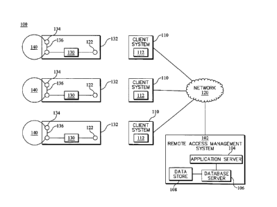
[0037] Exemplary embodiments of remote access control systems in accordance
with the
present invention will now be described with reference to the drawings.
[0038] Referring now to FIG. 1, a schematic diagram illustrating an example
network
architecture within which exemplary embodiments of the present invention can
be implemented
is illustrated. It should of course be understood that FIG. 1 is provided as
an example, not as an
architectural or environmental limitation for different embodiments of the
present invention, and
therefore, the particular elements depicted in FIG. 1 should not be considered
limiting with
regard to the environments within which exemplary embodiments of the present
invention may
be implemented.
[0039] In the example architecture depicted in FIG. 1, an access control
environment 100 is
provided as a client/server environment that includes a remote access
management system 102
that is commonly accessed by each user of the system through operation of any
of a plurality of
portable user, or client, systems 110 that are configured to operatively
couple to the remote
access management system via a communication network 120.
[0040] Exemplary access control environment 100 of FIG. 1 further includes a
plurality of
access points 130 for respectively controlling access to a plurality of
secured areas 140. In
exemplary embodiments, each access point 130 includes an entry control system
132 comprising
one or more wireless devices capable of receiving wireless signals from client
systems 110 and
communicating with a locking mechanism 134, which, in some embodiments,
comprise a device
-9-
CA 3080097 2020-05-07
that is communicatively coupled to the entry control system and capable of
locking and/or
controlling access to the corresponding secured area for the access point. A
physical barrier 136
is connected to locking mechanism 134 and such that, when locking mechanism
134 frees the
lock securing the barrier 136, the barrier is able to be opened. In the
example architecture
illustrated in FIG. 1, each of the access points 130 includes a local
connection 122 and the client
systems 110 are further configured to communicate with a respective access
point 130 by
establishing a communication channel with the respective local connection 122,
as discussed
further below.
[0041] In the example architecture illustrated in FIG. 1, the remote access
management
system 102 includes an application server 104 and a database server 106 that
is coupled to a data
store 108. Each of the application server 104 and the database server 106 are
operatively coupled
to network 120. As will be described in greater detail herein, the application
server 104 may be
implemented to manage access information maintained in the data store 108 by
the database
server 106 for each respective area secured by the access points 130 and
communicate, via the
network 120, with client systems 110, which, as noted above, are also
configured to connect to
the network 120. The application server 104 may therefore comprise, for
example, one or more
server computers with high speed connections to the network 120.
[0042] In exemplary embodiments, each client system 110 is a portable user
terminal or
other portable client device configured to access services provided within the
remote access
management system 102 via a network-based application (also referred to herein
as a network
service) implemented by the application server 104. For example, client
systems may be
implemented with software for one or more corresponding client applications
that may be
executed on the client system to allow users to interact with the application
server 104 to access
-10-
CA 3080097 2020-05-07
services provided within the remote access management system 102. Such client
applications
may also be referred to as client modules, or simply clients, and may be
implemented in a variety
of ways. In exemplary embodiments, such client applications can be implemented
as any of a
myriad of suitable client application types, which range from proprietary
client applications
(thick clients) to web-based interfaces in which the user agent function is
provided by a web
server and/or a back-end program (for example, a CGI program).
[0043] In some exemplary embodiments, the access control environment 100
includes
additional servers, clients, and other devices not shown in FIG. 1. The
particular architecture
depicted in FIG. 1 is provided as an example for illustrative purposes and, in
exemplary
embodiments, any number of client systems may be connected to any number of
different
servers within the remote access management system 102 at any given time via
the network 120,
and the remote access management system 102 can comprise multiple server
components and
data stores located within a single server system or within multiple server
systems, where the
multiple server systems are integrated with or accessible by users of the
client systems 110 as a
distributed server system via the network 120. In exemplary embodiments, the
remote access
management system 102 may also include at least one third-party server system,
which may be
utilized to enable functionality that may be accessed and utilized by the
application server 104 to
provide and/or enhance the access management services discussed herein.
[0044] In some exemplary embodiments, the network 120 can be configured to
facilitate
networked communications between the management system 102 and client systems
110, as well
as communications with and between other devices and computer systems coupled
together
within the access control environment 100, by any suitable wired (including
optical fiber),
wireless technology, or any suitable combination thereof, including, but not
limited to, personal
-11-
CA 3080097 2020-05-07
7
area networks (PANs), local area networks (LANs), wireless networks, wide-area
networks
(WAN), the Internet (a network of heterogeneous networks using the Internet
Protocol, IP), and
virtual private networks, and the network may also utilize any suitable
hardware, software, and
firmware technology to connect devices such as, for example, optical fiber,
Ethernet, ISDN
(Integrated Services Digital Network), T-1 or T-3 link, FDDI (Fiber
Distributed Data Network),
cable or wireless LMDS network, Wireless LAN, Wireless PAN (for example, IrDA,
Bluetooth,
Wireless USB, Z-Wave and ZigBee), HomePNA, Power line communication, or
telephone line
network. Such a network connection can include intranets, extranets, and the
Internet, may
contain any number of network infrastructure elements including routers,
switches, gateways,
etc., can comprise a circuit switched network, such as the Public Service
Telephone Network
(PSTN), a packet switched network, such as the global Internet, a private WAN
or LAN, a
telecommunications network, a broadcast network, or a point-to-point network,
and may utilize a
variety of networking protocols now available or later developed including,
but not limited to the
Transmission Control Protocol/Internet Protocol (TCP/IP) suite of protocols
for communication.
[0045] In exemplary embodiments, the application server 104, the database
server 106, and
any other servers employed within the management system 102 and third-party
servers utilized
within the access control environment 100 can be implemented within any
suitable computing
system or systems such as a workstation computer, a mainframe computer, a
server system (for
example, SUN ULTRA workstations running the SUN operating system, IBM RS/6000
workstations and servers running the AIX operating system, or an IBM zSeries
eServer running
z/OS, z/VM, or LINUX OS), a server cluster, a distributed computing system, a
cloud based
computing system, or the like, as well as any of the various types of
computing systems and
devices described below with reference to the client systems 110. Management
system 102 may
-12-
CA 3080097 2020-05-07
be implemented using any of a variety of architectures. For example, the
application server 104
and the database server 106 may also be implemented independently or as a
single, integrated
device. While the exemplary embodiment illustrated in FIG. 1 depicts the
application server 104
and the database server 106 as individual components, the applications
provided by these
servers, or various combinations of these applications, may actually be server
applications
running on separate physical devices. In this regard, the management system
102 may comprise
a number of computers connected together via a network and, therefore, may
exist as multiple
separate logical and/or physical units, and/or as multiple servers acting in
concert or
independently, wherein each server may be comprised of multiple separate
logical and/or
physical units. In exemplary embodiments, management system 102 can be
connected to the
network 120 through a collection of suitable security appliances, which may be
implemented in
hardware, software, or a combination of hardware and software.
[0046] In the exemplary architecture illustrated in FIG. 1, the application
server 104 is
communicatively coupled to the database server 106. The database server 106 is
connected to the
data store 108, which is implemented as a network storage device capable of
storing data in a
structured or in an unstructured format. In exemplary embodiments, the data
store 108 may
comprise a plurality of databases that are maintained by the database server
106, accessed by the
application server 104 via database services provided at a front end by the
database server 106,
and store data representing a variety of information that is utilized in
providing the access
management services offered via the network service provided by the
application server 104, as
described in greater detail below.
[0047] As used herein, the term "data store," "data storage unit," storage
device", and the
like can to any suitable memory device that may be used for storing data,
including manual files,
-13-
CA 3080097 2020-05-07
machine-readable files, and databases. In exemplary embodiments, the
application server 104,
the database server 106, and the data store 108 may implemented together a
single computing
device, implemented within a plurality of computing devices locally coupled to
each other via a
suitable communication medium, such as a serial port cable, telephone line, or
wireless
frequency transceiver, implemented within a plurality of computing devices
remotely coupled to
each other via the network 120, or any suitable combination thereof.
[0048] The portable client systems 110 are computer devices to which one or
more users
have access and that are also configured to connect to the network 120 and may
access remote
access management system 102 via the network 120 to operate as clients to the
remote access
management system 102. In exemplary embodiments, the client systems 110 are
each further
configured to establish a communication channel with and thereby communicate
with one or
more of access points 130 using the respective local connection 122 for the
access point. It
should be noted that the term "user" is used herein to refer to one who uses a
computer system,
such as one of the client systems 110. As described in greater detail below,
client systems 110
are each operable by such users to access management system 102 via network
120 and act as
clients to access services offered by the network service provided by the
server system within the
access control environment 100. For this purpose, as noted above, each client
system 110
includes a respective client application 112 that executes on the client
system 110 and allows a
user to interact with the management system 102 via the application server
104.
[0049] Client systems 110 can represent any type of portable device capable of
communicating with the application server 104 and access points 130. While
client systems 110
are depicted in FIG. 1 as a single device, such depiction is for illustrative
purposes only, and
-14-
CA 3080097 2020-05-07
each of the client systems can represent a single portable device or a
plurality of portable devices
capable of communicating with the application server 104 and access points
130.
[0050] In exemplary embodiments, the computer systems of client systems 110
can be any of
a wide range of suitable portable or handheld computing devices such as one or
more handheld
computers, laptops, tablet computers, netbook computers, two-way pagers,
cellular telephones,
mobile handsets, smart phones, computer digital devices such as Personal
Digital Assistants
(PDAs), and the like, or any other suitable portable or handheld information
processing devices.
In general exemplary embodiments, a portable or handheld electronic device
that is utilized as a
client system 110 within access control environment 100 may comprise a small
general
computing device having a processing unit that is capable of running one or
more application
programs, a display, an input mechanism that is typically something other than
a full-size
keyboard and wireless communication capability. The input mechanism may be,
for example, a
keypad, a touch-sensitive screen, a track ball, a touch-sensitive pad, a
miniaturized QWERTY
keyboard, or the like. An exemplary computer system for client systems 110 is
described in
greater detail below with reference to FIG. 6.
[0051] In general, during operation within the exemplary access control
environment 100, a
client system 110 first establishes a connection to the remote access
management system 102 via
network 120. Once the connection has been established, the connected client
system 110 may
directly or indirectly transmit data to and access content from the
application server 104. A user
accessing the application server 104 through the connected client system 110
can thereby to use
the client application 112 to access services provided by the application
server 104, which are
described in greater detail below, via a user interface implemented by the
client application 112
-15-
CA 3080097 2020-05-07
within which the client application 112 renders the information served by the
application server
104.
[0052] In exemplary embodiments, the application server 104 can implement the
network
service as a non-web client application (such as a mobile application), a web
client application,
or both to provide the services accessed by client systems 110 within the
management system
102, and client applications 112 can correspondingly be implemented as non-web
client
applications, web client applications, or both for operation by users of the
client systems 110 to
interact with the application server 104 and access the services provided
thereby. For example,
the application server 104 can comprise a web server configured to provide a
web application for
the respective client applications implemented on client systems 110 that are
configured to
provide web-based user interfaces for utilizing the services provided by the
web server. For
instance, the user interfaces of client applications implemented on client
systems 110 can be
configured to provide various options corresponding to the functionality
offered in exemplary
embodiments described herein through suitable user interface controls (for
example, by way of
menu selection, point-and-click, dialog box, or keyboard command). In one
general example, the
user interfaces may provide "send" or "submit" buttons that allow users of
client applications to
transmit requested information to application server 104. The user interfaces
can be
implemented, for example, as a graphical user interface (GUI) that renders a
common display
structure to represent the network service provided by application server 104
for a user of a
client platform.
[0053] In exemplary embodiments, client applications 112 and the application
server 104
may be configured to utilize cryptographic protocols so that communications
and information
exchanged between the management system 102 and the client systems 110 can be
encrypted
-16-
CA 3080097 2020-05-07
and decrypted using one or more encryption methods and sent over a secure
network connection
for purposes of, for example, preventing unauthorized access to management
system 102 and
privacy.
[0054] Referring now to FIG. 2, a block diagram illustrating an exemplary
embodiment of a
remote access management system 102 is provided. As illustrated in FIG. 2, an
application
server 104 is implemented to provide a plurality of services, including an
account management
service 1042, a secured area management service 1044, and a secured area
access service 1046.
[0055] In exemplary embodiments, the application server 104 can implement the
services
offered thereby to provide a respective set of functionality for each of
various types of users (for
example, property owners, property managers, property staff, residential
tenants, commercial
tenants, guests, and the like). Some of the functionality offered by the
application server 104 can
be commonly applicable to and accessible by all types of users, while other
functionality can be
applicable to and accessible only by specific types of users. In addition, a
particular user account
can have any number of authorized users. As an example, a user account
established for a
property manager can have the property manager as one of its users, but it can
also have staff
working for.the property manager as other authorized users. For purpose of
illustration, there can
be a designated user (for example, an account administrator) who is
responsible for managing
the account. The administrator can be provided with greater access rights
within management
system 102 with respect to the account. In exemplary embodiments, the
particular client
applications 112 or the particular client systems 110 (shown in FIG. 1) that
are utilized for
accessing application server 104 can be respective to and customized for each
type of user
account. For example, the particular client application 112 that is utilized
for each type of
-17-
CA 3080097 2020-05-07
account can implement a platform that is specific to the functionality offered
for that type of
account.
[0056] As further illustrated in exemplary embodiment of FIG. 2, and as will
also be
described in greater detail below, a data store 108 comprises a plurality of
databases that are
maintained and accessible by the application server 104 via a database server
106, including a
user profile database 108a, a secured area database 108b, and one or more
additional databases
108c that may be used for storing any other suitable information that may be
utilized by the
management system 102 (for example, system usage data, audit trail data, data
used internally
within the system by application server 104, and the like). In exemplary
embodiments, the
various databases maintained within the data store 108 can be maintained as
groups within one
or more larger databases or maintained individually.
[0057] As discussed below, the database server 106 can be configured to
maintain various
types of information records within the plurality of databases. An information
record may be, for
example, a program and/or data structure that tracks various data related to a
corresponding type
of information record. As used herein, the terms "data," "content,"
"information" and similar
terms may be used interchangeably to refer to data capable of being captured,
transmitted,
received, displayed, and/or stored in accordance with various example
embodiments. Thus, use
of any such terms should not be taken to limit the spirit and scope of the
disclosure. Further,
where a computing device is described herein to receive data from another
computing device, it
will be appreciated that the data may be received directly from the another
computing device or
may be received indirectly via one or more intermediary computing devices,
such as, for
example, one or more servers, relays, routers, network access points, base
stations, and/or the
like. Similarly, where a computing device is described herein to send data to
another computing
-18-
CA 3080097 2020-05-07
device, it will be appreciated that the data may be sent directly to the
another computing device
or may be sent indirectly via one or more intermediary computing devices, such
as, for example,
one or more servers, relays, routers, network access points, base stations,
and/or the like.
[0058] As noted above, different types of users can access the remote access
management
system 102. As such, the application server 104 can be configured to maintain
and manage
account information records for different types of users that register with
the system according to
certain categories of accounts. In the present exemplary embodiment, the user
profile database
108a is used to maintain account information records for secured area managers
that are
registered with the management system 102 to grant access privileges for one
or more secured
areas to secured area entrees registered with the system and, likewise, for
secured area entrees
that are registered with the management system 102 to receive access
credentials in accordance
with access privileges granted by secured area managers registered with the
system.
[0059] For each user for which a user account is registered with the
management system
102, various items of information relevant to the user, such as name, address
or location
information, contact information, billing information, unique identification
information for one
or more client systems 110 utilized by the user, such as an International
Mobile Subscriber
Identity (IMSI) number associated with the subscriber identity module (SIM)
card of mobile
device, and any other suitable identifying information, as well as a unique
user name and
password associated with the account that can be used to log into the account,
can be included in
the respective account information record for the user that is maintained
within the user profile
database 108a. The account information record for each user can also be
associated with a
unique user account identifier within the user profile database 108a that is
used by the
application server 104 for performing various operations.
-19-
CA 3080097 2020-05-07
[0060] For each secured area manager user for which an account is registered
and
maintained within the user profile database 108a, various additional items of
information
relevant to the secured area manager may also be included in the respective
account information
record for the user that is maintained within the user profile database 108a,
such as unique
secured area identifiers for the particular secured areas within the access
control environment
100 for which the secured area manager has rights to grant access privileges,
unique user account
identifiers for secured area entree users of the management system 102 for
which the secured
area manager can grant access privileges for secured areas for which the
secured area manager
has rights to grant access privileges, and a list of access privileges that
the secured area manager
has granted for secured area grantee users with respect to secured areas for
which the secured
area manager has rights to grant access privileges. In exemplary embodiments,
the list of access
privileges that are maintained within the respective account information
record for each secured
area manager that is maintained within the user profile database 108a can
include an indication
of whether each access privilege is currently active or inactive or,
alternatively, can only include
access privileges that are currently active.
[0061] For each secured area entree user for which an account is registered
and maintained
within the user profile database 108a, various additional items of information
relevant to the
secured area manager may also be included in the respective account
information record for the
user that is maintained within the user profile database 108a, such as unique
user account
identifiers for the secured area manager users of that management system 102
that can grant
access privileges for secured areas within the access control environment 100,
unique secured
area identifiers for secured areas for which the secured area entree user can
be granted access
privileges, a list of access privileges for secured areas that have been
granted to the secured area
-20-
CA 3080097 2020-05-07
entree user by the secured area managers that are registered with the system,
a set of access
credential information that has been provided or is available to the secured
area entree user for
each secured area for which access privileges have been granted to the secured
area entree user
by secured area managers that are registered with the system, and user access
history logs for the
user pertaining to past user accesses of secured areas within the access
control environment 100,
which may include profiling of client system usage, client application usage,
and application
data; historical data about any of these items of information related to the
client system 110 used
by the user; and any other contextual information, available to or stored in
the client system 110,
in any combination.
[0062] In exemplary embodiments, the list of access privileges and the
corresponding set of
access credential information that are maintained within the respective
account information
record for each secured area entree user that is maintained within the user
profile database 108a
can include an indication of whether each access privilege or set of access
credential information
is currently active or inactive or, alternatively, can only include access
privileges and/or access
credential information that are currently active. In exemplary embodiments,
access credentials
can comprise, for instance, passwords, security codes, digital certificates,
and the like. In further
embodiments, access credentials can comprise computer readable and/or
executable files that can
be transferred to and stored on the client systems 110.
[0063] In the exemplary embodiment depicted in FIG. 2, the secured area
database 108b is
used to maintain information records for secured areas within the access
control environment
100 that have been registered within the management system 102 for which
access privileges can
be granted to secured area entrees registered with the system by secured area
managers
registered with the system. For each secured area that has been registered
with the management
-21-
CA 3080097 2020-05-07
system 102, various items of information relevant to the secured area, such as
area or property
name, address or location information, information describing the
corresponding access point
130 for the secured area, and any other suitable identifying information, as
well as the unique
user account identifier for each registered secured area manager that has
rights to grant access
privileges to registered secured area entrees for the secured area, the unique
user account
identifier for each registered secured area entree to which access privileges
for the secured area
can be granted by registered secured area entrees, a list of access privileges
for the secured area
that have been granted to registered secured area entree users by registered
secured area
managers, a set of access credential information that has been provided to
each secured area
entree user for which access privileges have been granted to the secured area
by registered
secured area managers, and one or more sets of additional access credential
information that is
available to be provided to secured area entree users for which access
privileges have been
granted to the secured area by registered secured area managers or upon access
privileges being
granted to secured area entree users for the secured area by registered
secured area managers,
can be included in the respective information record for the secured area that
is maintained
within secured area database 108b. The information record for each secured
area can also be
associated with a unique secured area identifier within the secured area
database 108b that is
used by the application server 104 for performing various operations.
[0064] In exemplary embodiments, and referring once again to FIG. 1 in
addition to FIG. 2,
a user of a client system 110 within the access control environment 100 may be
required to first
install a client application 112 on the client system 110 before the client
system 110 can access
the services provided by application server 104. For example, upon the user
initiating the
installation of the client application 112, the client system 110 can download
the client
-22-
CA 3080097 2020-05-07
application 112 from the remote access management system 102 or from a
separate content
server. Upon receipt of the client application 112, the client system 110 can
operate to install the
client application 112.
[0065] In exemplary embodiments, when any user, regardless of whether the user
is
registered with the management system 102 with any type of user account or a
non-registered
user, operates a client system 110 to access application server 104 (for
example, by launching a
native client application or by using a web browser to submit a URL that
provides a network
address for application server 104), the application server 104 can be
configured with a default
setting that directs the user to a home page within the user interface
implemented by the
application server 104 for the services provided by the application server
104, at which the user
is presented with various options through the user interface to access the
various functions that
are provided by the account management service 1042, the secured area
management service
1044, and/or the secured area access service 1046 and available to the
particular user.
[0066] In such embodiments, a secured area entree user may be required to
first register with
the management system 102 and thereby establish a respective account
information record
within the user profile database 108a to be able to request and receive access
credentials from the
application server 104 via the secured area access service 1046. In exemplary
embodiments, a
user operating a client system 110 to access application server 104 via a
corresponding client
application 112 executing on the client system 110 may be provided with a user
interface
element within the user interface implemented by the application server 104
that is accessible by
the user to initiate a registration with the management system 102 as a
secured area entree user,
and the application server 104 may be configured to, in response to a user
accessing the user
interface element, provide further user interface controls for allowing the
user to initiate a
-23-
CA 3080097 2020-05-07
registration session with the account management service 1042 to register a
user account with
the management system 102.
[0067] The account management service 1042 may be configured, for example, to
implement a user interface that includes a series of pages with user interface
controls accessible
by the user to guide the user through the account registration process and
prompt the user to
input various types of information to be maintained by the database server 106
within a
respective account information record that is established for the user within
user profile database
108a. The account management service 1042 can be configured to access the
database server 106
to create the respective account information record for the user within the
user profile database
108a based on the information input by the user during the registration
process. The account
management service 1042 can be further configured to generate the unique
customer account
identifier for the created account information record, which may be used, for
example, to index
and reference the created account information record within the database
server 106. The created
account information record can also be identified with a unique user name and
protected by a
password, which can be used by the user to log into the associated user
account when accessing
the application server 104.
[0068] The system shown in FIG. 3 includes an exemplary embodiment of the
system used
in applications described herein. As illustrated in FIG. 3, a client system
110 is initially provided
in communication with the remote access management system 102 via connection
301. A pass
code 304 is a code authorizing a user to enter one or more of the secured
areas 140 shown in
FIG. 1 which is blocked by a physical barrier (e.g., gate) 136 with a locking
mechanism 134
illustrated in FIG. 3. The pass code 304 is transferred from the remote access
management
system 102 to a memory 302 on client system 110. Transfer may take place using
any number of
-24-
CA 3080097 2020-05-07
methods including those known in the art that provide a connection 301. After
transfer of the
pass code 304 to the client system 110, the pass code 304 may be stored in the
memory 302 of
client system 110 consistent with the description herein. As an example, it
may be stored in a
client application 112.
[0069] Once the pass code 304 is resident on the client system 110, the client
system 110
may then be physically brought in proximity to the access point 130 and
connected via a local
connection 122. As described herein, local connection 122 is only effective
within a limited
range. The local connection 122 may also be a low power protocol in addition
to having a
limited range. For example, BlueTooth may be a protocol used to transfer
data. LoRa may be
a protocol used to transfer data. NFC Logical Link Control Protocol (LLCP) may
also be used.
As yet another alternative, any protocol compliant with IEEE 802.2 may be
used. For certain
embodiments discussed herein, a single direction data flow may be sufficient.
For other
embodiments, a bidirectional data flow standard may be desirable. Other low
power and low
distance of transmission protocols may be used in the alternative or in
addition to one of the
above protocols.
[0070] Using one of the above described communication protocols, the client
system 110
transmits the pass code 304 to the access point 130. The pass code 304 is then
compared against
pass code 308, which is the same code but already provided to the entry
control system 132. As
an example, pass code 308 may be stored in a memory provided on the access
point 130.
Alternatively, pass code 308 may be a pseudorandom code that is generated
based on a variety of
known methods such as hashing with a variable such as time. In such an
instance, pass code 304
will likewise be generated on the client system 110 to provide the correct
matching code. Pass
-25-
CA 3080097 2020-05-07
code 308 may also be a hard wired or embedded code assigned to a specific
access point 130,
which is part of a specific entry control system 132.
[0071] Assuming that the access point 130 compares pass code 304 and pass code
308 and
verifies that they are the same, it then grants access to the user. In
particular, the access point 130
may unlock the gate 136 via triggering the locking mechanism 134.
[0072] Referring still to FIG. 3, the exemplary system may, in some
embodiment, utilize
multiple auxiliary pass codes in addition to or in replacement of the pass
codes 304, 308
discussed above.
[0073] In another embodiment illustrated in FIG. 3, primary auxiliary codes
310 and 312
may be used in addition to pass codes 304 and 308. In particular, primary
auxiliary codes 310
and 312 may be additional information previously provided to the entry control
system 132 that
acts to provide additional verification (i.e., verification codes) that a user
providing pass code
304 to the entry control system 132 is an authorized user. As an example, a
primary auxiliary
code 310 may be a specific code associated with a specific access point 130,
e.g., a serial
number, that provides an additional layer of security when employed.
[0074] In another embodiment illustrated in FIG. 3, secondary auxiliary codes
314 and 316
may be yet another set of codes used to provide additional security to the
system. In this
embodiment, entry control system 132 includes memory 306 capable of storing
and retrieving
more than one code in memory 306. The secondary auxiliary code 316 may be a
predefined code
that is part of a list known to the remote access management system 102. Once
prior authorized
users are provided with the pass code 304 and the primary auxiliary code 310
(which
corresponding pass code 308 and primary auxiliary code 312), the remote access
management
system 102 will assign the next authorized user a next assigned code from the
list stored in
-26-
CA 3080097 2020-05-07
memory 306, e.g., secondary auxiliary code 316. In this manner, it is possible
to have a plurality
of predetermined codes available to assign to users to the extent that the
memory 306 may hold
additional codes.
[0075] In yet another embodiment illustrated in FIG. 3, tertiary auxiliary
codes 318 and 320
may provide yet another additional layer of security. Like one of the
proceeding embodiments, it
is assumed for this embodiment that entry control system 132 includes memory
306 that is
capable of storing and retrieving a code. In addition, the memory 306 as
described in this
embodiment is further capable of writing a code as tertiary auxiliary code 320
into memory 306.
In this embodiment, it is assumed that a prior user received at least the pass
code 304 and the
tertiary auxiliary code 318. It is further assumed that upon authorization
using only the pass code
304, that the tertiary auxiliary code 318 is also transferred to the entry
control system 132 and
stored in memory 306 as tertiary auxiliary code 320. The next instance where
the remote access
management system 102 issues a code for an authorized user, it then issues the
tertiary auxiliary
code 318 which is the corresponding code to the previously stored tertiary
auxiliary code 320. As
such, as described in this embodiment it is possible to dynamically generate a
code in advance
(e.g., tertiary auxiliary code 318), have a user transfer the code generated
in advance, and have
the code pre-stored in memory 306 for use by a subsequent user. Although the
system in FIG. 3
only illustrates three auxiliary codes, the number of auxiliary pass codes is
not limited and can
be expanded up to the capacity of the memory 306 of the entry control system
132.
[0076] In yet another embodiment illustrated in FIG. 3, special use, or
temporary, codes 322,
324 may be generated by the remote access management system 102 for a special
use case. As
an example, if vendor or service personal are to be authorized access to only
part of a specific
secured area 140, then a temporary code 322 may be generated and matched to
temporary code
-27-
CA 3080097 2020-05-07
324 by the entry control system 132. It will now be apparent to one of
ordinary skill in the art
that a number of variations of special use, or temporary, codes may be
possible. For instance, if
the entry control system 132 further includes an internal clock, special use
codes 322, 324 may
only be authorized to provide access between a certain predetermined time
interval. Temporary
codes 322, 324 may also be provided and rewritten on a periodic (e.g., daily)
basis to facilitate
vendor or service access.
[0077] It will also now be apparent to one of ordinary skill that the above
described
embodiments are not necessarily exclusive and may be used in different
combinations with each
other without varying from the scope of embodiments described herein. For
example, in the case
of a bidirectional data flow, it would also be possible for the entry control
system 132 to transmit
messages via other codes to the user (e.g., via the client system 110), who
will then relay those
codes back to the remote access management system 102 when the client system
110 again
connects with the network 120. As an example, the entry control system 132
could transmit a
low battery warning to the remote access management system 102, which could,
in turn provide,
a notice to an administrator of the remote access management system 102 that
the low battery
warning was transmitted from a client system 110 that had been brought into
proximity with a
particular access point of the entry control system 132. In addition or in the
alternative, the entry
control system 132 could also upload a log of activity on the entry control
system 132 to a client
system 110 brought into proximity with the entry control system 132. Like the
variation
discussed above, these logs could then be sent back to the remote access
management system
102 via the client system 110 once the client system 110 is able to connect
with the network
120. Other similar status information about the entry control system 132 can
likewise be sent
from the entry control system 132 to the remote access management system 102.
-28-
CA 3080097 2020-05-07
=
[0078] Further discussion of a method consistent with the above described
systems and
apparatuses is illustrated in FIG. 4. The method 400 shown in FIG. 4
illustrates one exemplary
implementation of the embodiments described above. Method 400 begins with
block 402 in
which the remote access management system 102 provides a code to a client
system 110 via the
network 120. As is already discussed above, the network 120 may be any of a
variety of network
systems capable of connecting to the client system 110. The connection between
the client
system 110 and the network 120 may be accomplished by any of a variety of
conventional
systems.
[0079] Once the code has been loaded onto the client system 110, the next step
is illustrated
as block 404 in which the client system 110 transmits the code present on the
client system 110
to an entry control system 132. This occurs when the client system 110 is
brought into proximity
with the entry control system 132. As already highlighted above, communication
between the
client system 110 and the entry control system 132 is accomplished by a
protocol capable of
transmitting over limited distances. As an example, a near field communication
protocol might
be used. Other protocols requiring close proximity to the receiver may also be
used. In addition,
a low power protocol may be used to minimize the energy required by the entry
control system
132.
[0080] The method then proceeds to block 406, in which the entry control
system 132
compares the code received from the client system 110 to a stored code on the
entry control
system 132. As an example, the entry control system 132 may compare pass code
304 to pass
code 308 as illustrated in FIG. 3. As illustrated by comparator 408, the entry
control system 132
then compares these codes. If the codes match, the system proceeds to block
410 in which the
entry control system 132 grants access to the secured area 140 illustrated in
FIG. 1. With
-29-
CA 3080097 2020-05-07
=
reference to FIGS. 1 and 3, the entry control system 132, which is in
communication with a
locking mechanism 134, will trigger the locking mechanism 134 and free a lock
securing barrier
136. The authorized user is then granted access to secured area 140. In
contrast, if the codes do
not match, the system proceeds to block 412 in which the entry control system
132 denies access
to the secured area 140.
[0081] FIG. 5 illustrates method 500 that includes variations of the different
embodiments
discussed above. Method 500 begins with block 502 in which the remote access
management
system 102 provides multiple codes to the client system 110 via the network
120. Examples of
the multiple codes are illustrated in FIG. 3, and may include codes 304, 308,
310, 312, 314, 316,
318, 320, 322, and 324. As will be discussed in more detail below, these codes
may be
transparent to the user. Certain codes, however, may not be transparent and
may be stored on the
client system 110, but are hidden, or inaccessible, to the user.
[0082] Proceeding to block 504, the client system 110 is then brought in
proximity with the
entry control system 132. The multiple codes are then transferred to the entry
control system 132
once the client system 110 and the entry control system 132 are in
communication.
[0083] With reference to some exemplary implementations of the embodiments
discussed
above, block 510 illustrates when the entry control system 132 recognizes that
there is at least
one code provided of the multitude of codes as a temporary code. These
temporary codes may be
issued, for example, to a vendor. Alternatively, the temporary code may be a
code indicating a
new user.
[0084] With reference to some other exemplary implementations of the
embodiments
discussed above, block 520 illustrates when the entry control system 132
recognizes at least one
of the codes as a verification code. As discussed above, verification codes
may be used to
-30-
CA 3080097 2020-05-07
provide an additional level of security. As also illustrated in block 520, at
least one of the
multiple codes transferred to the entry control system 132 is also recognized
as an access code.
As used with respect to this embodiment, an access code is a code associated
with an authorized
user. As there may be multiple authorized users, the multiple codes
transferred to the entry
control system 132 may include multiple additional codes that are each
associated with one of
the multiple authorized users.
[0085] As illustrated in block 522, the verification code is then checked
against verification
codes stored on the entry control system 132. If the verification code is not
found to be valid,
access is denied as shown in block 524.
[0086] With reference to still other exemplary implementations of the
embodiments
discussed above, block 530 illustrates when the entry control system 132
recognizes at least two
codes as authorizing access to the secured area. As discussed further below,
one of the
authorizing codes may not be transparent to the user, i.e., may be hidden from
the user in a
nontransparent portion of the application. If such a code is detected, as
shown in block 532, the
entry control system 132 identifies the current and future access code. As
shown in block 534,
the future access code is then stored on the entry control system 132 for
future access by a future
user. The future access code may be stored on the client system 110, but may
not be transparent
to the user.
[0087] For each of the embodiments discussed above, eventually comparator
block 540 is
reached. At comparator block 540, the entry control system 132 compares the
codes provided by
the client system 110 against valid codes stored in the entry control system
132. Assuming that a
valid code has been provided by the user, the system grants access to the
secured area that is
-31-
CA 3080097 2020-05-07
illustrated in block 544. If a valid code has not been demonstrated by the
user, then access is
denied as shown in block 542.
[0088] FIG. 6 is a block diagram of an exemplary computer system 600 that can
be used for
implementing exemplary embodiments of the present invention. Computer system
600 includes
one or more processors, such as processor 604. Processor 604 is connected to a
communication
infrastructure 602 (for example, a communications bus, cross-over bar, or
network). Various
software embodiments are described in terms of this exemplary computer system.
After reading
this description, it will become apparent to a person of ordinary skill in the
relevant art(s) how to
implement the invention using other computer systems and/or computer
architectures.
[0089] Exemplary computer system 600 can include a display interface 608 that
forwards
graphics, text, and other data from the communication infrastructure 602 (or
from a frame buffer
not shown) for display on a display unit 610. Computer system 600 also
includes a main memory
606, which can be random access memory (RAM), and may also include a secondary
memory
612. Secondary memory 612 may include, for example, a hard disk drive 614
and/or a removable
storage drive 616, representing a floppy disk drive, a magnetic tape drive, an
optical disk drive,
etc. Removable storage drive 616 reads from and/or writes to a removable
storage unit 618 in a
manner well known to those having ordinary skill in the art. Removable storage
unit 618,
represents, for example, a floppy disk, magnetic tape, optical disk, etc.
which is read by and
written to by removable storage drive 616. As will be appreciated, removable
storage unit 618
includes a computer usable storage medium having stored therein computer
software and/or data.
[0090] In exemplary embodiments, secondary memory 612 may include other
similar means
for allowing computer programs or other instructions to be loaded into the
computer system.
Such means may include, for example, a removable storage unit 622 and an
interface 620.
-32-
CA 3080097 2020-05-07
Examples of such may include a program cartridge and cartridge interface (such
as that found in
video game devices), a removable memory chip (such as an EPROM, or PROM) and
associated
socket, and other removable storage units 622 and interfaces 620 which allow
software and data
to be transferred from the removable storage unit 622 to computer system 600.
[0091] Computer system 600 may also include a communications interface 624.
Communications interface 624 allows software and data to be transferred
between the computer
system and external devices. Examples of communications interface 624 may
include a modem,
a network interface (such as an Ethernet card), a communications port, a
PCMCIA slot and card,
etc. Software and data transferred via communications interface 624 are in the
form of signals
which may be, for example, electronic, electromagnetic, optical, or other
signals capable of
being received by communications interface 624. These signals are provided to
communications
interface 624 via a communications path (that is, channel) 626. Channel 626
carries signals and
may be implemented using wire or cable, fiber optics, a phone line, a cellular
phone link, an RF
link, and/or other communications channels.
[0092] In this document, the terms "computer program medium," "computer usable
medium," and "computer readable medium" are used to generally refer to media
such as main
memory 606 and secondary memory 612, removable storage drive 616, a hard disk
installed in
hard disk drive 614, and signals. These computer program products are means
for providing
software to the computer system. The computer readable medium allows the
computer system to
read data, instructions, messages or message packets, and other computer
readable information
from the computer readable medium. The computer readable medium, for example,
may include
non-volatile memory, such as Floppy, ROM, Flash memory, Disk drive memory, CD-
ROM, and
other permanent storage. It can be used, for example, to transport
information, such as data and
-33-
CA 3080097 2020-05-07
computer instructions, between computer systems. Furthermore, the computer
readable medium
may comprise computer readable information in a transitory state medium such
as a network link
and/or a network interface including a wired network or a wireless network
that allow a
computer to read such computer readable information.
[0093] Computer programs (also called computer control logic) are stored in
main memory
606 and/or secondary memory 612. Computer programs may also be received via
communications interface 624. Such computer programs, when executed, can
enable the
computer system to perform the features of exemplary embodiments of the
present invention as
discussed herein. In particular, the computer programs, when executed, enable
processor 604 to
perform the features of computer system 600. Accordingly, such computer
programs represent
controllers of the computer system.
[0094] Aspects of exemplary embodiments of the present invention described
herein can be
implemented using one or more program modules and data storage units. As used
herein, the
term "modules", "program modules", "components", "systems", "tools",
"utilities", and the like
include routines, programs, objects, components, data structures, and
instructions, or instructions
sets, and so forth that perform particular tasks or implement particular
abstract data types. As can
be appreciated, the modules refer to computer-related entities that can be
implemented as
software, hardware, firmware and/or other suitable components that provide the
described
functionality, and which may be loaded into memory of a machine embodying an
exemplary
embodiment of the present invention. Aspects of the modules may be written in
a variety of
programming languages, such as C, C++, Java, etc. The functionality provided
by modules used
for aspects of exemplary embodiments described herein can be combined and/or
further
partitioned.
-34-
CA 3080097 2020-05-07
[0095] As used herein, the terms "data storage unit," "data store", "storage
unit", and the like
can refer to any suitable memory device that may be used for storing data,
including manual
files, machine readable files, and databases. The modules and/or storage units
can all be
implemented and run on the same computing system (for example, the exemplary
computer
system illustrated and described below) or they can be implemented and run on
different
computing systems. For example, one or modules can be implemented on a
personal computer
operated by a user while other modules can be implemented on a remote server
and accessed via
a network.
[0096] In exemplary embodiments, the client applications utilized in exemplary
embodiments of the present invention can be configured for incorporation
within any suitable
network computing environment as a plug-in, add-on, or extension. As used
herein, the term
"plug-in" can refer to a software application or module program, or one or
more computer
instructions, which may or may not be in communication with other software
applications or
modules, that interacts with a host application to provide specified
functionality, and which may
include any file, image, graphic, icon, audio, video, or any other attachment.
In other exemplary
embodiments, the client applications can be implemented as a standalone
program that is run as a
separate computer process, a portable application, a native component of a
software tool, a part
of a software bundle, or any other suitable implementation.
[0097] In the preceding description, for purposes of explanation, numerous
specific details
are set forth in order to provide a thorough understanding of the described
exemplary
embodiments. Nevertheless, one skilled in the art will appreciate that many
other embodiments
may be practiced without these specific details and structural, logical, and
electrical changes may
be made.
-35-
CA 3080097 2020-05-07
[0098] Some portions of the exemplary embodiments described above are
presented in terms
of algorithms and symbolic representations of operations on data bits within a
processor-based
system. The operations are those requiring physical manipulations of physical
quantities. These
quantities may take the form of electrical, magnetic, optical, or other
physical signals capable of
being stored, transferred, combined, compared, and otherwise manipulated, and
are referred to,
principally for reasons of common usage, as bits, values, elements, symbols,
characters, terms,
numbers, or the like. Nevertheless, it should be noted that all of these and
similar terms are to be
associated with the appropriate physical quantities and are merely convenient
labels applied to
these quantities. Unless specifically stated otherwise as apparent from the
description, terms such
as "executing" or "processing" or "computing" or "calculating" or
"determining" or the like,
may refer to the action and processes of a processor-based system, or similar
electronic
computing device, that manipulates and transforms data represented as physical
quantities within
the processor-based system's storage into other data similarly represented or
other such
information storage, transmission or display devices.
[0099] Exemplary embodiments of the present invention can be realized in
hardware,
software, or a combination of hardware and software. Exemplary embodiments can
be realized
in a centralized fashion in one computer system or in a distributed fashion
where different
elements are spread across several interconnected computer systems. Any kind
of computer
system ¨ or other apparatus adapted for carrying out the methods described
herein ¨ is suited. A
typical combination of hardware and software could be a general-purpose
computer system with
a computer program that, when being loaded and executed, controls the computer
system such
that it carries out the methods described herein.
-36-
CA 3080097 2020-05-07
[0100] Exemplary embodiments of the present invention can also be embedded in
a
computer program product, which comprises all the features enabling the
implementation of the
methods described herein, and which ¨ when loaded in a computer system ¨ is
able to carry out
these methods. Computer program means or computer program as used in the
present invention
indicates any expression, in any language, code or notation, of a set of
instructions intended to
cause a system having an information processing capability to perform a
particular function
either directly or after either or both of the following: (a) conversion to
another language, code
or, notation; and (b) reproduction in a different material form.
[0101] A computer system in which exemplary embodiments can be implemented may
include, inter alia, one or more computers and at least a computer program
product on a
computer readable medium, allowing a computer system, to read data,
instructions, messages or
message packets, and other computer readable information from the computer
readable medium.
The computer readable medium may include non-volatile memory, such as ROM,
Flash
memory, Disk drive memory, CD-ROM, and other permanent storage. Additionally,
a computer
readable medium may include, for example, volatile storage such as RAM,
buffers, cache
memory, and network circuits. Furthermore, the computer readable medium may
comprise
computer readable information in a transitory state medium such as a network
link and/or a
network interface, including a wired network or a wireless network, that allow
a computer
system to read such computer readable information.
[0102] FIG. 7 illustrates one exemplary client application 112 interacting
with the remote
access management system 102 in more detail. In at least one embodiment, the
client application
112 will have a transparent section 702 and a hidden section 704. Transparent
section 702 and
hidden section 704 may each function as a virtual computer. In other words,
each of the sections
-37-
CA 3080097 2020-05-07
702, 704 will function as a virtual computer including virtual memory, virtual
JO, and a virtual
processor, that allows these sections to act independently.
[0103] The transparent section 702 will receive certain data from the remote
access
management system 102 via data channel 710, and may output data through data
channel 712 to
remote access management system 102. Transparent section 702 may be used to
manage
information that is required by the user or system but is transparent to the
user. As an example,
transparent section 702 can be configured to provide receipts that are
provided by the remote
access management system 102 when a new user is authorized. Other examples of
this type of
user data required for the operation of the systems and methods described
herein will now be
apparent to one of ordinary skill in the art. As an example, other
functionality may be provided
by the inclusion of the transparent section 702 such as the ability to do a
temporary code request.
For a temporary code request, a user may interact with the virtual system of
the transparent
section 702, e.g., through a graphically user interface that allows the user
to request the
temporary code. After requesting the temporary code, this request is forwarded
via data channel
712 to the remote access management system 102 which processes the request for
the temporary
code. If the user is authorized to issue such a code, the remote access
management system 102
will then transmit the temporary code via data channel 710. It will now be
apparent to one of
ordinary skill in the art that the graphical user interface described with
respect to transparent
section 702 can also be provided with additional contact information, i.e.,
the contact
information for the person intended to receive the temporary code. As such, a
user can request a
temporary code, have the remote access management system 102 authorize the
code, and then
have the remote access management system 102 transmit the code to the user, as
well as the
-38-
CA 3080097 2020-05-07
person intended to receive the temporary code. Other functionality will now
also be apparent to
one of ordinary skill in the art based on the above described embodiments.
[0104] The hidden section 704 may also function as a virtual computer as
already described
above. However, the hidden section 704 may be configured to interact solely
with the remote
access management system 102. As an example, the remote access management
system 102 may
wish to gather log information from an entry control system 132. For example,
when a client
system 110 is brought into proximity with an entry control system 132, the
entry control system
132 may be pre-programmed to transfer stored data onto the client system 110.
In this specific
example, the entry control system 132 will have maintained a record of all
entry access
information associated with the specific system 132. As the user passes to
transmit the code or
even comes into proximity with the entry control system 132, the entry control
system 132 may
trigger a data transfer to the client system 110 that will ultimately be
supplied to the remote
access management system 102 when the user reconnects to the network 120. This
logged
information is not relevant to the user, but provides the system owner of the
remote access
management system 102 with additional information that is desirable. As such,
this information
may be stored in the hidden section 704 that is not transparent to the user.
After the data has been
uploaded into the hidden section 704, it can be transmitted via data path 722
to the remote access
management system 102.
[0105] The remote access management system 102 may also transmit other
information via
data channel 720 to an entry control system 132 via a client system 110. As an
example, the
remote access management system 102 may wish to provide an update to one entry
control
system 132. Such data may be piggybacked onto the client system 110.
-39-
CA 3080097 2020-05-07
[0106] Other examples of upstream and downstream data transfer between the
remote access
management system 102 and entry control systems 132 via the client systems 110
and the
application there 112, will now be obvious to one of ordinary skill in the
art. As an example, an
entry control system 132 may conduct some form self-monitoring. As a further
example of this,
battery levels for a remote station may be critical to the ongoing operation
of the entry control
system 132. If a battery begins to display erratic behavior or other
undesirable behavior with
respect to maintaining a charge, for example, the entry control system 132 may
indicate this via a
code uploaded into the hidden section 704 on the client system 110. This code
may then be
transmitted via data path 712 to the remote access management system 102. Upon
receipt, the
remote access management system 102 may then produce an alert to dispatch a
technician to
perform maintenance on a battery attached to the entry control system 132.
[0107] It will also now be apparent to one of ordinary skill in the art that
the data handled by
the transparent section 702 and the hidden section 704 may be handled
differently by the system.
For example, data transmitted between the hidden section 704 and the remote
access
management system 102 may be encrypted to ensure system integrity. In certain
instances, it
may also be desirable to encrypt the data transmitted between the client
application 112 and the
remote access management system 102.
[0108] Now referring to FIG. 8, an embodiment consistent with the methods and
operations
discussed above includes a network 120, a system 102, a client system 110, and
an entry control
system 132 including a local connection 122. An application 112 may be present
on the client
system 110. A keypad code 814 may be stored on the client system 110.
Alternatively, the
keypad code 814 may be stored in the application 112 resident on client system
110. As is
described above, codes are transmitted from the system 102 via the network 120
to the client
-40-
CA 3080097 2020-05-07
system 110. As will now be apparent to one of ordinary skill in the art, any
code transmitted to
the client system 110 may be stored in the client system 110. In at least one
embodiment, the
code may be stored in the application 112 resident on the client system 110.
[0109] The entry control system 132 in FIG. 8 further includes a keypad 810.
The keypad
810 may be used by an authorized user to enter the secured area 140 via the
entry control system
132. When the correct code is physically entered on keypad 810, it triggers
the entry control
system 132 to allow access to the secure area 140. As an example, when a code
814 present in
the client system 110 is entered on keypad 810, the entry control system 132
unlocks the locking
mechanism 134 to allow access of the user to the secured area 140.
[0110] In the embodiment described here, the code 814 transmitted to the entry
control
system 132 is a code for the keypad 810. As will now be obvious based on the
description of the
methods and apparatus discussed above, upon receipt of the code 814 and
verification by the
entry control system 132, the entry control system 132 may update authorized
codes in the
system to include code 814. After the entry control system 132 has updated,
this will allow a
user to enter the code 814 physically on keypad 810 and receive access to
secured area 140.
[0111] It will now also be apparent that this code may be updated using any
other variety of
methods discussed above. The capture and verification of the code provided for
the keypad 810
may be provided to the entry control system 132 using one or more of the
methods described
above.
[0112] Moreover, it will now be apparent that the code 814 does not
necessarily need to be
associated with the user that brings the client system 110 into proximity with
the entry control
system 132. Instead, the code 814 may piggy back on another client system 110,
be transmitted
to the entry control system 132 to update valid codes for entry via keypad 810
in a manner
-41-
CA 3080097 2020-05-07
completely hidden from the user of the client system 110. It will also be
apparent that the code
814 may be transparent to the user. For example, the code 814 may be displayed
on the client
system 110 to facilitate the user's entry of the code into keypad 810.
Likewise, temporary codes
may also be displayed on the client system 110 should an authorized provider
of code or a
previously authorized user request that a code by provided to a temporary
user.
[0113] While the invention has been described in detail with reference to
exemplary
embodiments, it will be understood by those skilled in the art that various
changes and
alternations may be made and equivalents may be substituted for elements
thereof without
departing from the scope of the invention as defined by the appended claims.
In addition, many
modifications may be made to adapt a particular application or material to the
teachings of the
invention without departing from the essential scope thereof.
[0114] Variations described for exemplary embodiments of the present invention
can be
realized in any combination desirable for each particular application. Thus
particular limitations,
and/or embodiment enhancements described herein, which may have particular
limitations need
be implemented in methods, systems, and/or apparatuses including one or more
concepts
describe with relation to exemplary embodiments of the present invention.
[0115] Therefore, it is intended that the invention not be limited to the
particular
embodiments disclosed herein for carrying out this invention, but that the
invention will include
all embodiments falling within the scope of the present application as set
forth in the following
claims, wherein reference to an element in the singular, such as by use of the
article "a" or "an"
is not intended to mean "one and only one" unless specifically so stated, but
rather "one or
more." Moreover, no claim element is to be construed under the provisions of
35 U.S.C. 112,
sixth paragraph, unless the element is expressly recited using the phrase
"means for" or "step
-42-
CA 3080097 2020-05-07
for." These following claims should be construed to maintain the proper
protection for the
present invention.
-43-
CA 3080097 2020-05-07