Note: Descriptions are shown in the official language in which they were submitted.
CA 03080797 2020-04-20
WO 2019/082051 PCT/IB2018/058199
AN INSECT TRAP
TECHNICAL FIELD
The present invention relates to an insect trap and more particularly to an
insect
trap comprising a back housing, a cover capable of transmitting light there
through, and a light source comprising light emitting diodes, hereafter LEDs,
which emit ultra violet (UV) light.
BACKGROUND OF THE INVENTION
Insect traps of various types are well known. A particularly common trap type,
particularly for flying insects, comprises an insect attractant means, such
as, for
example a fluorescent UV light source and an insect trapping or killing means,
such as, for example an adhesive board or paper or an electronic fly zapper,
contained in a housing. The flying insects are attracted to the trap, enter
the
housing through openings and get caught on the trapping means or hit the
zapper
and are killed. To maintain efficiency of capture (or killing), the adhesive
board or
paper needs to be regularly replaced and/ or the trap cleaned. The adhesive
board or paper also needs to be inspected and records kept. The lights also
need
to be cleaned as insects get "welded" to the bulbs, and in any case the lights
have a limited life span.
A typical basic trap of this type with a glue board is disclosed in EP1457111,
and
comprises a translucent cover with an innermost surface which helps maximise
UV emission from the trap, thus improving capture efficiency.
Related family member EP0947134 claims a further aspect of such a trap which
is adapted to ensure the insect capture means is, to a significant extent, not
readily visible through the cover. To this end, and in a particularly favoured
embodiment, the cover comprises louver openings angled to also prevent the
glue board being visible when viewed substantially perpendicularly to a plane
of
the back housing. A more favoured arrangement is one in which the louver
1
CA 03080797 2020-04-20
WO 2019/082051 PCT/IB2018/058199
openings are paired about a centre point to provide a downward and upward
inflexion respectively. Such an arrangement helps to draw air in at the bottom
of
the trap.
Conventional UV fluorescent tubes are however expensive to run and need to be
regularly replaced.
KR20160028318 disclosed a light trap using a LED bulb operating in the
wavelength range of 460-550nm.
KR20170017186 discloses a light trap using an LED tube operating in the
wavelength range 350-370nm.
W02016310905 discloses an LED unit having a dual function. It emits light at
two
wavelengths 380-410 (UV) and 700-1500 (IR), The former provides a sterisiling
function and the later a drying function, the unit being used to kill fruit
flies.
W02009131340 discloses an LED alternative to a fluorescent bulb.
KR2017000393 discloses a UV LED bulb which includes two LEDs in a tube to
address issues of polarity when fitting in a conventional device.
What is apparent from all of this art is that it builds on the traditional
art, and
assumes the LED's must be fitted in an equivalent manner to a traditional UV
bulb.
Applicant has recognised that this is not the case and alternative
configurations
and trap designs are possible with the consequence trap design can be
simplified
and greater capture efficiency attained.
It is anobject of the present invention to provide a simpler or cheaper trap
from a
manufacture and/ or maintenance perspective.
2
CA 03080797 2020-04-20
WO 2019/082051 PCT/IB2018/058199
It is an alternative and further object to improve capture efficiency.
PRESENT INVENTION
According to a first aspect of the present invention there is provided a trap
for
catching or killing insects comprising
a. a back housing;
b. an insect capture or killing means;
c. an insect attracting light source; and
d. a cover, comprising openings allowing insects to enter the trap,
through which insect attracting light is dispersed;
wherein the light source comprises light emitting diodes (LED's) which emit
ultra
violet (UV) radiation.
Advantageously the LED's are mounted between said back housing and the
cover such that the light emitted is not transmitted directly outwardly.
Preferably the light is directed within the trap, and more preferably it is
directed
substantially parallel to a plane of the back housing (referred to as 180
degree ¨
as opposed to 90 degree outwardly (out of the housing) or 90 degree inwardly
(toward the back housing).
The LEDs used had a specification as follows:
Table 1
3
CA 03080797 2020-04-20
WO 2019/082051 PCT/IB2018/058199
(Ta=25r:, RH=30%)
Parameter Symbol Value Unit
Peak wavelength [1] A, 365 nm
Radiant Flux[21 a,e{3] 420 rnW
Forward Voltage [41 V, 3.6 V
Spectrum Half Width A A 9 nm
View Angle 120 deg.
Thermal resistance Re3 b[3 9.25 0C /W
Thus, in one embodiment the light may be directed across the plane radiating
by
plus 60 degrees to minus 60 degrees (spread), though plus 45 degrees to minus
45 degrees (spread), through plus 30 degrees to minus 30 degrees (spread), and
through plus 15 degrees to minus 15 degrees (spread). This can be achieved by
the natural configuration of the LED or by the use of guides or baffles e.g. a
U-
shaped or other shielding- shaped member, which channel the light in the
desired
direction.
By directing light substantially in this plane, capture efficiency has been
increased
substantially (compared to directing the light outwardly of the trap, as per
the
orientation of conventional fluorescent UV tubes.)
To facilitate this, an array of LED lights are mounted in front of the back
housing
and insect capture or killing means, and behind the cover, on a mount and the
light is directed or channelled within the trap.
Preferably the mount is positioned at, or inset from, the perimeter of the
back
housing, and comprise one or two pairs of facing LED carrying members, or is
of
a substantially circular configuration, such that the LED's are orientated in
facing
relationship to direct light to the centre of the trap.
4
CA 03080797 2020-04-20
WO 2019/082051 PCT/IB2018/058199
Preferably the LED carrying member(s) is/ are substantially U-shaped to
preclude
light from being directed immediately outwardly, through the cover, or
immediately inwardly onto the insect capture means, i.e. the angle of
incidence is
controlled to e.g. plus/ minus 45 degrees, through plus/ minus 30 degrees and
plus/ minus 15 degrees.
The use of LEDs also avoids the need for ballast, which is absent in the trap
of
the present invention.
Preferably the trap comprises 30-40 LEDs with a peak wavelength of 360 ¨
370nm.
Preferably the trap is a SMART internet enabled trap.
According to a second aspect of the present invention there is provided a
method
of attracting flying insects to an insect trap comprising diffusing light
emitted by
light emitting diodes (LEDs) which emit ultra violet (UV) radiation through a
translucent cover to attract insects thereto.
Of course, the trap of the invention can include all the other features of
traditional
traps such as those disclosed in, for example, WO 2009/133372 and EP2651214.
The various aspects of the invention will be described further, by way of
example,
with reference to the following figures in which:
Fig 1 is an exploded perspective view of a typical prior art insect trap
showing the cover being removed and the frame slightly open with conventional
UV fluorescent tubes;
Fig 2 is a trap of the invention with the cover on;
Fig 3 is a trap of the invention with the cover removed to show the back
housing, an insect capture means, reflectors and a LED containing mount; and
5
CA 03080797 2020-04-20
WO 2019/082051 PCT/IB2018/058199
Fig 4 is a comparator photo' illustrating an illuminated insect trap with
conventional fluorescent tubes (upper) verses one with LEDs (lower).
DETAILED DESCRIPTION
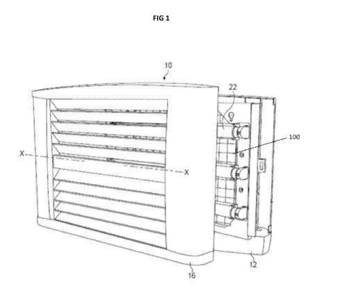
Fig 1 illustrates a typical prior art insect trap (10). It comprises a number
of basic
components: a back housing (12), a light source in the form of fluorescent, UV
emitting tubes (22), an insect capture means (100) and a cover (16). The
figure
shows the fluorescent tubes carried on a frame hinged to the back housing. The
plane of the back housing, and insect capture means, runs in the direction X-
X.
In contrast, and as illustrated in Figs 2, 3 and 4 (lower), the insect trap of
the
invention (10) comprises a cover (16) which hides the LEDs from view. All that
can be seen through the cover openings (18) (when the lights are off) are a
minor
portion of the glue board (100), a minor portion of the mount (14) supporting
the
LEDs, and a minor portion of the reflectors (44).
Referring to Fig 3 the mount (14) projects from, and is mounted to, the back
housing (12) and comprises two pairs of facing LED carrying members (24a; 24b)
which are inset from, a perimeter (20) of the back housing. Such a
configuration
has been shown by experiment (see below) to significantly improve insect
capture.
This or, for example, a substantially circular configuration orientates the
LEDs in
facing relationship to direct light to the centre (26) of the trap.
A further and significant feature in maximising capture efficiency is to
shield the
LEDs so the light is directed in a plane (X-X) parallel to the back housing
(12).
This may be achieved by housing the LEDs in e.g. a substantially U-shaped LED
carrying member(s) (24) (the LEDs are not visible in the Fig) which preclude
light
from being directed immediately outwardly through the cover (16) or
immediately
inwardly onto the insect capture means (100).
6
CA 03080797 2020-04-20
WO 2019/082051 PCT/IB2018/058199
The cover (16) is made of a translucent material and has an innermost surface
which is shaped or roughened to maximise the transmission of UV light as set
out
in EP1457111. The openings (18) which allow insects to enter the trap are
shaped to prevent the lights (22) being visible when viewed substantially
perpendicularly to the normal plane (X-X) of the back housing (12). The
general
principle of maintaining a pleasant appearance of a trap is set out in
EP0947134.
The data supporting the claimed invention is set out in the Examples below:
EXAMPLES
Methodology
1. Test Procedure ¨ 1 hour Fly Catch tests (Single trap test)
1.1. Houseflies were reared using a standard rearing procedure. Three to four
day old, mixed sex flies were used in the experiments;
1.2.200x flies were used for each replicate;
1.3. Before commencing the test, the Fly Test Room was cleaned of any
residual flies from previous tests. Walls and floors were moped using a
mild detergent in water.
1.4. Test Room measures 6 metres (length) by 3 metres (width) by 3 metres
(height);
1.5. The test room contains 8x 40 Watt Fluorescent tubes evenly spaced and
mounted on the ceiling;
1.6. Each tube is 4m in length and is a 'Cool white' colour;
1.7. Ambient UVA and the visible light intensity of the rooms fluorescent
light
lamps were measured immediately before the release of flies into the
room;
1.8. Immediately after the commencement of each test ambient UVA and
visible light were measured at a fixed point, from the centre of the room.
The reading was taken with the sensor face parallel to the ceiling, at a
distance of 1.5 metres from the ground;
7
CA 03080797 2020-04-20
WO 2019/082051 PCT/IB2018/058199
1.9. Temperature was maintained at 25 3 C and temperature and relative
humidity was recorded immediately before the release of any flies into the
room;
1.10. Traps were placed at 1.8m from the floor to the underside of the
trap, centrally on either of the long walls;
1.11. Trap UV output was measured by calibrated UVA test equipment on
the centre UV face of the trap at a distance of 1 meter from the face.
1.12. Two Hundred (200x) mixed sex flies were transferred into the room,
at the end farthest from the door, in the corner farthest from the trap.
allowed to acclimatize for 30 minutes to the new room environment with
the traps switched OFF;
1.13. After 30 minutes of acclimatization, the traps were switched ON,
environmental parameters recorded, and the traps were allowed to
operate. The flies were then released and the numbers of flies trapped
was recorded every 30min for a total of 60minutes.
Results
The results from sequential tests are set out in the Tables below:
Test 1
40 LED array (comparing outwardly and inwardly facing LEDs)
Table 2
Design Ave Catch (60min)
LED Outwardly 44%
LED Inwardly 93%
Surprisingly this test suggested that, unlike with fluorescent tubes, it was
not
desirable to directly transmit the light outwardly, to obtain the most
efficient
capture.
Test 2
8
CA 03080797 2020-04-20
WO 2019/082051 PCT/IB2018/058199
28 LED array with directional testing and testing the effect of the
translucent
cover.
Table 3
Design Ave Catch (60min)
LED Inwardly (90 deg ¨ 50%
towards glue board)
LED Parallel (180 deg) 72%
LED Splayed (45 deg 80%
inward)
LED Splayed (45 deg 44%
inward) translucent cover
blackened
This test demonstrated that the translucent cover was, like with a traditional
fluorescent tube, still playing a significant effect in attracting insects,
and that the
"internal lighting" of the trap was of significance.
Test 3
30 LED array - Additional effect of directional control, using guides or
baffles, to
limit the direction of light transmission and further effect of translucent
cover.
Table 4
Design Ave Catch (60min)
LED Parallel (180 deg) 83%
plus directional guides
precluding light being
transmitted directly
outwardly
LED Parallel (180 deg) 40%
plus directional guides
but with
translucent cover
9
CA 03080797 2020-04-20
WO 2019/082051 PCT/IB2018/058199
blackened
The results showed that the use of guides to control the direction of emission
maximised catch and that the translucency of the cover was of significance.
.. Test 4
30 LED array - Comparative study between UV fluorescent trap and UV LED trap
of otherwise equivalent design.
Table 5 ¨ Cobra trap (3 x fluorescent tubes)
Time post insect Cobra trap (fluorescent)
Catch (Ave)
release (minutes) 1 2 3 4 5
Replicate
46 62 64 50 32
50.8
60 58 86 80 72 58
70.8
Table 6 ¨Cobra trap (30 LED (UV) array)
Time post insect Cobra trap (LED)
Catch (Ave)
release (minutes) 1 2 3 4 5
Replicate
59 30 53 53 55 52
54.4
60 88 83 82 84 80
83.4
15 The results show a statistically significant improvement in catch rate
over 60
minutes (20% improvement).
Table 7 (Statistical analysis on Table 5 data)
t-Test: Paired Two Sample for Means 60mins
CCT LCT
Mean 70.8
83.4
Variance 161.2
8.8
Observations 5 5
Pearson Correlation -
0.223025967
Hypothesized Mean Difference 0
CA 03080797 2020-04-20
WO 2019/082051 PCT/IB2018/058199
df 4
t Stat -2.061422972
P(T<=t) one-tail 0.054138833
A statistically significant p value of 0.05 confirms the greater capture
efficiency of
the LED trap over a conventional fluorescent tube trap after 60 minutes of
operation.
Finally, Fig 4 illustrates, photographically, the different appearance of the
two
traps - LED (lower) compared to fluorescent (upper).
11