Note: Descriptions are shown in the official language in which they were submitted.
DIFFUSER PIPE WITH EXIT FLARE
TECHNICAL FIELD
[0001] The present application relates generally to centrifugal compressors
for gas
turbine engines, and more particularly to diffuser pipes for such centrifugal
compressors.
BACKGROUND
[0002] Diffuser pipes are provided in certain gas turbine engines for
diffusing a flow of
high speed air received from an impeller of a centrifugal compressor and
directing the
flow to a downstream component, such as an annular chamber containing the
combustor. The diffuser pipes are typically circumferentially arranged at a
periphery of
the impeller, and are designed to transform kinetic energy of the flow into
pressure
energy. Diffuser pipes seek to provide a uniform exit flow with minimal
distortion, as it is
preferable for flame stability, low combustor loss, reduced hot spots etc.
[0003] The diffuser pipes increase in cross-sectional area over their length,
in order to
provide diffusion of the air exiting the impeller. As the area gradually
increases, and the
flow within the pipe reduces in velocity, separation of the flow begins to
occur within the
diffuser pipe. The effectiveness of the diffuser is related to its ability to
raise the static
pressure while limiting the total pressure loss due to the diffusion.
SUMMARY
[0004] There is provided a compressor diffuser for a gas turbine engine, the
compressor diffuser comprising: diffuser pipes having a tubular body defining
a pipe
center axis extending therethrough, the tubular body including a first portion
extending
in a generally radial direction from an inlet of the tubular body, a second
portion
extending in a generally axial direction and terminating at a pipe outlet, and
a bend
portion fluidly linking the first portion and the second portion, the tubular
body having a
length defined between the inlet and the pipe outlet, the tubular body having
cross-
sectional profiles defined in a plane normal to the pipe center axis, an area
of the cross-
sectional profile at the pipe outlet is at least 20% greater than an area of
the cross-
1
Date Recue/Date Received 2020-05-20
sectional profile at a point upstream from the pipe outlet a distance
corresponding to
10% of the length of the tubular body.
[0005] There is provided a diffuser pipe comprising a tubular body defining a
pipe
center axis extending therethrough, the tubular body including a first portion
extending
in a generally radial direction from an inlet of the tubular body, a second
portion
extending in a generally axial direction and terminating at a pipe outlet, and
a bend
portion fluidly linking the first portion and the second portion, the tubular
body having a
length defined between the inlet and the pipe outlet, the tubular body having
cross-
sectional profiles defined in a plane normal to the pipe center axis, an area
of the cross-
sectional profile at the pipe outlet is at least 20% greater than the area of
the cross-
sectional profile at a last 10% of the length of the tubular body.
[0006] There is provided a method of increasing a static pressure of fluid
exiting a
centrifugal compressor of a gas turbine engine, the method including:
conveying the
fluid through a diffuser pipe to rapidly diffuse the fluid through a last 10%
of a length of
the diffuser pipe over which a cross-sectional area of the diffuser pipe
increases by at
least 20%.
BRIEF DESCRIPTION OF THE DRAWINGS
[0007] Reference is now made to the accompanying figures in which:
[0008] Fig. 1 is a schematic cross-sectional view of a gas turbine engine;
[0009] Fig. 2 is a perspective view of an impeller and diffuser pipes of a
centrifugal
compressor of the gas turbine of Fig. 1;
[0010] Fig. 3 is a perspective view of one of the diffuser pipes of Fig. 2;
[0011] Fig. 4 is a graph plotting area at various locations along a length of
a diffuser
pipe, such as the one shown in Fig. 3;
[0012] Fig. 5 shows examples of flow stream lines through the diffuser pipe of
Fig. 3;
and
2
Date Recue/Date Received 2020-05-20
[0013] Fig. 6 is a graph plotting equivalent cone angle (ECA) at various
locations along
a length of a diffuser pipe, such as the one shown in Fig. 3.
DETAILED DESCRIPTION
[0014] Fig. 1 illustrates a gas turbine engine 10 of a type preferably
provided for use in
subsonic flight, generally comprising in serial flow communication along an
engine
center axis 11 a fan 12 through which ambient air is propelled, a compressor
section 14
for pressurizing the air, a combustor 16 in which the compressed air is mixed
with fuel
and ignited for generating an annular stream of hot combustion gases, and a
turbine
section 18 for extracting energy from the combustion gases. The compressor
section 14
may include a plurality of stators 13 and rotors 15 (only one stator 13 and
rotor 15 being
shown in FIG. 1), and it may include a centrifugal compressor 19.
[0015] The centrifugal compressor 19 of the compressor section 14 includes an
impeller 17 and a plurality of diffuser pipes 20, which are located downstream
of the
impeller 17 and circumferentially disposed about a periphery of a radial
outlet 17A of
the impeller 17. The diffuser pipes 20 convert high kinetic energy at the
impeller 17 exit
to static pressure by slowing down fluid flow exiting the impeller. The
diffuser pipes 20
may also redirect the air flow from a radial orientation to an axial
orientation (i.e. aligned
with the engine axis 11). In most cases, the Mach number of the flow entering
the
diffuser pipe 20 may be at or near sonic, while the Mach number exiting the
diffuser
pipe 20 may be less than 0.25 to enable stable air/fuel mixing, and light/re-
light in the
combustor 16.
[0016] Fig. 2 shows the impeller 17 and the plurality of diffuser pipes 20,
also referred
to as "fishtail diffuser pipes", of the centrifugal compressor 19. Each of the
diffuser pipes
20 includes a diverging (in a downstream direction) tubular body 22, formed,
in one
embodiment, of sheet metal. The enclosed tubular body 22 defines a flow
passage 29
(see Fig. 3) extending through the diffuser pipe 20 through which the
compressed fluid
flow is conveyed. The tubular body 22 includes a first portion 24 extending
generally
tangentially from the periphery and radial outlet 17A of the impeller 17. An
open end is
provided at an upstream end of the tubular body 22 and forms an inlet 23 (see
Fig. 3) of
the diffuser pipe 20. The first portion 24 is inclined at an angle 81 relative
to a radial
3
Date Recue/Date Received 2020-05-20
axis R extending from the engine axis 11. The angle 81 may be at least
partially
tangential, or even substantially tangentially, and may further correspond to
a direction
of fluid flow at the exit of the blades of the impeller 17, such as to
facilitate transition of
the flow from the impeller 17 to the diffuser pipes 20. The first portion 24
of the tubular
body 22 can alternatively extend more substantially along the radial axis R.
[0017] The tubular body 22 of the diffuser pipes 20 also includes a second
portion 26,
which is disposed generally axially and is connected to the first portion 24
by an out-of-
plane curved or bend portion 28. An open end at the downstream end of the
second
portion 26 forms a pipe outlet 25 (see Fig. 3) of the diffuser pipe 20.
Preferably, but not
necessarily, the first portion 24 and the second portion 26 of the diffuser
pipes 20 are
integrally formed together and extend substantially uninterrupted between each
other,
via the curved, bend portion 28.
[0018] The large radial velocity component of the flow exiting the impeller
17, and
therefore entering the first portion 24 of each of the diffuser pipes 20, may
be removed
by shaping the diffuser pipe 20 with the bend portion 28, such that the flow
is redirected
axially through the second portion 26 before exiting via the pipe outlet 25 to
the
combustor 16. It will thus be appreciated that the flow exiting the impeller
17 enters the
inlet 23 and the upstream first portion 24 and flows along a generally radial
first
direction. At the outlet of the first portion 24, the flow enters the bend
portion 28 which
functions to turn the flow from a substantially radial direction to a
substantially axial
direction. The bend portion 28 may form a 90 degree bend. At the outlet of the
bend
portion 28, the flow enters the downstream second portion 26 and flows along a
substantially axial second direction different from the generally radial first
direction. By
"generally radial", it is understood that the flow may have axial, radial,
and/or
circumferential velocity components, but that the axial and circumferential
velocity
components are much smaller in magnitude than the radial velocity component.
Similarly, by "generally axial", it is understood that the flow may have
axial, radial,
and/or circumferential velocity components, but that the radial and
circumferential
velocity components are much smaller in magnitude than the axial velocity
component.
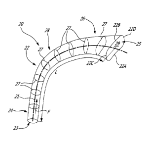
[0019] Referring now to Fig. 3, the tubular body 22 of each diffuser pipe 20
has a
radially inner wall 22A and a radially outer wall 22B. The tubular body 22
also has a first
4
Date Recue/Date Received 2020-05-20
side wall 22C spaced circumferentially apart across the flow passage 29 from a
second
side wall 22D. The radially inner and outer walls 22A,22B and the first and
second side
walls 22C,22D meet and are connected to form the enclosed flow passage 29
extending through the tubular body 22. The radially inner and outer walls
22A,22B and
the first and second side walls 22C,22D meet and are connected to form a
peripheral
edge of the tubular body 22 which circumscribes the pipe outlet 25. The
radially inner
wall 22A corresponds to the wall of the tubular body 22 that has the smallest
turning
radius at the bend portion 28, and the radially outer wall 22B corresponds to
the wall of
the tubular body 22 that has the largest turning radius at the bend portion
28.
[0020] The tubular body 22 diverges in the direction of fluid flow F
therethrough, in that
the internal flow passage 29 defined within the tubular body 22 increases in
cross-
sectional area between the inlet 23 and the pipe outlet 25 of the tubular body
22. The
increase in cross-sectional area of the flow passage 29 through each diffuser
pipe 20 is
gradual over some of diffuser pipe 20 and more abrupt in parts of the second
portion
26, as described in greater detail below. The direction of fluid flow F is
along a pipe
center axis 21 of the tubular body 22. The pipe center axis 21 extends through
each of
the first, second, and bend portions 24,26,28 and has the same orientation as
these
portions. The pipe center axis 21 is thus curved. In the depicted embodiment,
the pipe
center axis 21 is equidistantly spaced from the radially inner and outer walls
22A,22B of
the tubular body 22, and from the first and second side walls 22C,22D, through
the
tubular body 22.
[0021] Still referring to Fig. 3, the tubular body 22 has a length L defined
from the inlet
23 to the pipe outlet 25. The length L of the tubular body 22 may be measured
as
desired. For example, in Fig. 3, the length L is the length of the pipe center
axis 21 from
the inlet 23 to the pipe outlet 25. In an alternate embodiment, the length L
is measured
along one of the walls 22A,22B,22C,22D of the tubular body 22, from the inlet
23 to the
pipe outlet 25. Reference is made herein to positions on the tubular body 22
along its
length L. For example, a position on the tubular body 22 that is along a last
10% of the
length L is anywhere in the segment of the tubular body 22 that is upstream of
the pipe
outlet 25 a distance equal to 10% of the length L. This same segment is also
downstream of the inlet 23 a distance equal to 90% of the length L. Similarly,
a position
Date Recue/Date Received 2020-05-20
on the tubular body 22 that is along a first 90% of the length L is anywhere
in the
segment of the tubular body 22 that is downstream of the inlet 23 a distance
equal to
90% of the length L. This same segment is also upstream of the pipe outlet 25
a
distance equal to 10% of the length L.
[0022] The tubular body 22 is composed of many cross-sectional profiles 27
which are
arranged or stacked one against another along the length L of the tubular body
22.
Each cross-sectional profile 27 is a planar contour that lies in its own plane
that is
transverse or normal to the pipe center axis 21. Fig. 3 shows multiple cross-
sectional
profiles 27 in every portion 24,26,28 of the tubular body 22, and it will be
appreciated
that many more cross-sectional profiles 27 may be defined at other locations
along the
pipe center axis 21. In the depicted embodiment, the orientation of the cross-
sectional
profiles 27 in the frame of reference of the diffuser pipe 20 may vary over
the length L of
the tubular body 22, depending on where the cross-sectional profiles 27 are
located
along the pipe center axis 21. Each cross-sectional profile 27 defines the
shape,
contour, or outline of the tubular body 22 at a specific location along the
pipe center
axis 21.
[0023] Referring to Fig. 3, and as described in greater detail below, the
cross-sectional
profiles 27 vary over the length L of the tubular body 22. The cross-sectional
profiles 27
are different over the length L of the tubular body 22. Each cross-sectional
profile 27
may be unique, and thus different from the other cross-sectional profiles 27.
An area of
the cross-sectional profiles 27 varies along the length L of the tubular body
22. The
area of a given cross-sectional profile 27 is defined between the inner,
outer, first side,
and second side walls 22A,22B,22C,22D in the cross-sectional profile 27. The
area of
the cross-sectional profiles 27 increases over the length L of the tubular
body 22 in the
direction of the pipe outlet 25. This is consistent with the diverging flow
passage 29
defined by the tubular body 22.
[0024] Fig. 4 plots a normalized value for the area of the cross-sectional
profiles 27 of
the tubular body 22 at different points along the length L of the tubular body
22, where
the length L is provided as a normalized meanline length. The "meanline"
describes the
locus of points from the inlet 23 to the pipe outlet 25 where each point is
defined as the
center of each section. A final value for the cross-sectional area of the
tubular body 22
6
Date Recue/Date Received 2020-05-20
is defined at the pipe outlet 25, and is shown in Fig. 4 as corresponding to
100% of the
normalized value for the area of the cross-sectional profile 27 at the pipe
outlet 25. The
final value is the highest value for the cross-sectional area of the tubular
body 22. Fig. 4
shows the area curves for the tubular bodies 22 of diffuser pipes 20 with
different area
distributions along their lengths L. Referring to Figs. 3 and 4, the tubular
body 22 flares
outwardly adjacent to the pipe outlet 25. More particularly, the area of the
cross-
sectional profiles 27 in the last 10% of the length L of the tubular body 22
increases by
20% or more. In Fig. 4, this is shown as the area of the cross-sectional
profiles 27 going
from about 50% of the final value to 100% of the final value, over the last
10% of the
length L of the tubular body 22. The cross-sectional area of the diffuser pipe
20 thus
increases rapidly in the last section of the diffuser pipe 20, right before
the pipe outlet
25, thereby forming a diffuser pipe 20 which flares outwardly, like a trumpet,
at the end
portion thereof. The cross-sectional area of the diffuser pipe 20 does not
increase after
the pipe outlet 25, and achieves the final value at the pipe outlet 25. The
diffuser pipe
20 therefore ends or terminates at the pipe outlet 25.
[0025] Referring to Fig. 4, the area curve 30A for the tubular body 22 in Fig.
3 shows
that the area of the cross-sectional profile 27 at the pipe outlet 25 is more
than 20%
greater than the area of the cross-sectional profile 27 at a point or plane
where the last
10% of the length L of the tubular body 22 begins. Stated differently, an area
of the
cross-sectional profile at the pipe outlet is at least 20% greater than an
area of the
cross-sectional profile at a point upstream from the pipe outlet a distance
corresponding
to 10% of the length of the tubular body. The area curve 30A for the tubular
body 22 in
Fig. 3 shows that the area of the cross-sectional profile 27 at the pipe
outlet 25 is more
than 25% greater than the area of the cross-sectional profile 27 at the
beginning of the
last 10% of the length L of the tubular body 22. In Fig. 4, this is shown as
the area of
the cross-sectional profiles 27 for the area curve 30A going from about 50% of
the final
value to 100% of the final value, over the last 10% of the length L of the
tubular body
22. Thus, for the area curve 30A, the cross-sectional profiles 27 increase in
area by
50% or more over the last 10% of the length L. For the area curve 30A, the
area of the
cross-sectional profile 27 at the pipe outlet 25 is more than 50% greater than
the area
of the cross-sectional profile 27 immediately upstream of the last 10% of the
length L.
7
Date Recue/Date Received 2020-05-20
Thus the area of the cross-sectional profiles 27 in the last 10% of the length
L of the
area curve 30A increases by more than 25%, or by at least 25%.
[0026] For the area curve 30A, the cross-sectional profiles 27 increase in
area by at
least 40% over the last 20% of the length L of the tubular body 22. In Fig. 4,
this is
shown as the area of the cross-sectional profiles 27 for the area curve 30A
going from
about 40% of the final value to 100% of the final value, over the last 20% of
the length L
of the tubular body 22. More particularly, the area of the cross-sectional
profile 27 at the
pipe outlet 25 in the area curve 30A is about 60% greater than the area of the
cross-
sectional profile 27 at the last 20% of the length L. The diffuser pipe 20
having the area
curve 30A thereby undergoes an area change of at least 60% in the last 20% of
the
length L of the diffuser pipe 20. Indeed, and as shown in Fig. 4, the cross-
sectional
profiles 27 of the area curve 30A increase in area by more than 50% over the
last 20%
of the length L.
[0027] For the area curve 30A, the cross-sectional profiles 27 increase in
area by at
least 50% over the last 30% of the length L of the tubular body 22. For the
area curve
30A, the cross-sectional profiles 27 increase in area by at least 50% over the
last 25%
of the length L of the tubular body 22. In Fig. 4, this is shown as the area
of the cross-
sectional profiles 27 for the area curve 30A going from about 33% of the final
value to
100% of the final value, over the last 30% of the length L of the tubular body
22. The
diffuser pipe 20 having the area curve 30A thereby undergoes an area change of
at
least 50% in the last 25% of the length L of the diffuser pipe 20.
[0028] The area curve 30A shows that the diffuser pipe 20 may undergo
increases in
the area of its cross-sectional profiles 27 of 50% or more in the last 10% of
the length L
of the diffuser pipe 20, in the last 20% of the length L of the diffuser pipe
20, and/or in
the last 25% of the length L of the diffuser pipe 20.
[0029] Referring to Fig. 4, another possible area curve 30B for the tubular
body 22 in
Fig. 3 shows that the area of the cross-sectional profile 27 at the pipe
outlet 25 is 20%
greater than the area of the cross-sectional profile 27 at the last 10% of the
length L of
the tubular body 22. Thus the area of the cross-sectional profiles 27 in the
last 10% of
the length L of the area curve 30B increases by 20%. In Fig. 4, this is shown
as the
8
Date Recue/Date Received 2020-05-20
area of the cross-sectional profiles 27 for the area curve 30B going from
about 80% of
the final value to 100% of the final value, over the last 10% of the length L
of the tubular
body 22. Another possible area curve 30C for the tubular body 22 in Fig. 3
shows that
the area of the cross-sectional profile 27 at the pipe outlet 25 is 33%
greater than the
area of the cross-sectional profile 27 at the last 20% of the length L of the
tubular body
22. In Fig. 4, this is shown as the area of the cross-sectional profiles 27
for the area
curve 30C going from about 66% of the final value to 100% of the final value,
over the
last 20% of the length L of the tubular body 22. The area curve 30D shows that
the area
of the cross-sectional profile 27 at the pipe outlet 25 is 33% greater than
the area of the
cross-sectional profile 27 at the last 30% of the length L of the tubular body
22. In Fig.
4, this is shown as the area of the cross-sectional profiles 27 for the area
curve 30D
going from about 66% of the final value to 100% of the final value, over the
last 30% of
the length L of the tubular body 22.
[0030] The increase in cross-sectional area of the diffuser pipe 20 over a
short distance
of the diffuser pipe 20 may allow for rapid diffusion at the exit of the
diffuser pipe 20.
This may lead to increased static pressure prior to providing the fluid flow F
downstream into a plenum and ultimately into the combustion chamber of the
combustor 16. Since diffusion occurs rapidly and over a short distance at the
exit of the
diffuser pipe 20, there may be lower pressure loss when compared to a
conventional
diffuser pipe where diffusion occurs over a more gradual increase in cross-
sectional
area. Thus the distribution of the cross-sectional area toward the exit of the
diffuser pipe
20 may result in higher static pressure recovery and lower loss. The area
curve 30E for
such a conventional diffuser pipe, where diffusion occurs over a more gradual
increase
in cross-sectional area, is shown in Fig. 4. As can be seen, the cross-
sectional area in
the area curve 30E increases in a substantially linear manner over the length
of the
conventional diffuser pipe.
[0031] Still referring to Fig. 4, an upstream area of the diffuser pipe 20 has
a more
gradual increase in the area of the cross-sectional profiles 27. Referring to
the area
curves 30A,30B,30C, the cross-sectional profiles 27 increase linearly in area
over an
upstream segment of the tubular body 22 starting at 0% of the length L of the
tubular
body (i.e. at the inlet 23) and terminating at approximately 80% of the length
L. The
9
Date Recue/Date Received 2020-05-20
slope of the area curves 30A,30B,30C is substantially constant over the
upstream
segment. Thus, the tubular body 22 represented by the area curves 30A,30B,30C
increase gradually in cross-sectional area over the upstream segment. Stated
differently, the increase in area of the diffuser pipe 20 represented by the
area curves
30A,30B,30C is much greater near the exit of the diffuser pipe 20 than further
upstream
within the diffuser pipe 20. Thus, diffusion occurs through a majority of the
pipe length,
and more diffusion occurs near the exit of the diffuser pipe 20. The upstream
segment
of the diffuser pipe 20 may also have other shapes and profiles.
[0032] As seen in Fig. 4, all of the area curves 30A,30B,30C,30D, including
the area
curve 30E for the conventional diffuser pipe, have the same value for the area
of their
respective cross-sectional profiles 27 at the pipe outlet 25. In an
embodiment, the
radius of the diffuser pipe 20, its length L along the pipe center axis 21,
and its overall
area ratio are the same as that of the conventional diffuser pipe. The primary
difference
is that the diffuser pipe 20 performs less diffusion through a majority of the
pipe length
and more diffuser near the exit, compared to the conventional diffuser pipe.
[0033] Fig. 5 shows possible lines of the fluid flow F through the diffuser
pipe 20. As
can be seen, the fluid flow F may remain clean and oriented parallel to the
pipe center
axis 21 through most of the diffuser pipe 20. The fluid flow F may be cleaner
throughout
upstream sections of the diffuser pipe 20 because of less diffusion, and there
may be a
reduction in separated fluid flow F near the exit. The exit flare of the
diffuser pipe 20
may help to lower the average exit Mach number, may help to increases Cp
(static
pressure recovery), and/or may help to lower the omega (w) loss.
[0034] Fig. 6 shows equivalent cone angle (ECA) plotted along the length L of
the
tubular body 22, where the length L is provided as a normalized meanline
length. A
larger ECA value is generally an indication of more diffusion and potentially
more
pressure loss. A lower ECA value is preferable when the flow path of the
diffuser pipe
20 is turning (i.e. in the bend portion). A higher ECA value after the turning
can indicate
that flow is diffusing more efficiently. It can be seen that the diffuser pipe
20 has a lower
ECA through most of the length L of the diffuser pipe 20 when compared to a
conventional diffuser pipe, which contributes to lower diffusion and loss in
the bend
Date Recue/Date Received 2020-05-20
portion 28 of the diffuser pipe 20. Static pressure recovery (Cp), losses (w)
and the
ECA are determined according to the following formulae:
A, Ai
cP = = Ps,out42t¨P5.inist Pt.mist¨Ftxnalet
ECA = 2 X tan -1 _____________________________________________
Pt.tniet¨PLiNiet PrAnet--Ps.,intert
[0035] Where Ps is the static pressure, Pt is the total pressure (Ps +
pressure from
kinetic energy), Al is the cross-sectional area of diffuser pipe 20 at the
inlet 23, A2 is
the cross-sectional area of diffuser pipe 20 at the pipe outlet 25, and L is
the meanline
length of the diffuser pipe 20.
[0036] Referring to Figs. 3 and 4, there is also disclosed a method of
increasing static
pressure of fluid at the combustor 16. The method includes conveying the fluid
through
the diffuser pipe 20 to rapidly diffuse the fluid through a last 10% of the
length L, over
which a cross-sectional area of the diffuser pipe 20 increases by at least
20%.
[0037] The above description is meant to be exemplary only, and one skilled in
the art
will recognize that changes may be made to the embodiments described without
departing from the scope of the invention disclosed. Still other modifications
which fall
within the scope of the present invention will be apparent to those skilled in
the art, in
light of a review of this disclosure, and such modifications are intended to
fall within the
appended claims.
11
Date Recue/Date Received 2020-05-20