Note: Descriptions are shown in the official language in which they were submitted.
1
CHILLER WATER SAMPLING DEVICE
Cross-Reference to Related Application
The present application claims the priority of U.S. Provisional Application
Number 62/585,639, filed November 14, 2017.
BACKGROUND OF THE INVENTION
1. Field of the Invention
The present invention relates to devices for monitoring the level of biocide
in
poultry plant chillers.
2. Brief Description of the Prior Art
Peroxyacetic acid is employed in food chillers, such as auger and drag type
poultry chillers, which are employed in processing plants to reduce the
temperature of
birds which have been defeathered, eviscerated and are otherwise ready for
packaging.
Poultry chillers are described, for example, in U.S. Patents 3,240,026;
7,281,384;
6,865,895; 9,271,509. Various
methods have been
employed to reduce microbial activity in chiller water, which is typically
recirculated and
cooled during recirculation. For example, U.S. Patent 4,849,237 discloses
sanitizing
poultry carcasses using ozonated water at low temperatures. U.S. Patent
Publication
2009/0208616 Al discloses a multistage process for treating poultry processing
water
with chlorine and ozone. Peroxycarboxylic acids have been used to reduce
microbial
activity in poultry processing. For example, U.S. Patent 5,683,724 describes a
process
for inhibiting microbial growth in aqueous food process streams using a
percarboxylated
acid, such as peracetic add. U.S. Patent 9,414,609 discloses treating poultry
carcasses
with an equilibrium solution of peroxyacetic acid at an elevated tern perature
prior to
chilling. Peroxyacetic acid can be provided in the form of an equilibrium
solution, or a
non-equilibrium solution, such as disclosed, for example, in U.S. Patent
10,081,784.
When peroxyacetic acid is used as an antimicrobial agent in poultry chillers,
there is a need to accurately assess the level of peroxyacetic acid to ensure
efficacious
results.
SUMMARY OF THE INVENTION
The present invention relates to a chiller water sampling device. The device
includes a first line for fluid communication with a chiller, such that an
aqueous sample
can be delivered from the chiller to the device. The device also includes a
first flow
meter for sensing fluid flow through the first line; a diverter in fluid
communication with
the first line for dividing the fluid flow from the first line into a second
line and a third line;
a second flow meter for sensing fluid flow through the second line; and a
first valve for
Date Recue/Date Received 2023-03-30
CA 03081360 2020-04-30
WO 2019/099434
PCT/US2018/060889
2
controlling fluid flow through the second line such that fluid flow from the
device can be
discharged through the second line.
The device also includes a second valve for controlling fluid flow through the
third line and a mixing tank for receiving fluid flow from the third line, as
well as an acid
storage tank in fluid communication with the mixing tank, and a first metering
device for
controlling fluid flow from the acid storage tank to the mixing tank. A first
pH sensing
device for monitoring the pH of fluid in the mixing tank is also provided. The
pH first
sensing device generates a first signal responsive to the pH of the fluid in
the mixing
tank, the first signal being applied to the first metering device for
controlling fluid flow
from the acid storage tank to the mixing tank. A fourth line for discharging
fluid from the
mixing tank is also provided.
Further, a second pH sensing device for monitoring the pH of fluid flowing in
the
fourth line is provided, as well as a fifth line in fluid communication with
the fourth line for
discharging fluid from the device, and a third valve for controlling fluid
flow through the
fourth line. A sixth line in fluid communication with the fourth line for
discharging fluid
from the device is also provided, as well as a fourth valve for controlling
fluid flow
through the sixth line. The second pH sensing device generates a second signal
for
controlling operation of the fourth valve and a third signal for controlling
operation of the
fourth valve.
In addition, a first PAA sensing device for sensing the concentration of
peroxyacetic acid in fluid flowing in the sixth line is provided, the first
PAA sensing
device has an operating range, and provides a signal in response to the
concentration
of sensed concentration of peroxyacetic acid signal.
Preferably, the device further comprises a filter in the third line for
filtering non-
fluid material from fluid flowing from the diverter to the second valve.
Preferably, the device further includes a seventh line for providing fluid
flow to
the third line, fluid flow through the seventh line being controlled by a
fifth valve, the
seventh line being in fluid communication with the third line between the
diverter and the
second valve.
Preferably, the device also includes an overflow line, the overflow line being
in
fluid communication with the mixing tank for discharging fluid from the
device, the
overflow line being positioned on the mixing tank above a predetermined fluid
level in
the mixing tank.
Preferably, the device also includes a second PAA sensing device for sensing
the concentration of peroxyacetic acid in the sixth line.
Preferably, the device further includes an eighth line for providing fluid
flow to the
sixth line, the fluid flow in the eighth line being controlled by a sixth
valve, the eighth line
CA 03081360 2020-04-30
WO 2019/099434
PCT/US2018/060889
3
being in fluid communication with the sixth line between the fourth valve and
the first
PAA sensing device. Wash water can be provided through the eighth line.
Preferably, the first flow meter generates a first flow control signal, the
second
flow meter generates a second flow control signal, and the first valve is a
proportional
valve. Preferably, the device further includes a controller for comparing the
first signal
and the second signal, and for generating a control signal for the
proportional valve,
such that the flow through the third line is maintained at a predetermined
flow rate.
The present invention also provides a system for controlling the concentration
of
peroxyacetic acid in the contents of a chiller, the system comprising the
chiller water
sampling device, a source of peroxyacetic acid, a metering pump for delivering
peroxyacetic acid to the chiller, and a controller for the metering pump, the
controller for
the metering pump being controlled by a signal from the first PAA sensing
device.
Preferably, the system further comprises a unit for controlling the pH of the
contents of the chiller, the unit comprising a delivery line in fluid
communication with the
chiller, a pH sensing device for sensing the pH of fluid in the delivery line,
and a flow
meter for sensing the rate of flow of fluid in the delivery line.
Preferably, in the system fluid output from the delivery line is input to the
first line
of the device.
Preferably, the system further comprises an alkali storage tank for storing an
alkaline fluid, an alkali controller, and an alkali feed pump for delivering
the alkaline fluid
to the chiller, the alkali controller receiving a signal from the pH sensing
device and
activating the alkali feed pump when the signal from the pH sensing device
meets a
predetermined condition.
In one embodiment of the system of the present invention, the source of
peroxyacetic acid provides equilibrium peroxyacetic acid. In another
embodiment, the
source of peroxyacetic acid provides nonequilibrium peroxcyacetic acid.
The present invention also provides a process for controlling the
concentration of
peroxyacetic acid in a chiller employing the chiller water sampling device.
The process
includes providing a continuous sample of aqueous alkaline fluid from a
chiller to the
first line, controlling the first valve to provide a predetermined constant
flow rate of the
sample to the mixing tank, mixing the aqueous fluid provided to the mixing
tank,
monitoring the pH of the aqueous fluid in the mixing tank, and adding.acid to
the
aqueous fluid in the mixing tank to reduce the pH of the aqueous fluid in the
mixing tank,
monitoring the pH of the aqueous fluid in the fourth line, delivering aqueous
fluid in the
fourth line to the sixth line when the monitored pH of the aqueous fluid in
the fourth line
is within the working range of the first PAA sensing device; and delivering
peroxyacetic
acid to the chiller in response to the signal from the third sensing device.
CA 03081360 2020-04-30
WO 2019/099434
PCT/US2018/060889
4
Preferably, the process further includes providing a second PAA sensing device
for sensing the concentration of peroxyacetic acid in the sixth line, the
second sensing
device providing a second signal in response to the concentration of sensed
concentration of peroxyacetic acid signal, and comparing the signals of the
first and
second PAA sensing devices.
BRIEF DESCRIPTION OF THE DRAWINGS
Fig. 1 is a schematic illustration of a chiller water sampling device
according to
the present invention.
Fig. 2 is a schematic illustration of a system for controlling the
concentration of
peroxyacetic acid in the contents of a chiller employing the device of Fig. 1.
DETAILED DESCRIPTION
The present invention provides a chiller water sampling device for assessing
the
level of peroxyacetic acid in the water of a poultry chiller, and a system
employing the
device for controlling the concentration of peroxyacetic acid in the chiller
water, as well
as a method for controlling the concentration of peroxyacetic acid in the
chiller water.
As used in this specification and claims, "PAA" means peroxyacetic acid (also
referred to a "peracetic acid).
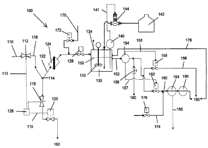
Referring to Figs. 1 and 2, wherein like reference numerals refer to like
elements
throughout the several views, the chiller water sampling device 100 of the
present
invention includes a first line 110 for fluid communication with a chiller 300
(Fig. 2). A
stream of chiller water initially flows through a first flow meter 112 for
sensing fluid flow
through the first line 110. The first flow meter 112 generates a responsive
signal over a
first flow control line 113. At the end of the first line 110 a diverter 114
such as a "Y"-
fitting, and in fluid communication with the first line 110, is provided to
split the stream of
chiller water into two streams, one of which flows into a second line 116, and
a third line
122. Preferably, the "Y"-fitting permits large contaminant particles in the
chller water to
flow downwards through the second line 116. There are fluctuations in the
fluid flow
through the first line 110, and it is desirable to provide a uniform flow rate
in which the
concentration of peroxyacetic acid can be sampled, the fluid flowing in the
second line
116 passes though a second flow meter for sensing the fluid flow through the
second
line 116, then though a first, proportional valve 120 for controlling the
fluid flow in the
second line, and subsequently to a drain 180 for discharging fluid flow from
the device
100. A signal provided over the first flow control me from the first flow
meter 112 and a
signal provided over a second flow control line 115 from the second flow meter
118 are
compared by a flow controller 126, which is programmed to adjust the first
valve 120
such that the fluid flow though the third line 122 is maintained at a
predetermined rate,
such as, for example, 0.3 gal./min (1.14 liters/minute). Fluid flowing in the
third line then
CA 03081360 2020-04-30
WO 2019/099434
PCT/US2018/060889
preferably passes through a filter 124 such as a mesh screen to strain out
residual large
particles. The fluid flowing in the third line 122 then passes though a second
valve 128
for controlling fluid flow in the third line 122 for a purpose to be described
below.
The chiller water flowing in the third line 122 discharges to a mixing tank
130 for
5 receiving fluid flow from the third line 122 for the purpose of adjusting
the pH of the
chiller water if necessary in order that the concentration of peroxyacetic
acid be
accurately assessed. The mixing tank 130 is provided with a mixer or stirrer
132 as well
as a vent 134.
The chiller water including the peroxyacetic acid can have a pH on the
alkaline
side. However, sensors for peroxyacetic acid typically have a limited pH
operating
range, such as from about 1 to 9. Thus, if the chiller water is more alkaline
than the
operating range of the PAA sensor being employed, the PAA measurement drops to
zero.
Thus, a first sensing device 140 for monitoring the pH of fluid in the mixing
tank
130 is provided. The first sensing device 140 generates a signal responsive to
the pH
of the fluid in the mixing tank 130. The signal is applied through a first pH
control line
141 to a first metering device or pump 144. An acid storage tank 142 is
provided in fluid
communication with the mixing tank 130 through the first metering device 144,
which
controls fluid flow from the acid storage tank 142 to the mixing tank 130. The
first
metering device 144 feeds acid from the acid storage tank 142 when the pH of
the
contents of the mixing tank 130 rise above a predeterimed level, such as a pH
of 8, for
the purpose of lowering the pH of the contents to a level within the working
range of the
PAA sensor to be employed. The fluid in the mixing tank 130 is preferably
maintained
at a constant level 150. Should that level be exceeded, an overflow line 176
is provided
for discharging the overflow from the mixing tank 130 to a drain 180.
A fourth line 152 is provided for discharging fluid from the mixing tank 130.
A
second pH sensing device 154 monitors the pH of fluid flowing in the fourth
line 152. If
the pH of the fluid in the fourth line 152 exceeds a predetermined pH, such as
a pH of 8,
the second pH sensing device 154 generates signals which are transmitted over
a
second pH control line 155 and a third pH control line 157, such that the
fluid is
discharged through a fifth line 156 in fluid communication with the fourth
line 152 and a
third valve 158 for controlling fluid flow through the fifth line 156 to
discharge fluid from
the mixing tank 130 to a drain 180. In addition, a sixth line 160 in fluid
communication
with the fourth line 152 is also provided, as well as a fourth valve 162 for
controlling fluid
flow through the sixth line 160.
Depending on the sensed pH, the second sensing device 154 generates a signal
which is applied over the second pH control line 155 for controlling operation
of the third
CA 03081360 2020-04-30
WO 2019/099434
PCT/US2018/060889
6
valve 158 and a signal applied over the third pH control line 157 for
controlling operation
of the fourth valve 162. If the pH is above a predetermined value, the third
valve 158 is
opened and the fourth valve 162 is closed so that the chiller water is
discharged to the
drain 180. If the pH is below a predetermined value, the third valve 158 is
closed, and
the fourth valve 162 is opened to permit the chiller water to flow through the
sixth line
160.
A first PAA sensing device 164 is provided, and preferably a second PPA
sensing device 190, for sensing the concentration of peroxyacetic acid in
fluid flowing in
the sixth line 160. The first PAA sensing device 164 has a predetermined
operating
range, and provides a PAA concentration signal in response to the
concentration of
sensed concentration of peroxyacetic acid over a PAA signal line 165. The PAA
concentration signal is employed to adjust the concentration of PAA in the
chiller 300
as described below. Preferably, signals from the two PAA sensors 164, 190 are
compared, and if the two signals differ by more than a predetermined amount,
indicating
malfunction, one or both PAA can be replaced.
Preferably, the device 100 further includes a seventh line 170 for providing
fluid
flow, such as cleaning water, to the third line 122. The fluid flow through
the seventh
line is controlled by a fifth valve 172. The seventh line 170 is in fluid
communication
with the third line 122 between the diverter 114 and the second valve 128. In
order to
clean the filter 124, fluid flow from the chiller 300 is stopped, the second
valve 128 is
closed, and the first valve 120 is opened so that cleaning water can flow
through the
filter 124 and out the second line 116 to the drain 180. Further, if desired,
the second
valve 128 can be opened so that cleaning water can flow through the mixing
tank 130
and then to the fourth line 152. A fifth line 156 is provided in fluid
communication with
the fourth line 152, with flow through the fifth line 156 being controled by a
seventh
valve 168. If the third valve 158 and the fourth valve 162 are closed, and the
seventh
valve 168 is opened, cleaning water can flow from the fourth line 152 and can
flow out
the fifth line 156 to be discharged from the device 100 to a drain 180.
Similarly, an
eighth line 174 in fluid communication with the sixth line 160 between the
fourth valve
162 and the first PAA sensor 164 is provided. The eighth line 174 is
controlled by a
= sixth valve 178. In order to clean the PAA sensors 164, 190 in the sixth
line 160, the
fourth valve 162 can be closed, and the sixth valve 178 can be opened in order
to
permit cleaning water to flow through the eighth line 174, the sixth line 160
and the PAA
sensors 164, 190.
The present invention also provides a system for controlling the concentration
of
peroxyacetic acid in the contents of a chiller 300. The system includes the
device 100,
a PAA control system 400 which includes a PAA controller 410 a source of
peroxyacetic
CA 03081360 2020-04-30
WO 2019/099434
PCT/US2018/060889
7
acid, such as a PAA storage tank 402 containing an equilibrium solution of
PAA, a first
PAA delivery line 404 for fluid communication between the tank 402, and a PAA
metering pump 406 for delivering peroxyacetic acid to the chiller 300 through
a second
PAA delivery line 408, and a controller 410 for the metering pump. The
controller for the
metering pump is preferably controlled by a signal from the first PAA sensing
device
164.
The system of the present invention also provides a unit 200 for controling
the
pH of the contents of the chiller 300. The unit 200 includes a pH sample
delivery line
206 in fluid communication with the chiller for delivering a sample of the
chiller contents
to a pH control sensing device 208 for sensing the pH of fluid in the delivery
line 206,
and a pH sample flow meter 210 for sensing the rate of flow of fluid in the
delivery line
206. Preferably, the fluid output from a pH sample discharge line 212 is input
to the first
line 110 of the device 100 of the present invention. An alkali storage tank
222 is
employed for storing an alkaline fluid. The alkaline fluid, such as an aqueous
solution of
sodium hydroxide, is transferred to an alkali feed or metering pump 226 over a
first
alkali delivery line 224. An alkali pump controller 230 controls the operation
of the alkali
metering pump 226 for delivering the alkaline fluid over to the chiller 300
over a second
alkali delivery line 228. The alkali controller 230 receives a signal from the
pH control
unit device 200 and activating the alkali feed pump 230 when the signal from
the pH
control unit 200 meets a predetermined condition, such as when the pH of the
chiller
contents drops below a predetermined level.
The source of peroxyacetic acid can provide an equilibrium solution of
peroxyacetic acid. Equilibrium solutions of peroxyacetic acid can be prepared
remotely
from the processing plant employing the chiller, and stored until needed.
Conversely,
the source of peroxyacetic acid can be a device which generated peroxyacetic
acid in
situ and provides nonequilibrium peroxcyacetic acid.
The chiller water sampling device 100 is employed to control the concentration
of peroxyacetic acid in a chiller 300. A continuous sample of aqueous alkaline
fluid from
the chiller 300 is provided to the first line 110 of the device 100. For
example, the
sample can be delivered by the pH sample discharge line 212 of the pH control
unit 200.
The first valve 120 is controlled to provide a predetermined constant flow
rate of the
sample to the mixing tank 130, such as 0.3 gallons/minute (1.14
liters/minute). The
aqueous fluid in the mixing tank 130 is mixed, preferably continuously using a
mechanical stirring device or mixer 132. The pH of the aqueous fluid in the
mixing tank
130 is monitored with the first sensing device 140, and if the pH of the
aqueous fluid
exceeds a predetermined value, the acid addition flow controller 126 causes
acid stored
in the acid storage tank 142 to be added by the first metering device 144 to
the aqueous
CA 03081360 2020-04-30
WO 2019/099434
PCT/US2018/060889
8
fluid in the mixing tank 130 to reduce the pH of the aqueous fluid in the
mixing tank 130.
Since peroxyacetic acid sensors have a limited range of pH in which they can
operate
accurately, and because the pH of aqueous fluid in the chiller may exceed the
operating
range of the peroxyacetic acid sensor, the pH of a sample of aqueous fluid
from the
chiller 300 must be reduced to within the operating range of the peroxyacetic
acid
sensor in order to accurately assess the level of peroxyacetic acid in the
chiller 300. In
order to protect the peroxyacetic acid devices 164, 190, the pH of the aqueous
fluid
leaving the mixing tank 130 in the fourth line 152 is monitored by the second
sensing
device 154. If the pH of the sample has been sufficiently reduced, the third
valve 158 is
closed and the fourth valve 162 is opened, and the aqueous fluid sample in the
fourth
line 152 is delivered to the sixth line 160 when the monitored pH of the
aqueous fluid in
the fourth line is within the working range of the PAA sensing devices 164,
190. The
measured level of peroxyaceticacid acid in the sample is then used to control
the
addtion of peroxyacetic acid to the chiller 300. A PAA control signal is
generated by the
PAA sensing device 164, and peroxyacetic acid is delivered to the chiller 300
in
response to the signal from the first PAA sensing device.
Preferably, the second PAA sensing device is provided for sensing the
concentration of peroxyacetic acid in the sixth line 160. The second PAA
sensing
device 190 provides a second signal in response to the concentration of sensed
concentration of peroxyacetic acid signal. The signals from the first PAA
sensing device
164 and the second PAA sensing device 190 can be compared. If the PAA levels
measured by the two devices differ by greater than a predetermined amount,
indicating
a defective or damaged sensor, that sensor can be replaced.
Various modifications can be made in the details of the various embodiments of
the apparatus and method of the present invention, all within the scope and
spirit of the
invention as defined by the appended claims