Note: Descriptions are shown in the official language in which they were submitted.
86105153 CA 03081676 2020-05-04
1
Description
Title of Invention: METHOD OF TRANSMITTING AND
RECEIVING CHANNEL STATE INFORMATION IN WIRELESS
COMMUNICATION SYSTEM AND APPARATUS THEREFOR
Technical Field
[1] The present disclosure generally relates to a wireless communication
system and,
more particularly, to transmitting and receiving channel state information.
Background Art
[2] Mobile communication systems have been generally developed to provide
voice
services while guaranteeing user mobility. Such mobile communication systems
have
gradually expanded their coverage from voice services through data services up
to
high-speed data services. However, as current mobile communication systems
suffer
from resource shortages and increased user demand for even higher-speed
services, de-
velopment of more advanced mobile communication systems is needed.
[3] The requirements of the next-generation mobile communication system may
include
supporting increased data traffic, an increase in the transfer rate of each
user, the ac-
commodation of a significantly increased number of connection devices, very
low end-
to-end latency, and high energy efficiency. To this end, various techniques,
such as
small cell enhancement, dual connectivity, massive multiple input multiple
output
(MIMO), in-band full duplex, non-orthogonal multiple access (NOMA), supporting
super-wide band, and device networking, have been researched.
Disclosure of Invention
[4] Implementations of the present disclosure enable transmitting and
receiving channel
state information (CSI).
Date Recue/Date Received 2020-05-04
86105153
la
[51 According to an aspect of the present invention, there is provided a
method of
transmitting channel state information (CSI) related to beam reporting by a
terminal in a wireless communication system, the method comprising: receiving
downlink control information (DCI) that triggers a CSI reporting; receiving an
aperiodic CSI-reference signal (CSI-RS) for the CSI reporting; and
transmitting,
to a base station, a CSI report related to beam reporting that is determined
based
on the aperiodic CSI-RS, wherein based on the CSI reporting being configured
for Layer 1 reference signal received power, L 1-RSRP, reporting: the CSI
report
is transmitted at least a minimum required time after receiving the DCI,
wherein
the minimum required time for the L 1-RSRP reporting is configured based on
(i)
a first timing parameter related to a time duration between a last timing of
the
aperiodic CSI-RS and a transmission timing of the CSI report, and (ii) a
second
timing parameter related to a time duration between a timing of a DCI
triggering
the aperiodic CSI-RS and a timing of the aperiodic CSI-RS, and wherein the
method further comprises reporting, to the base station, capability
information
including first information regarding the first timing parameter and second
information regarding the second timing parameter, wherein the second
information indicates a minimum time duration between the timing of the DCI
triggering the aperiodic CSI-RS and the timing of the aperiodic CSI-RS, and
wherein the aperiodic CSI-RS is received at a timing equal to or greater than
the
minimum time duration after receiving the DCI.
[5a] According to another aspect of the present invention, there is
provided a terminal
configured to transmit channel state information (CSI) related to beam
reporting
in a wireless communication system, the terminal comprising: a radio frequency
(RF) unit; at least one processor; and at least one computer memory operably
connectable to the at least one processor and storing instructions that, when
executed by the at least one processor, perform operations comprising:
receiving
downlink control information (DCI) that triggers a CSI reporting; receiving an
aperiodic CSI-reference signal (CSI-RS) for the CSI reporting; and
transmitting,
to a base station through the RF unit, a CSI report related to beam reporting
that is
determined based on the aperiodic CSI-RS, wherein based on the CSI reporting
being configured for Layer 1 reference signal received power, L 1-RSRP,
Date Recue/Date Received 2021-10-05
86105153
lb
reporting: the CSI report is transmitted at least a minimum required time
after
receiving the DCI, wherein the minimum required time for the L 1-RSRP
reporting is configured based on (i) a first timing parameter related to a
time
duration between a last timing of the aperiodic CSI-RS and a transmission
timing
of the CSI report, and (ii) a second timing parameter related to a time
duration
between a timing of a DCI triggering the aperiodic CSI-RS and a timing of the
aperiodic CSI-RS, and wherein the operations further comprise reporting, to
the
base station, capability information including first information regarding the
first
timing parameter and second information regarding the second timing parameter,
wherein the second information indicates a minimum time duration between the
timing of the DCI triggering the aperiodic CSI-RS and the timing of the
aperiodic
CSI-RS, and wherein the aperiodic CSI-RS is received at a timing equal to or
greater than the minimum time duration after receiving the DCI.
[513] According to another aspect of the present invention, there is
provided a base
station configured to receive channel state information (CSI) related to beam
reporting in a wireless communication system, the base station comprising: a
radio frequency (RF) unit; at least one processor; and at least one computer
memory operably connectable to the at least one processor and storing
instructions that, when executed by the at least one processor, perform
operations
comprising: transmitting, to a terminal through the RF unit, downlink control
information (DCI) that triggers a CSI reporting; transmitting, to the terminal
through the RF unit, an aperiodic CSI-reference signal (CSI-RS) for the CSI
reporting; and receiving, from the terminal through the RF unit, a CSI report
related to beam reporting that is determined based on the aperiodic CSI-RS,
wherein based on the CSI reporting being configured for Layer 1 reference
signal
received power, L 1-RSRP, reporting: the CSI report is transmitted by the
terminal
at least a minimum required time after the terminal receives the DCI, wherein
the
minimum required time for the L 1-RSRP reporting is configured based on (i) a
first timing parameter related to a time duration between a last timing of the
aperiodic CSI-RS and a transmission timing of the CSI report, and (ii) a
second
timing parameter related to a time duration between a timing of a DCI
triggering
the aperiodic CSI-RS and a timing of the aperiodic CSI-RS, and wherein the
Date Recue/Date Received 2021-10-05
86105153
lc
operations further comprise receiving, from the terminal, capability
information
including first information regarding the first timing parameter and second
information regarding the second timing parameter, wherein the second
information indicates a minimum time duration between the timing of the DCI
triggering the aperiodic CSI-RS and the timing of the aperiodic CSI-RS, and
wherein the aperiodic CSI-RS is transmitted at a timing equal to or greater
than
the minimum time duration after transmitting the DCI.
[6] One general aspect of the present disclosure includes a method of
performing
channel state information (CSI) reporting by a terminal in a wireless
communication system, the method including: receiving downlink control
information (DCI) that triggers the CSI reporting. The method of performing
channel state information reporting also includes receiving a CSI-reference
signal
(CSI-RS) for the CSI reporting. The method of performing channel state
information reporting also includes transmitting, to a base station, CSI that
is
determined based on the CSI-RS that is received. The method of performing
channel state information reporting also includes where a minimum required
time
for the CSI reporting is configured based on (i) a first
Date Recue/Date Received 2021-10-05
86105153 CA 03081676 2020-05-04
2
minimum required time from a last timing of the CSI-RS to a transmission
timing of
the CSI reporting, and (ii) a second minimum required time between a DCI
triggering
the CSI-RS and a reception of the CSI-RS. Other embodiments of this aspect
include
corresponding computer systems, apparatus, and computer programs recorded on
one
or more computer storage devices, each configured to perform the actions of
the
methods.
[6a] Implementations may include one or more of the following features. The
method
where reporting information for the CSI reporting includes any one of (i) a
CSI-RS
resource indicator (cri) and a reference signal received power (RSRP), (ii) a
synchro-
nization signal block (SSB) identifier and the RSRP, or (iii) no report. The
method
where the minimum required time for the CSI reporting is configured as a sum
of (i)
the first minimum required time from the last timing of the CSI-RS to the
transmission
timing of the CSI reporting, and (ii) the second minimum required time between
a DCI
triggering the CSI-RS and a reception of the CSI-RS. The method where
information
for the first minimum required time is reported, by the terminal, to the base
station as
ue capability information. The method where the CSI-RS is configured to be
aperi-
odically transmitted. The method may also include where the DCI that schedules
the
CSI-RS is triggering DCI for the CSI-RS. The method where information for the
second minimum required time is reported, by the terminal, to the base station
as ue
capability information. The method where a number of processing units that are
utilized by the terminal to perform the CSI reporting is equal to 1.
Implementations of
the described techniques may include hardware, a method or process, or
computer
software on a computer-accessible medium.
[71 Another general aspect of the present disclosure includes a terminal
configured to
perform channel state information (CSI) reporting in a wireless communication
system, the terminal including: a radio frequency (RF) unit. The terminal also
includes
at least one processor; and at least one computer memory operably connectable
to the
at least one processor and storing instructions that, when executed by the at
least one
processor, perform operations including: receiving, through the RF unit,
downlink
control information (DCI) that triggers the CSI reporting. The operations also
include
receiving, through the RF unit, a CSI-reference signal (CSI-RS) for the CSI
reporting.
The operations also include transmitting, to a base station through the RF
unit, CSI that
is determined based on the CSI-RS that is received. A minimum required time
for the
CSI reporting is configured based on (i) a first minimum required time from a
last
timing of the CSI-RS to a transmission timing of the CSI reporting, and (ii) a
second
minimum required time between a DCI triggering the CSI-RS and a reception of
the
CSI-RS. Other embodiments of this aspect include corresponding computer
systems,
apparatus, and computer programs recorded on one or more computer storage
devices,
Date Recue/Date Received 2020-05-04
CA 03081676 2020-05-04
WO 2020/032432 PCT/KR2019/009127
3
each configured to perform the actions of the methods.
[8] Implementations may include one or more of the following features. The
terminal
where reporting information for the CSI reporting includes any one of (i) a
CSI-RS
resource indicator (cri) and a reference signal received power (RSRP), (ii) a
synchro-
nization signal block (SSB) identifier and the RSRP, or (iii) no report. The
terminal
where the minimum required time for the CSI reporting is configured as a sum
of (i)
the first minimum required time from the last timing of the CSI-RS to the
transmission
timing of the CSI reporting, and (ii) the second minimum required time between
a DCI
triggering the CSI-RS and a reception of the CSI-RS. The terminal where
information
for the first minimum required time is reported, by the terminal, to the base
station as
user equipment (UE) capability information. The terminal where the CSI-RS is
configured to be aperiodically transmitted. The terminal may also include
where the
DCI that schedules the CSI-RS is triggering DCI for the CSI-RS. The terminal
where
information for the second minimum required time is reported, by the terminal,
to the
base station as UE capability information. The terminal where a number of
processing
units that are utilized by the terminal to perform the CSI reporting is equal
to 1. Imple-
mentations of the described techniques may include hardware, a method or
process, or
computer software on a computer-accessible medium.
[91 Another general aspect of the present disclosure includes a base
station configured to
receive channel state information (CSI) in a wireless communication system,
the base
station including: a radio frequency (RF) unit. The base station also includes
at least
one processor; and at least one computer memory operably connectable to the at
least
one processor and storing instructions that, when executed by the at least one
processor, perform operations including: transmitting, through the RF unit,
downlink
control information (DCI) that triggers the CSI reporting. The operations also
include
transmitting, through the RF unit, a CSI-reference signal (CSI-RS) for the CSI
reporting. The operations also include receiving, from a terminal through the
RF unit,
CSI that is determined based on the CSI-RS that was transmitted. A minimum
required
time for the CSI reporting is configured based on (i) a first minimum required
time
from a last timing of the CSI-RS to a transmission timing of the CSI reporting
by the
terminal, and (ii) a second minimum required time between a DCI triggering the
CSI-
RS and a reception of the CSI-RS. Other embodiments of this aspect include
corre-
sponding computer systems, apparatus, and computer programs recorded on one or
more computer storage devices, each configured to perform the actions of the
methods.
[10] All or part of the features described throughout this disclosure can
be implemented as
a computer program product including instructions that are stored on one or
more non-
transitory machine-readable storage media, and that are executable on one or
more
processing devices. All or part of the features described throughout this
disclosure can
86105153 CA 03081676 2020-05-04
4
be implemented as an apparatus, method, or electronic system that can include
one or
more processing devices and memory to store executable instructions to
implement the
stated functions.
[11] The details of one or more implementations of the subject matter of
this disclosure
are set forth in the accompanying drawings and the description below. Other
features,
aspects, and advantages of the subject matter will become apparent from the de-
scription, the drawings, and the claims.
[12] According to some implementations of the present disclosure, there is
an effect in
that CSI calculation and CSI reporting can be efficiently performed when the
number
of processing units utilized by a terminal for CSI reporting is smaller than
the number
of CSI reportings that are configured and/or indicated by a base station in
CSI
reporting.
[13] Furthermore, according to some implementations of the present
disclosure, there is
an effect that an efficient Z value setting and efficient processing unit
utilization can be
realized in the case of L1-RSRP report used for beam management and/or beam
reporting use, in addition to normal CSI reporting.
[14] Effects which may be obtained by the present disclosure are not
limited to the above-
described effects, and various other effects may be evidently understood by
those
skilled in the art to which the present disclosure pertains from the following
de-
scription.
Brief Description of Drawings
[15] FIG. 1 is a diagram illustrating an example of an overall structure of
a new radio
(NR) system according to some implementations of the present disclosure;
[16] FIG. 2 illustrates an example of a relationship between a uplink (UL)
frame and a
downlink (DL) frame in a wireless communication system according to some imple-
mentations of the present disclosure;
[17] FIG. 3 shows an example of a frame structure in an NR system;
[18] FIG. 4 shows an example of a resource grid supported in a wireless
communication
system according to implementations of the present disclosure;
[19] FIG. 5 shows examples of a resource grid for each antenna port and
numerology
according to some implementations of this disclosure;
[20] FIG. 6 shows an example of a self-contained structure according to
some imple-
mentations of this disclosure;
[21] FIG. 7 shows an example of an operating flowchart of a terminal
performing channel
state information reporting according to some implementations of this
disclosure;
[22] FIG. 8 shows an example of an operating flowchart of a base station
receiving
Date Recue/Date Received 2020-05-04
86105153 CA 03081676 2020-05-04
channel state information reporting according to some implementations of this
disclosure;
[231 FIG. 9 shows an example of an L1-RSRP report operation in a wireless
commu-
nication system;
[24] FIG. 10 shows another example of an Ll-RSRP report operation in a
wireless com-
munication system;
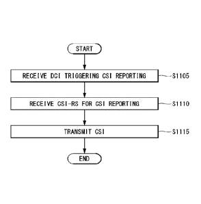
[25] FIG. 11 shows an example of an operating flowchart of a terminal
reporting channel
state information according to some implementations of this disclosure;
[26] FIG. 12 shows an example of an operating flowchart of a base station
receiving
channel state information according to some implementations of this
disclosure;
[27] FIG. 13 shows an example of a wireless communication device according
to some
implementations of the present disclosure; and
[28] FIG. 14 shows another example of a block diagram of a wireless
communication
device according to some implementations of this disclosure.
Description of Example Embodiments
[29] Implementations of the present disclosure generally enable
transmitting and receiving
channel state information (CSI) in a wireless communication system.
[30] According to some implementations, techniques are disclosed for
allocating and/or
assigning one or more CSI reportings, configured and/or indicated by a base
station, to
one or more processing units that are utilized by a corresponding terminal
when the
terminal calculates CSI.
[31] Furthermore, according to some implementations, techniques are
disclosed for al-
locating and/or assigning a minimum required time (e.g., Z value) and/or a
minimum
number of processing unit utilized by the terminal for the CSI reporting,
which may be
applied when CSI reporting for beam management and/or beam reporting use, that
is,
L1-RSRP report, is performed.
[32] Hereinafter, some implementations of the present disclosure are
described in detail
with reference to the accompanying drawings. A detailed description to be
disclosed
along with the accompanying drawings is intended to describe some exemplary
imple-
mentations of the present disclosure and is not intended to describe a sole
imple-
mentation of the present disclosure. The following detailed description
includes more
details in order to provide full understanding of the present disclosure.
However, those
skilled in the art will understand that the present disclosure may be
implemented
without such more details.
[33] In some cases, in order to avoid making the concept of the present
disclosure vague,
known structures and devices are omitted or may be shown in a block diagram
form
based on the core functions of each structure and device.
Date Recue/Date Received 2020-05-04
CA 03081676 2020-05-04
WO 2020/032432 PCT/KR2019/009127
6
[34] Hereinafter, downlink (DL) means communication from a base station to
a terminal,
and uplink (UL) means communication from a terminal to a base station. In
downlink,
a transmitter may be part of a base station, and a receiver may be part of a
terminal. In
uplink, a transmitter may be part of a terminal, and a receiver may be part of
a base
station. A base station may be represented as a first communication device,
and a
terminal may be represented as a second communication device. A base station
(BS)
may be substituted with a term, such as a fixed station, an evolved-NodeB
(eNB), a
next generation NodeB (gNB), a base transceiver system (BTS), an access point
(AP),
a network (5G network), an Al system, a road side unit (RSU) or a robot.
Furthermore,
a terminal may be fixed or may have mobility, and may be substituted with a
term,
such as a user equipment (UE), a mobile station (MS), a user terminal (UT), a
mobile
subscriber station (MSS), a subscriber station (SS), an advanced mobile
station (AMS),
a wireless terminal (WT), a machine-type communication (MTC) device, a machine-
to-machine (M2M) device, a device-to-device (D2D) device, a vehicle, a robot
or an
Al module.
[35[ The following technology may be used for various radio access systems,
such as
CDMA, FDMA, TDMA, OFDMA, and SC-FDMA. CDMA may be implemented as a
radio technology, such as universal terrestrial radio access (UTRA) or
CDMA2000.
TDMA may be implemented as radio technology, such as a global system for
mobile
communications (GSM)/general packet radio service (GPRS)/enhanced data rates
for
GSM evolution (EDGE). OFDMA may be implemented as a radio technology, such as
IEEE 802.11 (Wi-Fi), IEEE 802.16 (WiMAX), IEEE 802-20, or evolved UTRA
(E-UTRA). UTRA is part of a universal mobile telecommunications system (UMTS).
3 rd generation partnership project (3GPP) long term evolution (LTE) is part
of an
evolved UMTS (E-UMTS) using E-UTRA, and LTE-Advanced (A)/LTE-A pro is an
evolved version of 3GPP LTE. A 3GPP new radio or new radio access technology
(NR) is an evolved version of 3GPP LTE/LTE-A/LTE-A pro.
[36] In order to clarify the description, a 3GPP communication system
(e.g., LTE-A, NR)
is basically described, but the technical spirit of the present disclosure is
not limited
thereto. LTE means a technology after a 3GPP TS 36.xxx Release 8.
Specifically, an
LTE technology after 3GPP TS 36.xxx Release 10 is denoted as LTE-A, and an LTE
technology after 3GPP IS 36.xxx Release 13 is denoted as LTE-A pro. 3GPP NR
means a technology after TS 38.xxx Release 15. LTE/NR may be denoted as a 3GPP
system. "xxx'' means a detailed number of the standard document. LTE/NR may be
commonly called a 3GPP system. For the background technology, terms, and abbre-
viations used in the description of the present disclosure, reference may be
made to
contents described in the standard document disclosed prior to the present
disclosure.
For example, reference may be made to the following documents.
CA 03081676 2020-05-04
WO 2020/032432 PCT/KR2019/009127
7
[37] 3GPP LTE
[38] - 36.211: Physical channels and modulation
[39] - 36.212: Multiplexing and channel coding
[40] - 36.213: Physical layer procedures
[41] - 36.300: Overall description
[42] - 36.331: Radio Resource Control (RRC)
[43] 3GPP NR
[44] - 38.211: Physical channels and modulation
[45] - 38.212: Multiplexing and channel coding
[46] - 38.213: Physical layer procedures for control
[47] - 38.214: Physical layer procedures for data
[48] - 38.300: NR and NG-RAN Overall Description
[49] - 36.331: Radio Resource Control (RRC) protocol specification
[50] As more communication devices require a higher communication capacity,
there
emerges a need for enhanced mobile broadband communication compared to the
existing radio access technology. Furthermore, massive machine type
communications
(MTC) that provides various services anywhere and at anytime by connecting
multiple
devices and things is also one of major issues that will be taken into
consideration in
next-generation communication. Furthermore, a communication system design in
which service/terminal sensitive to reliability and latency is taken into
consideration is
discussed. As described above, the introduction of a next-generation radio
access
technology in which enhanced mobile broadband communication (eMBB), massive
MTC (Mmtc), ultra-reliable and low latency communication (URLLC), etc. are
taken
into consideration is discussed. In this disclosure, the corresponding
technology is
called NR, for convenience sake. NR is an expression showing an example of a
5G
radio access technology (RAT)).
[51] A new RAT system including NR uses an OFDM transmission technique or a
transmission technique similar to OFDM transmission. The new RAT system may
comply with OFDM parameters different from OFDM parameters of LTE. Alter-
natively, the new RAT system may comply with the numerology of the existing
LTE/
LTE-A or may have a greater system bandwidth (e.g., 100 MHz). Alternatively,
one
cell may support a plurality of numerologies. That is, terminals operating in
different
numerologies may coexist within one cell.
[52] Numerology corresponds to one subcarrier spacing in a frequency
domain. A
different numerology may be defined by scaling reference subcarrier spacing
using an
integer N.
[53] Three major requirement areas of 5G includes (1) an enhanced mobile
broadband
(eMBB) area, (2) a massive machine type communication (mMTC) area and (3) an
CA 03081676 2020-05-04
WO 2020/032432 PCT/KR2019/009127
8
ultra-reliable and low latency communications (URLLC) area.
[541 Some use cases may require multiple areas for optimization, and other
use cases may
be focused on only one key performance indicator (KPI). 5G supports such
various use
cases in a flexible and reliable manner.
[551 eMBB enables basic mobile Internet access to be greatly surpassed, and
covers
abundant directional tasks and media and entertainment applications in cloud
or
augmented reality. Data is one of core power of 5G. Dedicated voice service
may not
be first seen in the 5G era. In 5G, it is expected that voice will be
processed as an ap-
plication program using a data connection simply provided by a communication
system. Major causes of an increased traffic volume include an increase of a
content
size and an increase in the number of applications that require a high data
transfer rate.
Streaming service (audio and video), dialogue video, and a mobile Internet
connection
will be more widely used as more devices are connected to the Internet. Such
many ap-
plication programs require connectivity in which the programs are always
turned on in
order to push real-time information and notification to a user. Cloud storage
and ap-
plications rapidly increase in mobile communication platforms, which may be
applied
to both business and entertainment. Furthermore, cloud storage is a special
use case
that pulls the growth of an uplink data transfer rate. 5G is also used for
remote business
of cloud, and requires much lower end-to-end latency in order to maintain
excellent
user experiences when a tactile interface is used. Entertainment, for example,
cloud
game and video streaming are other core elements that increase needs for a
mobile
wideband capability. Entertainment is essential for smartphones and tablets
anywhere,
including high mobility environments, such as a train, vehicle and airplane.
Another
use case is augmented reality and information search for entertainment. In
this case,
augmented reality requires very low latency and an instant data volume.
[56] Furthermore, one of 5G use cases that is most expected is related to a
function
capable of smoothly connecting embedded sensors in all the fields, that is,
mMTC. It is
expected that potential IoT devices will reach 20.4 billions until 2020. In
industry IoT,
5G is one of regions performing major roles that enable a smart city, asset
tracking, a
smart utility, agriculture and security infra.
[57l1 URLLC includes a new service that will change the industry through a
link having
ultra-reliability/available low latency, such as remote control of major infra
and a self-
driven vehicle. A level of reliability and latency is essential for smart grid
control,
industry automation, robot engineering, drone control and adjustment.
[581 Multiple use cases are described more specifically.
f59ll 5G is means for providing a stream evaluated as Giga bits per second
in several
hundreds of mega bits per second, and may supplement for fiber-to-the-home
(FTTH)
and cable-based wideband (or DOCSIS). Such a fast speed is necessary to
deliver TV
CA 03081676 2020-05-04
WO 2020/032432 PCT/KR2019/009127
9
with resolution of 4K or more (6K, 8K and more) in addition to virtual reality
and
augmented reality. Virtual reality (VR) and augmented reality (AR)
applications
include nearly immersive sports. A specific application program may require a
special
network configuration. For example, in the case of VR game, in order for game
companies to minimize latency, a core server may need to be integrated with an
edge
network server of a network operator.
[60] It is expected that an automotive will become important new power in
5G along with
many use cases for mobile communication for an automotive. For example, enter-
tainment for a passenger requires both a high capacity and a high mobility
mobile
wideband. The reason for this is that a future user will continue to expect a
connection
of high quality regardless of his or her location and speed. Another use
example of the
automotive field is an augmented reality dashboard. The augmented reality
dashboard
enables a driver to identify an object in the dark on a thing reported through
the front
window, and overlaps and displays information spoken to the driver with
respect to the
distance and movement of the object. In the future, a wireless module enables
commu-
nication between vehicles, information exchange between a vehicle and a
supported in-
frastructure, and information exchange between a vehicle and other connected
devices
(e.g., devices accompanied by a pedestrian). A safety system shows alternative
courses
of a behavior so that a driver can drive more safely, thereby being capable of
reducing
a danger of an accident. A next step will be a remote-controlled or self-
driven vehicle.
This requires very reliable and very fast communication between different self-
driven
vehicles and between a vehicle and infra. In the future, a self-driven vehicle
may
perform all driving activities, and a driver will be focused on only traffic
abnormality
that cannot be identified by a vehicle itself. Technical requirements of a
self-driven
vehicle include ultra-low latency and ultra-high speed reliability so that
traffic safety is
increased up to a level of the extent that that cannot be achieved by a
person.
[61] A smart city and a smart home mentioned as a smart society will be
embedded as a
high density wireless sensor network. A distributed network of intelligent
sensors will
identify a condition for the cost- and energy-efficient maintenance of a city
or house. A
similar configuration may be performed for each home. All of a temperature
sensor, a
window, a heating controller, a burglar alarm and home appliances are
connected
wirelessly. Many of such sensors are typically a low data transmission speed,
low
energy and a low cost. However, for example, real-time HD video may be
necessary in
a specific type of a device for surveillance.
[62] The consumption and distribution of energy including heat or gas
require automated
control of a distributed sensor network because they are highly distributed. A
smart
grid collects information, and interconnects such sensors using digital
information and
communication technologies so that the sensors behavior based on the
information.
CA 03081676 2020-05-04
WO 2020/032432 PCT/KR2019/009127
The information may include supplier and consumer behaviors, so the smart grid
can
improve the distribution of fuel, such as electricity, in manners, such as
efficiency, re-
liability, economics, production sustainability and automation. The smart grid
may be
considered to be a different sensor network having low latency.
[63] A health sector includes many application programs that may reap the
benefits of
mobile communication. A communication system may support remote medical
treatment that provides clinical medical treatment at a remote place. This may
help to
reduce a barrier for the distance and to improve access to medical services
that are not
continuously used at a remote farming area. This is also used to save life in
medical
treatment and an urgent situation. A mobile communication-based wireless
sensor
network may provide remote monitoring and sensors for parameters, such as a
heart
rate and blood pressure.
[64] Wireless and mobile communication becomes more important in the
industry ap-
plication field. An installation and maintenance cost for wires is high.
Accordingly, the
possibility that the wires are substituted with radio links capable of
reconfiguring a
cable is an attractive opportunity in many industry fields. However, to
achieve the op-
portunity requires that a wireless connection operates with latency,
reliability and
capacity similar to those of the cable and that management thereof is
simplified. A low
latency and very low error probability is a new requirement that needs to be
connected
to 5G.
1651 Logistics and freight tracking are an important use case for mobile
communication,
which enables the tracking of an inventory and package anywhere using a
location-
based information system. A use case of logistics and freight tracking
typically
requires a low data speed, but requires a wide area and reliable location
information.
[66] Definition of terms
1671 eLTE eNB: An eLTE eNB is an evolution of an eNB that supports a
connection for
an EPC and an NGC.
[68] gNB: A node for supporting NR in addition to a connection with an NGC
[69] New RAN: A radio access network that supports NR or E-UTRA or
interacts with an
NGC
1701 Network slice: A network slice is a network defined by an operator so
as to provide a
solution optimized for a specific market scenario that requires a specific
requirement
together with an inter-terminal range.
[71] Network function: A network function is a logical node in a network
infra that has a
well-defined external interface and a well-defined functional operation.
1721 NO-C: A control plane interface used for NG2 reference point between
new RAN
and an NGC
11731 NG-U: A user plane interface used for NG3 reference point between new
RAN and
CA 03081676 2020-05-04
WO 2020/032432 PCT/KR2019/009127
11
an NGC
[74] Non-standalone NR: A deployment configuration in which a gNB requires
an LTE
eNB as an anchor for a control plane connection to an EPC or requires an eLTE
eNB
as an anchor for a control plane connection to an NGC
[75] Non-standalone E-UTRA: A deployment configuration an eLTE eNB requires
a gNB
as an anchor for a control plane connection to an NGC.
[76] User plane gateway: A terminal point of NG-U interface
[77] General system
[78] FIG. 1 is a diagram illustrating an example of an overall structure of
a new radio
(NR) system according to some implementations of the present disclosure.
[79] Referring to FIG. 1, an NG-RAN is configured with gNBs that provide an
NG-RA
user plane (new AS sublayer/PDCP/RLC/MAC/PHY) and a control plane (RRC)
protocol for a user equipment (UE).
[80] The gNBs are connected to each other via an Xn interface.
[81] The gNBs are also connected to an NGC via an NG interface.
[82] More specifically, the gNBs are connected to an access and mobility
management
function (AMF) via an N2 interface and a user plane function (UPF) via an N3
interface.
[83] New Rat (NR) Numerology and frame structure
[84] In the NR system, multiple numerologies may be supported. The
numerologies may
be defined by subcarrier spacing and a cyclic prefix (CP) overhead. Spacing
between
the plurality of subcarriers may be derived by scaling basic subcarrier
spacing into an
integer N (or g). In addition, although a very low subcarrier spacing is
assumed not to
be used in a very high subcarrier frequency, a numerology to be used may be
selected
regardless of a frequency band.
[85] In addition, in the NR system, a variety of frame structures according
to the multiple
numerologies may be supported.
[86] Hereinafter, an orthogonal frequency division multiplexing (OFDM)
numerology and
a frame structure, which may be considered in the NR system, will be
described.
[87] A plurality of OFDM numerologies supported in the NR system may be
defined as in
Table 1.
[88] [Table 1]
AI \f-2'1=111.11/1 Cyclic prefix
0 15 Normal
1 30 Normal
2 60 Normal, Extended
3 120 Normal
4 240 Normal
480 Normal
CA 03081676 2020-05-04
WO 2020/032432
PCT/KR2019/009127
12
[89] Regarding a frame structure in the NR system, the size of various
fields in the time
domain is expressed as a multiple of a time unit of Ts=11(Afina,.Nt). In this
case,
44,m = 480103, and Nf = 4096. DL and UL transmission is configured as a radio
frame
having a section of rf _
.Nf1100)=T =10ms. The radio frame is composed of
ten subframes each having a section of rr f
= (AfingõN, 11000)=Ts,ims. In this case,
there may be a set of UL frames and a set of DL frames.
[90] FIG. 2 illustrates a relationship between a UL frame and a DL frame in
a wireless
communication system according to some implementations of the present
disclosure.
[91] As illustrated in FIG. 2, an UL frame number I from a user equipment
(UE) needs to
be transmitted TTA = NTAT before the start of a corresponding DL frame in the
UE.
[92] Regarding the numerology I-1, slots are numbered in ascending powers
of
n;" E to,.., Arsttsfr-". ¨11 in a subframe, and in ascending powers of
/1/1 E (0 Nslots,it in a
radio frame. One slot is composed of continuous OFDM
s,f = ' = ^ frame
symbols of i'Vb, and Nsm,b is determined based on a used numerology and slot
con-
figuration. The start of slots ii`` in the subframe is temporally aligned with
the start of
OFDM symbols in the same subframe.
[93] All the terminals cannot perform transmission and reception at the
same time, which
means that all the OFDM symbols of a downlink slot or uplink slot cannot be
used.
[94] Table 2 shows the number of OFDM symbols ( zykilltb) for each slot,
the number of
slots ( Nn7-") for each radio frame, and the number of slots
Nssiuobtflarne,t') for each
subframe in a normal CP. Table 3 shows the number of OFDM symbols for each
slot,
the number of slots for each radio frame, and the number of slots for each
subframe in
an extended CP.
[95] [Table 2]
11 N'1 symb ATfiame,p
slot vsubframe,
p
slot
0 14 10
1 14 20 2
2 14 40 4
3 14 80 8
4 14 160 16
[96] [Table 3]
ivssylomtb ,frame ,u Nsubframe,ii
slot slot
2 12 40 4
[97] FIG. 3 shows an example of a frame structure in an NR system. FIG. 3
is merely for
CA 03081676 2020-05-04
WO 2020/032432
PCT/KR2019/009127
13
convenience of description and does not limit the scope of the present
disclosure.
[98] Table 3 is an example in which ji=2. that is, subcarrier spacing (SCS)
is 60 kHz.
Referring to Table 2, 1 subframe (or frame) may include 4 slots. A 1
subframe={1,2,41
slots shown in FIG. 3 is an example, and the number of slots that may be
included in 1
subframe may be defined like Table 2.
[99] Furthermore, a mini-slot may be configured with 2, 4 or 7 symbols and
may be
configured with symbols more or less symbols than the 2, 4 or 7 symbols.
[100] In relation to a physical resource in the NR system, an antenna port,
a resource grid, a
resource element, a resource block, a carrier part may be taken into
consideration.
[101] Hereinafter, the above physical resources possible to be considered
in the NR system
will be described in more detail.
[102] First, regarding an antenna port, the antenna port is defined such
that a channel over
which a symbol on one antenna port is transmitted can be inferred from another
channel over which a symbol on the same antenna port is transmitted. When
large-
scale properties of a channel received over which a symbol on one antenna port
can be
inferred from another channel over which a symbol on another antenna port is
transmitted, the two antenna ports may be in a quasi co-located or quasi co-
location
(QC/QCL) relationship. In this case, the large-scale properties may include at
least one
of delay spread, Doppler spread, Doppler shift, average gain, and average
delay.
[103] FIG. 4 illustrates an example of a resource grid supported in a
wireless commu-
nication system according to some implementations of the present disclosure.
[104] Referring to FIG. 4, a resource grid is composed of N, Ars'r
subcarriers in a
frequency domain, each subframe composed of 14x2Au OFDM symbols, but the
present disclosure is not limited thereto.
[105] In the NR system, a transmitted signal is described by one or more
resource grids,
composed of N/v.r subcarriers, and 2"N,(y"), OFDM symbols, wherein Ni';3
The above AZ'indicates the maximum transmission bandwidth, and it may change
not just between numerologies, but between UL and DL.
[106] In this case, as illustrated in FIG. 5, one resource grid may be
configured for the nu-
merology /1 and an antenna port p.
[107] FIG. 5 illustrates examples of resource grids for each antenna port
and numerology
according to some implementations of this disclosure.
[108] Each element of the resource grid for the numerology and the antenna
port p is
indicated as a resource element, and may be uniquely identified by an index
pair (k,1).
In this case, k = IkTN,RB, -1 is an index in the frequency domain, and
/ = 0, ...,2/` N, -1 indicates a location of a symbol in a subframe. To
indicate a
resource element in a slot, the index pair (k,i) is used. In this case, 1 =
-1.
CA 03081676 2020-05-04
WO 2020/032432 PCT/KR2019/009127
14
[109] A resource element (c,i) for a numerology and an antenna port p
corresponds to a
complex value ak(r) . If there is no danger of confusion or if a specific
antenna port or
numerology is not specified, indices p and P may be dropped. As a result, a
complex
value may be ce or ak,l.
[110] Furthermore, a physical resource block is defined as N =12 contiguous
subcarriers
on the frequency domain.
[111] A point A plays a role as a common reference point of a resource
block grid and may
be obtained as follows.
[112] - offsetToPointA for PCell downlink indicates a frequency offset
between the lowest
subcarrier of the lowest resource block, overlapping an SS/PBCH block used for
a UE
for initial cell selection, and the point A, and is represented as a resource
block units
assuming a 15 kHz subcarrier spacing for FR1 and a 60 kHz subcarrier spacing
for
FR2;
11131 - absoluteFrequencyPointA indicates the frequency-location of the
point A rep-
resented as in an absolute radio-frequency channel number (ARFCN).
[114] Common resource blocks are numbered from 0 to the upper side in the
frequency
domain for the subcarrier spacing configuration
[115] The center of the subcarrier 0 of a common resource block 0 for the
subcarrier
spacing configuration" is identical with the 'point A.' A resource element
(k,l) for a
common resource block number n&B and the subcarrier spacing configuration in
the
frequency domain may be given like Equation 1 below.
[116] [Equation 1]
[117]
µ13
h:
ncRi3 ¨,vpc,
[118] In this case, may be relatively defined at the point A so that k
corresponds to a
subcarrier having the point A as the center. Physical resource blocks are
numbered
from 0 to ivisEgp, -1 within a bandwidth part (BWP). is the number of a BWP.
In the
BWP i, the relation between the physical resource block "PRE' and the common
resource
block ncRn may be given by Equation 2 below.
[119] [Equation 2]
[120] ',Gus = nPRB WSVaftT,'
[121] In this case, N 15311EVIP , may be a common resource block in which
the BWP relatively
starts in the common resource block 0.
[122] Bandwidth part (BWP)
[123] An NR system may be supported up to a maximum of 400 MHz per one
component
carrier (CC). If a terminal operating in such a wideband CC operates with its
RF for all
CCs being turned on, terminal battery consumption may be increased.
Alternatively, if
CA 03081676 2020-05-04
WO 2020/032432 PCT/KR2019/009127
several use cases (e.g., eMBB, URLLC, Mmtc, V2X) operating within one wideband
CC are taken into consideration, a different numerology (e.g., sub-carrier
spacing) for
each frequency band within the corresponding CC may be supported.
Alternatively, the
capability of a maximum bandwidth may be different for each terminal. A base
station
may indicate that the terminal operates only in some bandwidth not the full
bandwidth
of the wideband CC by taking the capacity into consideration. The
corresponding some
bandwidth is defined as a bandwidth part (BWP), for convenience sake. The BWP
may
be configured with resource blocks (RBs) contiguous on a frequency axis, and
may
correspond to one numerology (e.g., sub-carrier spacing, CP length, slot/mini-
slot
duration).
[124] Meanwhile, a base station may configure multiple BWPs within one CC
configure in
a terminal. For example, in a PDCCH monitoring slot, a BWP occupying a
relatively
small frequency domain may be configured, and a PDSCH indicated in a PDCCH may
be scheduled on a BWP greater than the configured BWP. Alternatively, if UEs
are
crowded in a specific BWP, some UEs may be configured in other BWP for load
balancing. Alternatively, some spectrum at the center of a full bandwidth may
be
excluded by taking into consideration frequency domain inter-cell interference
can-
cellation between neighbor cells, and BWPs on both sides may be configured in
the
same slot. That is, the base station may configure at least one DL/UL BWP in a
terminal associated with a wideband CC, may activate at least one DL/UL BWP of
DL/UL BWP(s) (by Li signaling or MAC CE or RRC signaling) configured in a
specific time. Switching to another configured DL/UL BWP (by Li signaling or
MAC
CE or RRC signaling) may be indicated or switching to a predetermined DUUL BWP
may be performed when a timer value expires based on a timer. In this case,
the
activated DL/UL BWP is defined as an active DL/UL BWP. However, if a terminal
is
in an initial access process or in a situation before an RRC connection is set
up, the
terminal may not receive a configuration for a DL/UL BWP. In such a situation,
a DL/
UL BWP assumed by the terminal is defined as an initial active DL/UL BWP.
[125] Self-contained structure
[126] A time division duplexing (TDD) structure taken into consideration in
an NR system
is a structure in which both uplink (UL) and downlink (DL) are processed in
one slot
(or subframe). This is for minimizing latency of data transmission in the TDD
system.
The structure may be referred to as a self-contained structure or a self-
contained slot.
[127] FIG. 6 shows an example of a self-contained structure according to
some imple-
mentations of this disclosure. FIG. 6 is merely for convenience of description
and does
not limit the scope of the present disclosure.
[128] Referring to FIG. 6, as in the case of legacy LTE, a case where one
transmission unit
(e.g., slot, subframe) is configured with 14 orthogonal frequency division
multiplexing
CA 03081676 2020-05-04
WO 2020/032432 PCT/KR2019/009127
16
(OFDM) symbols is assumed.
[129] In FIG. 6, a region 602 means a downlink control region, and a region
604 means an
uplink control region. Furthermore, regions (i.e., regions not having separate
in-
dication) except the region 602 and the region 604 may be used for the
transmission of
downlink data or uplink data.
[130] That is, uplink control information and downlink control information
may be
transmitted in one self-contained slot. In contrast, in the case of data,
uplink data or
downlink data may be transmitted in one self-contained slot.
[131] If the structure shown in FIG. 6 is used, downlink transmission and
uplink
transmission are sequentially performed and the transmission of downlink data
and the
reception of uplink ACK/NACK may be performed within one self-contained slot.
[132] Consequently, when an error occurs in data transmission, the time
consumed up to
the retransmission of data can be reduced. Accordingly, latency related to
data
forwarding can be minimized.
[133] In a self-contained slot structure, such as FIG. 6, there is a need
for a time gap for a
process of a base station (eNodeB, eNB, gNB) and/or a terminal (user equipment
(UE)) changing from a transmission mode to a reception mode or of the base
station
and/or the terminal changing from a reception mode to a transmission mode. In
relation
to the time gap, when uplink transmission is performed after downlink
transmission in
a self-contained slot, some OFDM symbol(s) may be configured as a guard period
(GP).
[134] The following contents are discussed in relation to CSI measurement
and/or
reporting.
[135] As used herein, the parameter Z refers to a minimum required time for
a terminal to
perform CSI reporting, e.g., a minimum time duration (or time gap) starting
from a
timing at which a terminal receives DCI that schedules the CSI reporting until
a timing
at which the terminal performs actual CSI reporting.
[136] Furthermore, a time offset of a CSI reference resource may be derived
based on a
minimum time duration starting from a timing at which a terminal receives a
mea-
surement resource (e.g., CSI-RS) related to CSI reporting until a timing at
which the
terminal performs actual CSI reporting (referred to herein as Z') and based on
a nu-
merology (e.g., subcanier spacing) for CSI latency.
[137] Specifically, in relation to the calculation (or computation) of CSI,
Z and Z' values
may be defined as in the examples of Table 4 to Table 7. In this case, Z is
related to
only aperiodic CSI reporting. For example, the Z value may be represented as
the sum
of a decoding time for DCI (scheduling CSI reporting) and a CSI processing
time (e.g.,
Z' to be described later). Furthermore, in the case of a Z value of a normal
terminal, a
channel state information-reference signal (CSI-RS) may be assumed to be
positioned
CA 03081676 2020-05-04
WO 2020/032432
PCT/KR2019/009127
17
after the last symbol of a PDCCH symbol (i.e., the symbol of a PDCCH in which
DCI
is transmitted).
[138] Furthermore, as discussed above, the parameter Z' may refer to a
minimum duration
(or time gap) from a timing at which a terminal receives a measurement
resource (i.e.,
CMR, IMR) (e.g., CSI-RS) related to CSI reporting to a timing at which the
terminals
performs actual CSI reporting. In general, a relation may be described between
(Z, Z')
and numerology and CSI latency, as shown in the example of Table 4.
[139] [Table 4]
CSI latency Units 15kHz SCS 30kHz SCS 60kHz
SCS 120kHz SCS
Low latency Symbols (Z11, Z'11) (Z12, Z'12) (Z3,
Z'13) (Zi 4, Z1 4)
High latency Symbols (Z21, Z'21) (Z22, Z'22) (Z23,
Z'23) (Z24, Z'24)
[140] Furthermore, Table 5 and Table 6 show examples of CSI calculation
times for a
normal UE and CSI calculation times for an advanced UE, respectively. Table 5
and
Table 6 are merely examples and are not limiting.
[141] [Table 5]
CSI latency Units 15kHz SCS 30kHz SCS 60kHz
SCS 120kHz SCS
(ji=O)(t=1) (ji =
2)(t=3)
Low latency Symbols (22, 15) (25, 16) (33, 19) (49, 25)
High latency Symbols (29, 22) (32, 23) (40, 26) (56, 32)
[142] [Table 6]
cs1 latency Units 15kHz SCS 30kHz SCS 60kHz
SCS 120kHz SCS
(pt = 0) (ki = 1) = 2) (11 = 3)
Low latency Symbols (12, 7) (12, 7) (12, 7) (12, 7)
High latency Symbols (19, 14) (19, 14) (19, 14) (19, 14)
[143] Furthermore, in relation to the above-described CSI latency, it may
be assumed that
when N CSI reportings are triggered, up to X CSI reportings will be calculated
in a
given time. In this case, X may be based on UE capability information.
Furthermore, in
relation to the above-described Z (and/or Z'), a terminal may be configured to
ignore
DCI scheduling CSI reporting that does not satisfy a condition related to the
Z value.
[144] Furthermore, information (i.e., information for (Z, Z')) related to
CSI latency, such as
that described above, may be reported (to the base station) as UE capability
in-
formation by a terminal.
[145] For example, if aperiodic CSI reporting through only a PUSCH
configured as single
CSI reporting is triggered, a terminal may not expect that it will receive
scheduling
downlink control information (DCI) having a symbol offset, such as 'M-L-N <Z.
Fur-
thermore, if an aperiodic channel state information-reference signal (CSI-RS)
is used
for channel measurement and has a symbol offset, such as 'M-O-N < Z', a
terminal may
not expect that it will receive scheduling DCI.
[146] In the above description, L may indicate the last symbol of a PDCCH
triggering
aperiodic reporting, M may indicate the starting symbol of a PUSCH, and N may
indicate a timing advanced (TA) value of a symbol unit. Furthermore, 0 may
mean the
CA 03081676 2020-05-04
WO 2020/032432
PCT/KR2019/009127
18
latest symbol of the last symbol of an aperiodic CSI-RS for a channel
measurement
resource (CMR), the last symbol (if present) of an aperiodic non zero power
(MZP)
CSI-RS for an interference measurement resource (IMR), and the last symbol (if
present) of aperiodic channel state information-interference measurement (CSI-
IM).
The CMR may mean an RS and/or resource for channel measurement, and the IMR
may mean an RS and/or resource for interference measurement.
[147] In relation to the above-described CSI reporting, a case where CSI
reportings collide
against each other may occur. In this case, the collision of the CSI
reportings may
mean that the time occupancies of physical channels scheduled to transmit CSI
re-
portings overlap in at least one symbol and are transmitted in the same
carrier. For
example, if 2 or more CSI reportings collide against each other, one CSI
reporting may
be performed according to the following rule. In this case, priority of CSI
reporting
may be determined using a sequential technique of first applying Rule #1 and
then
applying Rule #2. Rule #2, Rule #3, and Rule #4 of the following rules may be
applied
to only all periodic reporting and semi-persistently reporting aimed at a
PUCCH.
[148] - Rule #1: in the operating viewpoint on a time domain, aperiodic
(AP) CS1 >
PUSCH-based semi-persistent (SP) CSI > PUCCH-based semi-persistent CSI >
periodic (P) CSI
[149] - Rule #2: in the CSI content viewpoint, beam management (e.g., beam
reporting)-related CSI > CSI acquisition-related CSI
[150] - Rule #3: in the cell ID (cellID) viewpoint, a primary cell (PCell)
> a primary
secondary cell (PSCell) > different IDs (in increasing order)
[151] - Rule #4: in the CSI reporting-related ID (e.g., csiReportID)
viewpoint, in order that
the indices of IDs increase
[152] Furthermore, in relation to the above-described CSI reporting, a
processing unit (e.g.,
CPU) may be defined. For example, a terminal supporting X CS! calculations
(e.g.,
based on UE capability information 2-35) may mean that the terminal utilizes X
processing units to report CSI. In this case, the number of CSI processing
units may be
represented as K_s.
[153] For example, in the case of aperiodic CSI reporting using an
aperiodic CSI-RS
(configured with a single CSI-RS resource in a resource set for channel
measurement),
a CSI processing unit may be maintained in the state in which symbols from the
first
OFDM symbol to the last symbol of a PUSCH carrying CSI reporting after PDCCH
triggering have been occupied.
11541 For another example, if N CSI reportings (each one being
configured with a single
CSI-RS resource in a resource set for channel measurement) are triggered in a
slot, but
a terminal has only M un-occupied CSI processing units, the corresponding
terminal
may be configured to update (i.e., report) only M of the N CSI reportings.
CA 03081676 2020-05-04
WO 2020/032432 PCT/KR2019/009127
19
[155] Furthermore, in relation to the above-described X CSI calculations.
the UE capability
may be configured to support any one of a Type CSI processing capability or a
Type B
CSI processing capability.
[156] For example, it is assumed that an aperiodic CSI trigger state (A-CSI
trigger state
triggers N CSI reportings (in this case, each CSI reporting is associated with
(Z_n,
Zin)) and has un-occupied CSI processing units.
[157] In the case of the Type CSI processing capability, if a time gap
between the first
symbol of a PUSCH and the last symbol related to aperiodic CSI-RS/aperiodic
CSI-IM
does not have a sufficient CSI calculation time according to z7.', = M z', a
terminal
may not expect that any one of triggered CSI reportings will be updated.
Furthermore,
the terminal may ignore DCI scheduling a PUSCH having a scheduling offset
smaller
than 40T = LAI Z' =
n-1
[158] In the case of the Type B CSI processing capability, if a PUSCH
scheduling offset
does not have a sufficient a CSI calculation time according to a corresponding
Z' value
in corresponding reporting, a terminal may not expect that CSI reporting will
be
updated. Furthermore, the terminal may ignore DCI scheduling a PUSCH having a
scheduling offset smaller than any one of Z values for other reportings.
[159] For another example, CSI reporting based on a periodic and/or semi-
persistent CSI-
RS may be assigned to a CSI processing unit depending on a Type A method or a
Type
B method. The Type A method may assume a serial CSI processing implementation,
and the Type B method may assume a parallel CSI processing implementation.
[160] In the Type A method, in the case of periodic and/or semi-persistent
CSI reporting, a
CSI processing unit may occupy symbols from the first symbol of a CSI
reference
resource of periodic and/or semi-persistent CSI reporting to the first symbol
of a
physical channel carrying corresponding CSI reporting. In the case of
aperiodic CSI
reporting, a CSI processing unit may occupy symbols from the first symbol
after a
PDCCH triggering corresponding CSI reporting to the first symbol of a physical
channel carrying corresponding CSI reporting.
[161] In the Type B method, periodic or aperiodic CSI reporting setting
based on a periodic
and/or semi-persistent CSI-RS may be allocated to one or K_s CSI processing
units,
and may always occupy one or K_s CSI processing units. Furthermore, activated
semi-
persistent CSI reporting setting may be allocated to one or K_s CSI processing
units,
and may occupy one or K_s CSI processing units until it is deactivated. When
semi-
persistent CSI reporting is activated, a CSI processing unit may be used for
other CSI
reporting.
[162] Furthermore, in the case of the above-described Type CSI processing
capability,
when the number of CSI processing units occupied by periodic and/or semi-
persistent
CA 03081676 2020-05-04
WO 2020/032432 PCT/KR2019/009127
CSI reporting exceeds the number of simultaneous CSI calculations (X)
according to
UE capability, a terminal may not expect that the periodic and/or semi-
persistent CSI
reporting will be updated.
[163] First implementation
[164] In the present implementation, examples of configuring the
assignment, allocation
and/or occupancy of a CSI processing unit for one or more CSI reportings are
described.
[165] In relation to the above-described processing unit (e.g., CPU), a
rule for determining
which CST will use a CSI processing unit, that is, which CST will be allocated
to a CSI
processing unit, needs to be taken into consideration. In this disclosure, in
relation to a
CSI processing unit, CSI will mean or denote CSI reporting.
[166] For convenience of description, in the present implementation, a case
where a
terminal has X CSI processing units, X-M CSI processing units of the X CSI
processing units are occupied (i.e., used) for CST calculation, and M CSI
processing
units are not occupied is assumed. That is, M may mean the number of CSI
processing
units not occupied by CSI reporting.
[167] In this case, at specific timing (e.g., a specific OFDM symbol). N
CSI reportings
greater than M may start the occupancy of a CSI processing unit.
[168] For example, when the occupancy (i.e., use) of a CSI processing unit
starts with
respect to 3 CSI reportings in the state in which M is 2 in an n-th OFDM
symbol, only
two of 3 CSI reportings occupy the CSI processing unit. In this case, a CSI
processing
unit is not allocated (or assigned) to the remaining one CSI reporting, and
CSI for the
corresponding CSI reporting cannot be calculated. With respect to the not-
calculated
CSI, a technique of defining (or agreeing) that the most recently calculated
and/or
reported CSI is reported again or defining (or agreeing) that a preset
specific CSI value
is reported or defining (or agreeing that reporting is not performed regarding
the corre-
sponding CSI reporting may be taken into consideration.
[169] Hereinafter, the present implementation utilizes the following
example techniques for
priority regarding which CSI reporting will be first assigned to a CSI
processing unit
(hereinafter priority for CSI processing unit occupancy) when contention for
the
occupancy of the CSI processing unit occurs. Furthermore, the priority for the
occupancy of a CSI processing unit may be configured identically or similarly
in the
above-described CSI collision in addition to the examples to be described
hereinafter.
[170] Example 1)
[171] Priority for the occupancy of a CSI processing unit may be determined
based on a
latency requirement.
[172] In an NR system, all types of CSI may be determined as any one of low
latency CSI
or high latency CSI. In this case, the low latency CSI may mean CSI in which
the
CA 03081676 2020-05-04
WO 2020/032432 PCT/KR2019/009127
21
complexity of a terminal is low in CSI calculation, and the high latency CSI
may mean
CSI in which the complexity of a terminal is high in CSI calculation. For
example,
when CSI is low latency CSI, the corresponding CSI occupies a CSI processing
unit
for a time shorter than that of high latency CSI because the amount of CSI
calculation
is small.
[173] Low latency CSI may be configured to preferentially occupy a CSI
processing unit
over high latency CSI. In this case, there are advantages in that when low
latency CSI
and high latency CSI collide against each other, the occupancy time of a CSI
processing unit can be minimized by giving priority to the low latency CSI and
a corre-
sponding CSI processing unit can be rapidly used for other CSI calculation.
[174] Alternatively, high latency CSI may be configured to preferentially
occupy a CSI
processing unit over low latency CSI. The reason for this is that high latency
CSI has
greater calculation complexity than low latency CSI and can provide more
and/or
accurate channel information.
[175] Example 2)
[176] Priority for the occupancy of a CS1 processing unit may be determined
based on the
occupancy end time of a CSI processing unit.
[177] CSI having a short occupancy end time of a CSI processing unit may be
configured
to preferentially occupy a CSI processing unit.
[178] Although occupancy starting times for a CSI processing unit are the
same for
multiple pieces of CSI (reporting), occupancy end times may be different. For
example, although low latency CSI or high latency CSI are the same, an
occupancy
end time for each CSI reporting may be different depending on a channel for
CSI cal-
culation and/or a CSI-RS whose interference is measured and/or a time domain
behavior (e.g., periodic, semi-persistently, aperiodic) on a CSI-Imdml time
domain.
There are advantages in that the occupancy time of a CSI processing unit can
be
minimized and a corresponding CSI processing unit can be rapidly used for CSI
cal-
culation because CSI having a short occupancy end time is given priority.
[179] Alternatively, CSI having a long (i.e., late) occupancy end time of a
CSI processing
unit may be configured to preferentially occupy a CSI processing unit. The
reason for
this is that CSI having a long occupancy end time requires a long calculation
time and
can provide more and/or accurate channel information.
[180] Example 3)
[181] Priority for the occupancy of a CSI processing unit may be determined
based on a
time domain behavior for a reference signal (e.g., CSI-RS) used for channel
mea-
surement and/or a reference signal (e.g., CSI-1M) used for interference
measurement.
[182] For convenience of description, in this example, in relation to CSI
reporting, a case
where a reference signal used for channel measurement is a CSI-RS and a
reference
CA 03081676 2020-05-04
WO 2020/032432 PCT/KR2019/009127
22
signal used for interference measurement is CSI-IM is assumed.
[183] The CSI-RS and/or the CSI-IM may be transmitted and received in three
types, such
as periodic, semi-persistent, or aperiodic. CSI calculated based on a periodic
CSI-RS
and/or CSI-IM has many opportunities to measure a channel and/or interference.
Ac-
cordingly, CSI calculated based on an aperiodic CSI-RS and/or CSI-IM rather
than
CSI based on a periodic CSI-RS and/or CSI-IM may be preferred to
preferentially
occupy a CSI processing unit.
[184] Accordingly, priority may be determined in order of CSI based on
aperiodic CSI-RS
and/or CSI-IM, CSI based on a semi-persistent CSI-RS and/or CSI-IM, and CSI
based
on a periodic CSI-RS and/or CSI-IM. That is, priority for the occupancy of a
CSI
processing unit may be determined in order of 'CSI based on aperiodic CSI-RS
and/or
CSI-IM > CSI based on a semi-persistent CSI-RS and/or CSI-IM > CSI based on a
periodic CSI-RS and/or CSI-IM. Such priority may be extended and applied to
the
above-described CSI collision rule in addition to priority for the occupancy
of a CSI
processing unit.
11851 Alternatively, priority may be determined in order of CSI based on a
periodic CSI-
RS and/or CSI-IM, CSI based on a semi-persistent CSI-RS and/or CSI-IM, and CSI
based on aperiodic CSI-RS and/or CSI-IM.
[186] Example 4)
11871 Priority for the occupancy of a CSI processing unit may be determined
based on a
time domain measurement behavior.
[188] For example, priority for the occupancy of a CSI processing unit may
be determined
based on whether restriction related to CSI measurement, that is, measurement
re-
striction, has been configured.
[189] When a terminal receives a CSI-RS and/or CSI-IM in a specific time
when the mea-
surement restriction becomes ON and generates CSI by measuring the CSI-RS
and/or
CSI-IM, the corresponding CSI may be configured to preferentially occupy a CSI
processing unit over CSI measured when the measurement restriction becomes
OFF.
Such priority may be extended and applied to the above-described CSI collision
rule in
addition to priority for the occupancy of a CSI processing unit.
1901 Alternatively, when a terminal generates CSI in the state in which the
measurement
restriction has been OFF, the corresponding CSI may be configured to
preferentially
occupy a CSI processing unit over CSI measured when the measurement
restriction
becomes ON.
[191] Example 5)
111921 Priority for the occupancy of a CSI processing unit may be
determined based on the
above-described Z value and/or Z' value. In this case, Z is related to only
aperiodic CSI
reporting, and may mean a minimum time (or time gap) from timing at which a
CA 03081676 2020-05-04
WO 2020/032432 PCT/KR2019/009127
23
terminal receives DCI scheduling CSI reporting to timing at which the terminal
performs actual CSI reporting. Furthermore, Z may mean a minimum time (or time
gap) from timing at which a terminal receives a measurement resource (i.e.,
CMR,
IMR) (e.g., CSI-RS) related to CSI reporting to timing at which the terminal
performs
actual CSI reporting.
[193] A subcarrier spacing (SCS) and latency-related configuration may be
different for
each CSI. Accordingly, a Z value and/or a Z' value may be differently set for
each CSI.
[194] For example, when M (i.e., M CSI reportings to be assigned to a CSI
processing unit)
of N CSI reportings scheduled in a terminal are selected, CST having a small Z
value
and/or Z' value may be configured to preferentially occupy a CSI processing
unit
(hereinafter example 5-1). CSI reporting having a small Z value and/or Z'
value
occupies a CSI processing unit for a short time, and may be efficient because
a corre-
sponding CSI processing unit may be used to calculate new CSI.
[195] In general, CSI having a small subcarrier spacing may have higher
priority in terms
of CSI processing unit occupancy because a Z value and/or Z' value is smaller
as the
subcarrier spacing is smaller. Furthermore, low CSI may have higher priority
in terms
of CSI processing unit occupancy because a Z value and/or Z' value is smaller
as
latency is small. Furthermore, a configuration may be performed so that the
occupancy
sequence of CSI processing units is determined through a comparison between
pieces
of latency and a CSI processing unit is occupied in order of smaller
subcarrier spacing
when latency is the same. In contrast, a configuration may be performed so
that the
occupancy sequence of CSI processing units is determined through a comparison
between subcarrier spacings and a CSI processing unit is occupied in order of
lower
latency when the subcarrier spacing is the same.
[196] For another example, when M (i.e., M CSI reportings to be assigned to
a CSI
processing unit) of N CSI reportings scheduled in a terminal are selected, CSI
having a
great Z value and/or Z' value may be configured to preferentially occupy a CSI
processing unit (hereinafter example 5-2). CSI reporting having a great Z
value and/or
Z' value occupies a CSI processing unit for a long time, but may be assumed to
be
more important CSI although it has a long calculation time in that the
corresponding
CSI has a more accurate and more channel information.
[197] In relation to the example 5, a technique of selectively applying
example 5-1) and
example 5-2 based on a given condition may be taken into consideration.
[198] First, a terminal selects pieces of M CSI by giving priority to CSI
having a great Z
value. If CSI calculation is not performed because a Z value is greater than a
processing time given by a scheduler, the terminal may select pieces of M CSI,
assuming that CSI having a small Z value preferentially occupies a CSI
processing
unit. Otherwise, the terminal may select pieces of M CSI, assuming that CSI
having a
CA 03081676 2020-05-04
WO 2020/032432 PCT/KR2019/009127
24
great Z value preferentially occupies a CSI processing unit. In this case, the
processing
time may mean the time when actual CSI reporting is performed from the
triggering
timing of CSI reporting, the time until actual CSI reporting is performed from
a CSI
reference resource, or the time until actual CSI reporting is performed from
the last
symbol of a CSI-RS and/or CSI-IM.
[199] Alternatively, after a terminal determines CSI satisfying a given
processing time
among N pieces of CSI, it may configure the determined CSI as a valid CSI set,
and
may first select pieces of M CSI having a great Z value within the configured
valid CSI
set. Alternatively, the terminal may first select pieces of M CSI having a
small Z value
within the configured valid CSI set. Since CSI not included in the valid CSI
set is not-
calculated or -reported CSI, it may be effective that the terminal excludes
not-
calculated or -reported CSI of the pieces of N CSI from a contention target.
[200] Example 6)
[201] Priority for the occupancy of a CSI processing unit may be determined
based on
whether a CSI-RS resource indicator (CRI) is reported.
12021 In the case of CSI reported together with a CRI (i.e., if a CRI is
included as a CSI
reporting quantity), although the corresponding CSI is one piece of CSI, a CSI
processing unit corresponding to the number of CSI-RSs used for measurement
may be
occupied. For example, when a terminal reports a CRI to select one of 8 CSI-
RSs by
performing channel measurement using the 8 CSI-RSs, 8 CSI processing units are
occupied. In this case, a problem in that a single piece of CSI occupies many
CSI
processing units may occur. In order to solve this problem, in the state in
which
contention for the occupancy of a CSI processing unit has occurred, priority
of CSI
reported together with a CRI may be configured to be lower than that of CSI
not
reported together with a CRI.
12031 Alternatively, priority of CSI reported together with a CRI may be
configured to be
higher than that of CSI not reported together with a CRI. This may be more
important
because CSI reported together with a CRI has a larger amount of channel
information
than CSI not reported together with a CRI.
[204] Furthermore, the examples 1) to 6) may be combined with the above-
described
priority rules related to CSI collision and may be used to determine priority
for the
occupancy of a CSI processing unit.
[205] For example, in relation to the occupancy of a CSI processing unit,
the example 1)
may be preferentially applied over Rules #1 to #4. This may mean that the
occupancy
rule of a CSI processing unit is applied by giving priority to CSI (reporting)
having
low latency and priority for the occupancy of a CSI processing unit is
determined
based on the above-described priority rule related to CSI collision when
latency is the
same. Alternatively, the example 1) may be applied after Rule #1 is applied
and Rules
CA 03081676 2020-05-04
WO 2020/032432 PCT/KR2019/009127
#2 to #4 may be sequentially applied. Alternatively, the example 1) may be
applied
after Rules #1 and #2 are applied, and Rules #3 and #4 may be sequentially
applied.
[206] In the examples 1) to 6), pieces of CSI (or CSI reportings)
(hereinafter prior CSI) that
have already occupied a CSI processing unit at specific timing (e.g., n-th
OFDM
symbol) are maintained, and contention and priority between pieces of CSI
(hereinafter
post CSI) trying to start the occupancy of a CSI processing unit at the
specific timing
have been described. If this is expanded, the examples 1) to 5) may be applied
to
priority and contention between pieces of CSI that have already occupied a CSI
processing unit at specific timing and pieces of new CSI trying to occupy a
CSI
processing unit.
[207] If an M or less number of pieces of CSI try to start the occupancy of
a CSI
processing unit at specific timing, all the pieces of CSI may occupy the CSI
processing
unit without contention. In this case, if CSI exceeding the M CSI try to start
the
occupancy of a CSI processing unit, pieces of X-M CSI already occupying the
CSI
processing unit and pieces of N CSI trying to occupy the CSI processing unit
may
content with each other. In this case, the contention may be performed
according to
any one of the following two scheme.
[208] The first scheme is a technique in which the pieces of X-M CSI and
the pieces of N
CSI trying to occupy the CSI processing unit equally contend with each other
again.
Prior CSI is CSI that has already occupied a CSI processing unit and that has
vested
rights, but is configured to contend with N pieces of post CSI again without
an
advantage.
[209] The second scheme is a technique in which pieces of post CSI first
contend with each
other and an opportunity to contend with prior CSI is given to post CSI that
has lost in
the contention. That is, the post CSI that has lost in the contention and the
prior CSI
may be configured to contend with each other according to a specific rule. As
a result,
if priority is given to the post CSI, a CSI processing unit occupied by the
prior CSI
may be used for the post CSI.
[210] If post CSI has higher priority than prior CSI by applying a specific
rule, the prior
CSI gives the occupancy of a CSI processing unit to the post CSI, and the
corre-
sponding CSI processing unit is used for post CSI calculation. In this case,
calculation
for the prior CSI has not been completed. Accordingly, with respect to
reporting for
corresponding CSI, a technique of defining (or agreeing) that the recently
calculated or
reported CSI is reported again, defining (or agreeing) that a preset specific
CSI value is
reported, or defining (or agreeing) that reporting is not performed may be
taken into
consideration.
[211] For example, a case where the example 2) is applied to contention
between post CSI
and prior CSI is assumed.
CA 03081676 2020-05-04
WO 2020/032432 PCT/KR2019/009127
26
[212] If pieces of post CSI include CSI whose occupancy is terminated
earlier than that of
prior CSI, the post CSI may take a CSI processing unit occupied by the prior
CSI. Al-
ternatively, if the example 1) is applied, post CSI of low latency may take a
CSI
processing unit occupied by prior CSI of high latency.
[213] Furthermore, as described above, CSI calculated through channel
measurement based
on a periodic and/or semi-persistent CSI-RS may be configured to always occupy
a
CSI processing unit. A technique of permitting contention between prior CSI
and post
CSI and configuring a CSI processing unit so that it is redistributed based on
priority
by being limited to the case may be taken into consideration. Furthermore, a
technique
of configuring prior CSI, calculated through channel measurement based on a
periodic
and/or semi-persistent CSI-RS, so that the prior CSI exclusively occupies a
CSI
processing unit without contenting with post CSI may also be taken into
consideration.
In this case, contention between the remaining CSI and the post CSI may be
permitted.
[214] Furthermore, as described above, in the case of the Type CSI
processing capability, if
a time gap between the first symbol of a PUSCH and the last symbol related to
aperiodic CSI-RS/aperiodic CSI-IM has an insufficient CSI calculation time
according
to ZT`or = EA' Z.', a terminal may not expect that any one of triggered CSI
reportings
will be updated. In this case, in relation to un-occupied M CSI processing
units, a
technique of selecting pieces of M CSI (reportings) to be assigned to a CSI
processing
unit, among pieces of N CSI (reportings) scheduled in the terminal, needs to
be taken
into consideration
[215] In relation to this, the examples 1) to 6) described in this
disclosure and the priority
rules related to CSI collision may be used as the technique for selecting the
pieces of
M CSI (reportings).
[216] Furthermore, as the technique for selecting the pieces of M CSI
(reporting), M CSI
that most minimizes Z_TOT and/or ZITOT among the pieces of N CSI may be
configured to be selected. In this case, Z_TOT and/or ZITOT may mean an added
value of Z values for CSI reportings to be reported (or updated) by a terminal
and/or an
added value of Z' values. If pieces of M CSI (set) that most minimize ZITOT
and
pieces of M CSI (set) that most minimize Z_TOT are different, one of the two
may be
finally selected. Alternatively, M CSI that most increase Z_TOT and/or Z_TOT
among the pieces of N CSI may be configured to be selected.
[217] Furthermore, as the technique for selecting the pieces of M CSI
(reportings), M CSI
that makes the last symbol of an aperiodic CSI-RS and/or aperiodic CSI-IM
associated
with CSI reporting, among the pieces of N CSI, received at the earliest timing
may be
configured to be selected. Alternatively, M CSI that makes the last symbol of
an
aperiodic CSI-RS and/or aperiodic CSI-IM associated with CSI reporting, among
the
CA 03081676 2020-05-04
WO 2020/032432 PCT/KR2019/009127
27
pieces of N CSI, received at the latest timing may be configured to be
selected.
[218] For example, a case where N is 3, the last symbol of an aperiodic CSI-
RS and/or
aperiodic CSI-IM for CSI 1 is positioned in the fifth symbol of a k-th slot,
the last
symbol of an aperiodic CSI-RS and/or aperiodic CSI-IM for CSI 2 is positioned
in the
fifth symbol of a (k-1)-th slot, and the last symbol of an aperiodic CSI-RS
and/or
aperiodic CSI-IM for CSI 3 is positioned in the sixth symbol of the k-th slot
is
assumed. In this case, if M is set as 2, the CSI 1 and the CSI 2 may be
selected so that
they will occupy a CSI processing unit. The reason for this is that at the
moment when
the CST 3 is selected, timing at which a corresponding CSI-RS and/or CSI-IM is
received is late because the last symbol of the aperiodic CSI-RS and/or
aperiodic CSI-
IM is positioned in the sixth symbol of the k-th slot.
[219] CSI reporting configured and/or indicated in a terminal by a base
station based on the
above-described examples may be assigned and/or occupied to and/or by a CSI
processing unit supported by the corresponding terminal.
[220] FIG. 7 shows an example of an operating flowchart of a terminal
performing channel
state information reporting according to some implementations of this
disclosure. FIG.
7 is merely for convenience of description and does not limit the scope of the
present
disclosure.
[221] Referring to FIG. 7, a case where the terminal supports one or more
CSI processing
units for CSI reporting execution and/or CSI calculation is assumed.
[222] The terminal may receive a channel state information-reference signal
(CSI-RS) for
(one or more) CSI reportings from a base station (S705). For example, the CSI-
RS may
be a non-zero-power (NZP) CSI-RS and/or a zero-power (ZP) CSI-RS. Furthermore,
in
the case of interference measurement, the CST-RS may be substituted with CSI-
IM.
[223] The terminal may transmit, to the base station, CSI calculated based
on the CSI-RS
(S710).
[224] In this case, when the number of CSI reportings configured in the
terminal is greater
than the number of CSI processing units not occupied by the terminal, the
calculation
of the CSI may be performed based on predetermined priority. In this case, the
prede-
termined priority may be configured and/or defined as in the examples 1) to 6)
described in this disclosure.
[225] For example, the pre-configured priority may be configured based on a
processing
time for the CSI. The processing time may be i) a first processing time, that
is, the time
from the triggering timing of the CSI reporting to the execution timing of the
CSI
reporting (e.g., the above-described Z), or ii) a second processing time, that
is, the time
from the reception timing of the CSI-RS to the execution timing of the CSI
reporting
(e.g., the above-described Z').
[226] Furthermore, when the number of CSI processing units not occupied by
the terminal
CA 03081676 2020-05-04
WO 2020/032432 PCT/KR2019/009127
28
is M, M CSI reportings that minimize the sum of the first processing times or
the sum
of the second processing times, among one or more CSI reportings configured in
the
terminal, may be allocated to an M CSI processing units.
[227] Furthermore, a CSI processing unit not occupied by the terminal may
be allocated
with respect to CSI that satisfies the first processing time or the second
processing
time, among one or more CSI reportings configured in the terminal.
[228] For another example, the pre-configured priority may be configured
based on a
latency requirement for the CSI.
[229] For yet another example, the pre-configured priority is configured
based on a time
domain behavior of the CSI-RS, and the time domain behavior may be one of
periodic,
semi-persistent, or aperiodic.
[230] For yet another example, the pre-configured priority may be
configured based on
whether measurement restriction to the calculation of the CSI has been
configured
(e.g., ON or OFF).
[231] For yet another example, if the CSI-RS is an aperiodic CSI-RS, the
pre-configured
priority may be configured based on the timing of the last symbol of the CSI-
RS.
[232] In relation to this, in an implementation aspect, the operation of
the above-described
terminal may be specifically implemented by a terminal device 1320, 1420 shown
in
FIG. 13, 14 of this disclosure. For example, the operation of the above-
described
terminal may be performed by a processor 1321, 1421 and/or a radio frequency
(RF)
unit (or module) 1323, 1425.
[233] In a wireless communication system, a terminal that receives a data
channel (e.g.,
PDSCH) may include a transmitter for transmitting radio signals, a receiver
for
receiving radio signals, and a processor functionally connected to the
transmitter and
the receiver. In this case, the transmitter and the receiver (or transceiver)
may be
denoted as an RF unit (or module) for transmitting and receiving radio
signals.
[234] For example, the processor may control the RF unit to receive a
channel state in-
formation-reference signal (CSI-RS) for (one or more) CSI reportings from a
base
station. Furthermore, the processor may control the RF unit to transmit CSI,
calculated
based on the CSI-RS, to the base station.
[235] FIG. 8 shows an example of an operating flowchart of a base station
receiving
channel state information reporting according to some implementations of this
disclosure. FIG. 8 is merely for convenience of description and does not limit
the scope
of the present disclosure.
[236] Referring to FIG. 8, a case where a terminal supports one or more CSI
processing
units for CSI reporting execution and/or CSI calculation is assumed.
[237] The base station may transmit, to the terminal, a channel state
information-reference
signal (CSI-RS) for (one or more) CSI reportings (S805). For example, the CSI-
RS
CA 03081676 2020-05-04
WO 2020/032432 PCT/KR2019/009127
29
may be a non-zero-power (NZP) CSI-RS and/or a zero-power (ZP) CSI-RS. Fur-
thermore, in the case of interference measurement, the CSI-RS may be
substituted with
CSI-IM.
[238] The base station may receive, from the terminal, CSI calculated based
on the CSI-RS
(S810).
[239] In this case, when the number of CSI reportings configured in the
terminal is greater
than the number of CSI processing units not occupied by the terminal, the
calculation
of the CSI may be performed based on predetermined priority. In this case, the
prede-
termined priority may be configured and/or defined as in the examples 1) to 6)
described in this disclosure.
[240] For example, the pre-configured priority may be configured based on a
processing
time for the CSI. The processing time may be i) a first processing time, that
is, the time
from the triggering timing of the CSI reporting to the execution timing of the
CSI
reporting (e.g., the above-described Z), or ii) a second processing time, that
is, the time
from the reception timing of the CSI-RS to the execution timing of the CSI
reporting
(e.g., the above-described Z').
[241] Furthermore, when the number of CSI processing units not occupied by
the terminal
is M, M CSI reportings that minimize the sum of the first processing times or
the sum
of the second processing times, among one or more CSI reportings configured in
the
terminal, may be allocated to an M CSI processing units.
[242] Furthermore, a CSI processing unit not occupied by the terminal may
be allocated
with respect to CSI that satisfies the first processing time or the second
processing
time, among one or more CSI reportings configured in the terminal.
[243] For another example, the pre-configured priority may be configured
based on a
latency requirement for the CSI.
[244] For yet another example, the pre-configured priority is configured
based on a time
domain behavior of the CSI-RS, and the time domain behavior may be one of
periodic,
semi-persistent, or aperiodic.
[245] For yet another example, the pre-configured priority may be
configured based on
whether measurement restriction to the calculation of the CSI has been
configured
(e.g., ON or OFF).
[246] For yet another example, if the CSI-RS is an aperiodic CSI-RS, the
pre-configured
priority may be configured based on the timing of the last symbol of the CSI-
RS.
[247] In relation to this, in an implementation aspect, the operation of
the above-described
base station may be specifically implemented by a base station device 1310,
1410
shown in FIG. 13, 14 of this disclosure. For example, the operation of the
above-
described terminal may be performed by a processor 1311, 1411 and/or a radio
frequency (RF) unit (or module) 1313, 1415.
CA 03081676 2020-05-04
WO 2020/032432 PCT/KR2019/009127
[248] In a wireless communication system, the base station that transmits a
data channel
(e.g., PDSCH) may include a transmitter for transmitting radio signals, a
receiver for
receiving radio signals, and a processor functionally connected to the
transmitter and
the receiver. In this case, the transmitter and the receiver (or transceiver)
may be
denoted as an RF unit (or module) for transmitting and receiving radio
signals.
[249] For example, the processor may control the RF unit to transmit a
channel state in-
formation-reference signal (CSI-RS) for (one or more) CSI reportings to a
terminal.
Furthermore, the processor may control the RF unit to receive CSI, calculated
based on
the CSI-RS, from the terminal.
[250] Second implementation
[251] In the present implementation, examples of setting and/or determining
the above-
described Z value in relation to CSI reporting (e.g., Layerl-reference signal
received
power reporting (L1-RSRP report)) related to beam management and/or beam
reporting in addition to the above-described CSI reporting is described. In
this case, the
Z value is related to aperiodic CSI reporting as described above, and may mean
a
minimum time (or time gap) from timing at which a terminal receives DCI
scheduling
CSI reporting to timing at which the terminal performs actual CSI reporting.
[252] In the present implementation, the case of L1-RSRP report is
basically described, but
this is only for convenience of description and the examples described in the
present
implementation may be applied to CSI reporting (i.e., CSI reporting configured
for
beam management and/or beam reporting use) related to beam management and/or
beam reporting. Furthermore, in the CSI reporting related to beam management
and/or
beam reporting, reporting information (e.g., report(ing) quantity, report(ing)
contents)
may mean CSI reporting configured as at least one of i) a CSI-RS resource
indicator
(CRI) and reference signal received power (RSRP), ii) a synchronization signal
block
(SSB) and RSRP, or iii) no report (e.g., no report, none).
[253] In addition to (normal) CSI reporting, such as that described above,
in the case of
Ll-RSRP report, a minimum (required) time (i.e., a minimum required time
related to
a CSI calculation time) necessary for a terminal may be defined using the
above-
described Z value and/or Z' value. If a base station schedules time smaller
than a corre-
sponding time, a terminal ignores Ll-RSRP triggering DCI or may not report a
valid
1-RSRP value to the base station.
[254] Hereinafter, in the present implementation, i) a case where a channel
state in-
formation-reference signal (CSI-RS) and/or a synchronization signal block
(SSB) used
for L1-RSRP calculation is present between aperiodic L1-RSRP triggering DCI
and a
reporting time (i.e., L1-RSRP reporting timing) and ii) a case where a CSI-RS
and/or
an SSB is present prior to aperiodic triggering DCI are described, and a
technique of
setting a Z value in relation to LI-RSRP is described.
CA 03081676 2020-05-04
WO 2020/032432 PCT/KR2019/009127
31
[255] In this case, the aperiodic LI-RSRP triggering DCI may mean DCI for
triggering
aperiodic Ll-RSRP report, and the CSI-RS used for Ll-RSRP calculation may mean
a
CSI-RS used for the calculation of CSI to be used for Ll-RSRP report.
[256] FIG. 9 shows an example of an Ll-RSRP report operation in a wireless
commu-
nication system. FIG. 9 is merely for convenience of description and does not
limit the
scope of the present disclosure.
[257] Referring to FIG. 9, a case where a CSI-RS and/or an SSB used for Ll-
RSRP cal-
culation is present between timing at which aperiodic Ll-RSRP triggering DCI
is
received and Ll-RSRP reporting timing is assumed. FIG. 9 is described by
taking the
case of a periodic (P) CSI-RS as an example, but may be extended and applied
to an
aperiodic and/or semi-persistent CSI-RS and SSB.
[258] In FIG. 9, 4 CSI-RSs may be transmitted in 4 OFDM symbols 905, and
such 4 CSI-
RSs may be periodically transmitted.
[259] The reporting of Ll -RSRP is aperiodically triggered through at least
one piece of
DCI. A terminal may calculate Ll-RSRP using a CSI-RS(s) present in a time
prior to
Z' from reporting timing, and may report calculated CSI to a base station.
[260] In the case of FIG. 9, the terminal may receive DCI triggering Ll-
RSRP report (905),
and may calculate CSI to be used for Ll-RSRP report using (one or more) CSI-
RSs
received prior to a Z' value (i.e., a minimum time necessary for the above-
described
terminal to receive a CSI-RS and to perform CSI calculation) from a reporting
time
915 indicated and/or configured by the corresponding DCI.
[261] FIG. 10 shows another example of an Ll-RSRP report operation in a
wireless com-
munication system. FIG. 10 is merely for convenience of description and does
not limit
the scope of the present disclosure.
[262] Referring to FIG. 10, a case where a CSI-RS and/or an SSB used for Ll-
RSRP cal-
culation is not present between timing at which aperiodic Ll-RSRP triggering
DCI is
received and Ll-RSRP reporting timing and a CSI-RS and/or an SSB is present
prior
to aperiodic Ll-RSRP triggering DCI is assumed. FIG. 10 is described by taking
the
case of a periodic (P) CSI-RS as an example, but may be extended and applied
to an
aperiodic and/or semi-persistent CSI-RS and SSB.
[263] In FIG. 10, 4 CSI-RSs may be transmitted in 4 OFDM symbols 1005, and
such 4
CSI-RSs may be periodically transmitted.
[264] The reporting of Ll-RSRP is aperiodically triggered through at least
one DCI. A
terminal may calculate Ll-RSRP using a CSI-RS(s) present in a time prior to Z'
from
reporting timing, and may report calculated CSI to a base station.
[265] In the case of FIG. 10, the terminal may need to store a measured
channel and/or
channel information (e.g., Ll-RSRP value) based on the possibility that
measurement
based on a received CSI-RS will be reported because the terminal is unaware
whether
CA 03081676 2020-05-04
WO 2020/032432 PCT/KR2019/009127
32
the received CSI-RS is reported until the terminal receives DCI triggering CSI
reporting. In this case, the terminal may need to store the above-described
information
until timing at which the decoding of the DCI is completed, that is, the time
when CSI
reporting becomes clear. In this case, there may be a disadvantage in that a
terminal
price rises because additional memory is required.
[266] Accordingly, a technique of restricting scheduling so that a CSI-RS
and/or an SSB
used for L1-RSRP calculation is present between periodic L1-RSRP triggering
DCI
and Ll-RSRP reporting timing as in FIG. 9 may be taken into consideration. In
this
case. a Z value (i.e., a minimum required time for the (aperiodic) CSI
reporting of a
terminal) may be determined to be greater than a Z' value, and may be
determined to
be equal to or greater than the sum of the Z' value and the number of symbols
in which
the CSI-RS and/or the SSB is transmitted.
[267] A Z value is not greatly increased because a CSI-RS is transmitted in
14 symbols or
less, but a Z value may be greatly set because an SSB is transmitted in
several slots
(e.g., 5ms). If the Z value increases, it may be inefficient because delay
from timing at
which CSI reporting is triggered to the time when actual CSI reporting is
performed
increases.
[268] By taking this fact into consideration, the following examples may be
taken into con-
sideration when the Z value is determined.
[269] Example 1)
12701 In the case of CSI reporting based on a CSI-RS, assuming that a CSI-
RS and/or SSB
used for L1-RSRP calculation is present between aperiodic L1-RSRP triggering
DCI
and reporting timing (e.g., the case of FIG. 9), a Z value may be configured
to be
defined as a value greater than a Z value. Furthermore, in the case of CSI
reporting
based on an SSB, assuming that a CSI-RS and/or an SSB used for L1-RSRP cal-
culation is present prior to aperiodic L1-RSRP triggering DCI (e.g., the case
of FIG.
10). a Z value may be configured to be defined as a value smaller than a Z
value used
for the case of CSI reporting based on a CSI-RS.
[271] Example 2)
[272] Alternatively, whether a smaller Z value will be used or a larger Z
value will be used
may be determined based on the time characteristic of a resource used for L1-
RSRP
calculation (i.e., a behavior characteristic on a time domain) (e.g.,
aperiodic, periodic,
semi-persistently).
[273] For example, a technique of configuring and/or defining that a CSI-RS
and/or SSB
having a periodic characteristic or a semi-persistently characteristic uses a
smaller Z
value and a CSI-RS (i.e., aperiodic CSI-RS) having an aperiodic characteristic
separately uses a larger Z value may be taken into consideration.
112741 Example 3)
CA 03081676 2020-05-04
WO 2020/032432 PCT/KR2019/009127
33
[275] Consider the scenario where reporting setting related to CSI (e.g.,
CSI reporting
setting) is configured for beam management and/or beam reporting use (i.e., if
reporting information is configured as any one of i) CRI and RSRP, ii) SSB ID
and
RSRP, or iii) no report) and an aperiodic CSI-RS is used for the reporting
setting.
[276] In this scenario, a base station may need to drop a triggering DCI
and an aperiodic
CSI-RS at least by a minimum time (e.g., m, KB) or more, based on the
corresponding
minimum time between the triggering DCI and an aperiodic CSI-RS previously
reported by a terminal as UE capability information, and to perform
transmission. In
this case, the triggering DCI means DCI for triggering (or scheduling) the
aperiodic
CSI-RS. That is, the m value may be determined by taking a DCI decoding time
into
consideration. As such, the base station may need to schedule a CSI-RS by
taking into
consideration a DCI decoding time related to the reception of the CSI-RS that
will be
reported by the terminal.
[277] Again, a certain amount of minimum time may be required by the
terminal for the
CSI reporting (referred to as the Z value) when aperiodic L1-RSRP is reported
using
the above-described CSI-RS (e.g., periodic, semi-persistent, or aperiodic CSI-
RS) and/
or SSB. In such scenarios. the Z value may be determined using the m value.
For
example, 7 = m may be configured so that reporting is guaranteed to be
performed
after decoding of the DCI is completed.
[278] In this case, during the time duration from a timing at which the
terminal receives the
DCI to a timing when the terminal performs CSI reporting, an L1-RSRP encoding
time
and the Tx preparation time of the terminal may be additionally necessary in
addition
to the DCI decoding time for the terminal.
[279] Accordingly, a Z value may need to be set greater than the m value.
For example, the
Z values may be simply set as m + c (e.g., where c is a constant, such as c =
1).
[280] Alternatively, a Z value may be determined to be the sum of the m
value and a Z'
value. For example, the Z value may be set as a value obtained by adding, to a
Z'
value, the time required to decode the DCI triggering an aperiodic CSI-RS. As
a
specific example, the Z value may be set based on a minimum required time from
the
last timing at which the CSI-RS of the terminal is received to CSI reporting
timing and
a decoding time for DCI that schedules the corresponding CSI-RS.
[281] In relation to the examples described in the present implementation,
a technique of
configuring the number of processing units (e.g., CPUs) used for L-RSRP report
may
also be taken into consideration.
[282] In the case of normal CSI reporting, the number of CSI processing
units to be utilized
or occupied may be different based on the number of CSI-RS resources (i.e.,
the
number of CSI-RS indices) configured and/or allocated to CSI reporting. For
example,
as the number of CSI-RSs increases, CSI calculation complexity may increase,
CA 03081676 2020-05-04
WO 2020/032432 PCT/KR2019/009127
34
resulting in an increased number of processing units being utilized for the
CSI
reporting. In contrast, in some scenarios, the number of CSI processing units
used (or
configured, occupied) for L1-RSRP report may be fixed to 1. For example, L1-
RSRP
may be calculated by measuring each received power with respect to N CSI-RS
resources or N SSBs, but L1-RSRP may be calculated as 1 CSI processing unit
because a computation load is small compared to normal CSI calculation
complexity.
[283] Consequently, in normal CSI calculation, a CSI processing unit is
linearly increased
and used as many as the number of CSI-RS resources used for channel
measurement.
In the case of Ll -RSRP calculation, only one CSI processing unit may be
configured
to be used.
[284] Alternatively, in the case of L1-RSRP calculation, a technique of non-
linearly in-
creasing the number of CSI processing units based on the number of resources
of a
CSI-RS and/or SSB without fixing a used CSI processing unit may be used. For
example, a technique of configuring that the number of CSI processing units is
assumed to be 1 if a terminal performs L1-RSRP calculation through 16 or less
CSI-RS
resources and the number of CSI processing units is assumed to be 2 if a
terminal
performs L1-RSRP calculation on other cases may be taken into consideration.
[285] FIG. 11 shows an example of an operating flowchart of a terminal
reporting channel
state information according to some implementations of this disclosure. FIG.
11 is
merely for convenience of description and does not limit the scope of the
present
disclosure.
[286] Referring to FIG. 11, a case where the terminal uses the examples
described in the
second implementation in performing Li -RSRP report is assumed. Particularly,
a Z
value and/or Z value reported as UE capability information may be determined
and/or
configured based on the examples described in the second implementation (e.g.,
example 3 of the second implementation).
[287] The terminal may receive DCI triggering CSI reporting (from a base
station)
(S1105). In this case, the CSI reporting may be aperiodic CSI reporting.
[288] Furthermore, the CSI reporting may be CSI reporting for beam
management and/or
beam reporting use. For example, reporting information of the CSI reporting
may be
any one of i) a CSI-RS resource indicator (CR1) and reference signal received
power
(RSRP), ii) a synchronization signal block (SSB) identifier and RSRP, or iii)
no report.
[289] The terminal may receive at least one CSI-RS (i.e., configured and/or
indicated for
the CSI reporting) for the CSI reporting (from the base station) (S1110). For
example,
as shown in FIG. 9, the CSI-RS may be a CSI-RS received after DCI in step
51105 and
prior to CSI reporting timing.
[290] The terminal may transmit, to the base station, CSI calculated based
on the CSI-RS
(S1115). For example, the terminal may perform LI-RSRP report, measured based
on
CA 03081676 2020-05-04
WO 2020/032432 PCT/KR2019/009127
the CSI-RS, on the base station.
[291] In this case, a minimum required time for the CSI reporting (e.g., a
Z value in the
example 3 of the second implementation) may be configured based on i) a
minimum
required time (e.g., a Z' value in the example 3 of the second implementation)
from the
last timing of the CSI-RS to the transmission timing of the CSI and ii) a
decoding time
for DCI scheduling the CSI-RS (e.g., an m value in the example 3 of the second
imple-
mentation). For example, the minimum required time for the CSI reporting may
be
configured as the sum of i) a minimum required time from the last timing of
the CSI-
RS to the transmission timing of the CSI and ii) a minimum required time
between a
DCI triggering the CSI-RS and a reception (or transmission) of the CSI-RS
(i.e. a
decoding time for DCI scheduling the CSI-RS) (e.g.. Z = Z + m).
[292] Furthermore, as described above, information for the minimum required
time from
the last timing of the CSI-RS to the transmission timing of the CSI may be
reported, by
the terminal, to the base station as UE capability information.
[293] Furthermore, as described above, the CSI-RS is configured to be
aperiodically
transmitted, that is, an aperiodic CSI-RS, and the DCI scheduling the CSI-RS
may be
triggering DCI for the CSI-RS. In this case, information for the minimum
required
time between a DCI triggering the CSI-RS and a reception of the CSI-RS (i.e.
the
decoding time for the DCI scheduling the CSI-RS) may be reported, by the
terminal, to
the base station as UE capability information.
[294] Furthermore, as described above, the number of CSI processing units
occupied for
the CSI reporting (e.g., CSI reporting configured for beam management and/or
beam
reporting use, that is, L1-RSRP report) may be set to 1.
[295] In relation to this, in an implementation aspect, the operation of
the above-described
terminal may be specifically implemented by the terminal device 1320, 1420
shown in
FIG. 13, 14 of this disclosure. For example, the operation of the above-
described
terminal may be performed by the processor 1321, 1421 and/or the radio
frequency
(RF) unit (or module) 1323. 1425.
[296] In a wireless communication system, a terminal that receives a data
channel (e.g.,
PDSCH) may include a transmitter for transmitting radio signals, a receiver
for
receiving radio signals, and a processor functionally connected to the
transmitter and
the receiver. In this case, the transmitter and the receiver (or transceiver)
may be
denoted as an RF unit (or module) for transmitting and receiving radio
signals.
[297] For example, the processor may control the RF unit to receive DCI
triggering CSI
reporting (from a base station). In this case, the CSI reporting may be
aperiodic CSI
reporting.
[298] Furthermore, the CSI reporting may be CSI reporting for beam
management and/or
beam reporting use. For example, reporting information of the CSI reporting
may be
CA 03081676 2020-05-04
WO 2020/032432
PCT/KR2019/009127
36
any one of i) a CSI-RS resource indicator (CRI) and reference signal received
power
(RSRP), ii) a synchronization signal block (SSB) identifier and RSRP, or iii)
no report.
[299] The processor may control the RE unit to receive at least one CSI-RS
(i.e.,
configured and/or indicated for the CSI reporting) for the CSI reporting (from
the base
station). For example, as shown in FIG. 9, the CSI-RS may be a CSI-RS received
after
timing at which the DCI triggering CSI reporting is received and prior to CSI
reporting
timing.
[300] The processor may control the RE unit to transmit, to the base
station. CSI calculated
based on the CSI-RS. For example, the processor may control Ll -RSRP report
measured based on the CSI-RS so that the Ll-RSRP report is performed on the
base
station.
[301] In this case, a minimum required time for the CSI reporting (e.g., a
Z value in the
example 3 of the second implementation) may be configured based on i) a
minimum
required time (e.g., a Z' value in the example 3 of the second implementation)
from the
last timing of the CSI-RS to the transmission timing of the CSI and ii) a
decoding time
for DCI scheduling the CSI-RS (e.g., an m value in the example 3 of the second
imple-
mentation). For example, the minimum required time for the CSI reporting may
be
configured as the sum of i) a minimum required time from the last timing of
the CSI-
RS to the transmission timing of the CSI and ii) a minimum required time
between a
DCI triggering the CSI-RS and a reception of the CSI-RS (i.e. a decoding time
for DCI
scheduling the CSI-RS) (e.g., Z = Z + m).
[302] Furthermore, as described above, information for the minimum required
time from
the last timing of the CSI-RS to the transmission timing of the CSI may be
reported, by
the terminal, to the base station as UE capability information.
[303] Furthermore, as described above, the CSI-RS is configured to be
aperiodically
transmitted, that is, an aperiodic CSI-RS, and the DCI scheduling the CSI-RS
may be
triggering DCI for the CSI-RS. In this case, information for the minimum
required
time between a DCI triggering the CSI-RS and a reception of the CSI-RS (i.e.
the
decoding time for the DCI scheduling the CSI-RS) may be reported, by the
terminal, to
the base station as UE capability information.
13041 Furthermore, as described above, the number of CSI processing
units occupied for
the CSI reporting (e.g., CSI reporting configured for beam management and/or
beam
reporting use, that is, LI-RSRP report) may be set to 1.
[305] As an operation is performed as described above, unlike normal CSI
reporting, in the
case of L1-RSRP report used for beam management and/or beam reporting use,
efficient Z value setting and CSI processing unit occupancy may be performed.
[306] FIG. 12 shows an example of an operating flowchart of a base station
receiving
channel state information according to some implementations of this
disclosure. FIG.
CA 03081676 2020-05-04
WO 2020/032432 PCT/KR2019/009127
37
12 is merely for convenience of description and does not limit the scope of
the present
disclosure.
[307] Referring to FIG. 12, a case where a terminal uses the examples
described in the
second implementation in performing Ll-RSRP report is assumed. Particularly, a
Z
value and/or Z value reported as UE capability information may be determined
and/or
configured based on the examples described in the second implementation (e.g.,
the
example 3 of the second implementation).
[308] The base station may transmit DCI triggering CSI reporting (to the
terminal)
(S1205). In this case, the CSI reporting may be aperiodic CSI reporting.
[309] Furthermore, the CSI reporting may be CSI reporting for beam
management and/or
beam reporting use. For example, reporting information of the CSI reporting
may be
any one of i) a CSI-RS resource indicator (CRI) and reference signal received
power
(RSRP), ii) a synchronization signal block (SSB) identifier and RSRP, or iii)
no report.
[310] The base station may transmit at least one CSI-RS (i.e., configured
and/or indicated
for the CSI reporting) for the CSI reporting (to the terminal) (S1210). For
example, as
shown in FIG. 9, the CSI-RS may be a CSI-RS transmitted after the DCI in step
S1205
and prior to CSI reporting timing.
[311] The base station may receive CSI calculated based on the CSI-RS from
the terminal
(S1215). For example, the terminal may perform L1-RSRP report, measured based
on
the CSI-RS, on the base station.
13121 In this case, a minimum required time for the CSI reporting (e.g., a
Z value in the
example 3 of the second implementation) may be configured based on i) a
minimum
required time (e.g., a Z' value in the example 3 of the second implementation)
from the
last timing of the CSI-RS to the transmission timing of the CSI and ii) a
decoding time
for DCI scheduling the CSI-RS (e.g., an m value in the example 3 of the second
imple-
mentation). For example, the minimum required time for the CSI reporting may
be
configured as the sum of i) a minimum required time from the last timing of
the CSI-
RS to the transmission timing of the CSI and ii) a minimum required time
between a
DCI triggering the CSI-RS and a reception of the CSI-RS (i.e. a decoding time
for DCI
scheduling the CSI-RS) (e.g., Z = Z' + m).
13131 Furthermore, as described above, information for the minimum required
time from
the last timing of the CSI-RS to the transmission timing of the CSI may be
reported, by
the terminal, to the base station as UE capability information.
[314] Furthermore, as described above, the CSI-RS is configured to be
aperiodically
transmitted, that is, an aperiodic CSI-RS, and the DCI scheduling the CSI-RS
may be
triggering DCI for the CSI-RS. In this case, information for the decoding time
for the
DCI scheduling the CSI-RS may be reported, by the terminal, to the base
station as UE
capability information.
CA 03081676 2020-05-04
WO 2020/032432 PCT/KR2019/009127
38
[315] Furthermore, as described above, the number of CSI processing units
occupied for
the CSI reporting (e.g., CSI reporting configured for beam management and/or
beam
reporting use, that is, L1-RSRP report) may be set to 1.
[316] As an operation is performed as described above, unlike normal CSI
reporting, in the
case of L1-RSRP report used for beam management and/or beam reporting use,
efficient Z value setting and CSI processing unit occupancy may be performed.
[317] In relation to this, in an implementation aspect, the operation of
the above-described
base station may be specifically implemented by the base station device 1310,
1410
shown in FIG. 13, 14 of this disclosure. For example, the operation of the
above-
described base station may be performed by the processor 1311, 1411 and/or the
radio
frequency (RF) unit (or module) 1313, 1415.
[318] In a wireless communication system, the base station that transmits a
data channel
(e.g., PDSCH) may include a transmitter for transmitting radio signals, a
receiver for
receiving radio signals, and a processor functionally connected to the
transmitter and
the receiver. In this case, the transmitter and the receiver (or transceiver)
may be
denoted as an RF unit (or module) for transmitting and receiving radio
signals.
[319] For example, the processor may control the RF unit to transmit DCI
triggering CSI
reporting (to a terminal). In this case, the CSI reporting may be aperiodic
CSI
reporting.
[320] Furthermore, the CSI reporting may be CSI reporting for beam
management and/or
beam reporting use. For example, reporting information of the CSI reporting
may be
any one of i) a CSI-RS resource indicator (CRI) and reference signal received
power
(RSRP), ii) a synchronization signal block (SSB) identifier and RSRP, or iii)
no report.
[321] The processor may control the RF unit to transmit at least one CSI-RS
for CSI
reporting (i.e., configured and/or indicated for the CSI reporting) (to the
terminal). For
example, as shown in FIG. 9, the CSI-RS may be a CSI-RS transmitted after
timing the
DCI triggering CSI reporting is received and prior to CSI reporting timing.
[322] The processor may control the RF unit to receive CSI, calculated
based on the CSI-
RS, from the terminal. For example, the terminal may perform Li -RSRP report,
measured based on the CSI-RS, on a base station.
[323] In this case, a minimum required time for the CSI reporting (e.g., a
Z value in the
example 3 of the second implementation) may be configured based on i) a
minimum
required time (e.g., a Z' value in the example 3 of the second implementation)
from the
last timing of the CSI-RS to the transmission timing of the CSI and ii) a
decoding time
for DCI scheduling the CSI-RS (e.g., an m value in the example 3 of the second
imple-
mentation). For example, the minimum required time for the CSI reporting may
be
configured as the sum of i) a minimum required time from the last timing of
the CSI-
RS to the transmission timing of the CSI and ii) a minimum required time
between a
CA 03081676 2020-05-04
WO 2020/032432 PCT/KR2019/009127
39
DCI triggering the CSI-RS and a reception of the CSI-RS (i.e. a decoding time
for DCI
scheduling the CSI-RS) (e.g., Z = Z' + m).
[324] Furthermore, as described above, information for the minimum required
time from
the last timing of the CSI-RS to the transmission timing of the CSI may be
reported, by
the terminal, to the base station as UE capability information.
[325] Furthermore, as described above, the CSI-RS is configured to be
aperiodically
transmitted, that is, an aperiodic CSI-RS, and the DCI scheduling the CSI-RS
may be
triggering DCI for the CSI-RS. In this case, information for the decoding time
for the
DCI scheduling the CSI-RS may be reported, by the terminal, to the base
station as UE
capability information.
[326] Furthermore, as described above, the number of CSI processing units
occupied for
the CSI reporting (e.g., CSI reporting configured for beam management and/or
beam
reporting use, that is, L1-RSRP report) may be set to 1.
[327] As an operation is performed as described above, unlike normal CSI
reporting, in the
case of L1-RSRP report used for beam management and/or beam reporting use,
efficient Z value setting and CSI processing unit occupancy may be performed.
[328] General device to which the present disclosure may be applied
[329] FIG. 13 shows a wireless communication device according to some
implementations
of the present disclosure.
[330] Referring to FIG. 13, a wireless communication system may include a
first device
1310 and a second device 1320.
[331] The first device 1310 may be a base station, a network node, a
transmission terminal,
a reception terminal, a wireless device, a wireless communication device, a
vehicle, a
vehicle on which an automatic driving function has been mounted, a connected
car, a
drone (or unmanned aerial vehicle (UAV)), an artificial intelligence (Al)
module, a
robot, an augmented reality (AR) device, a virtual reality (VR) device, a
mixed reality
(MR) device, a hologram device, a public safety device, an MTC device, an IoT
device, a medical device, a FinTech device (or financial device), a security
device, a
climate/environment device, a device related to 5G service or a device related
to the
fourth industrial revolution field.
[332] The second device 1320 may be a base station, a network node, a
transmission
terminal, a reception terminal, a wireless device, a wireless communication
device, a
vehicle, a vehicle on which an automatic driving function has been mounted, a
connected car, a drone (or unmanned aerial vehicle (UAV)), an artificial
intelligence
(Al) module, a robot, an augmented reality (AR) device, a virtual reality (VR)
device,
a mixed reality (MR) device, a hologram device, a public safety device, an MTC
device, an IoT device, a medical device, a FinTech device (or financial
device), a
security device, a climate/environment device, a device related to 5G service
or a
CA 03081676 2020-05-04
WO 2020/032432 PCT/KR2019/009127
device related to the fourth industrial revolution field.
[333] For example, the terminal may include a portable phone, a smart
phone, a laptop
computer, a terminal for digital broadcasting, a personal digital assistants
(PDA), a
portable multimedia player (PMP), a navigator, a slate PC, a tablet PC, an
ultrabook, a
wearable device (e.g., a watch type terminal (smartwatch), a glass type
terminal (smart
glass), a head mounted display (HMD)), and so on. For example, the HMD may be
a
display device of a form, which is worn on the head. For example, the HMD may
be
used to implement VR, AR or MR.
[334] For example, the drone may be a flight vehicle that flies by a
wireless control signal
without a person being on the flight vehicle. For example. the VR device may
include
a device implementing the object or background of a virtual world. For
example, the
AR device may include a device implementing the object or background of a
virtual
world by connecting it to the object or background of the real world. For
example, the
MR device may include a device implementing the object or background of a
virtual
world by merging it with the object or background of the real world. For
example, the
hologram device may include a device implementing a 360-degree stereographic
image
by recording and playing back stereographic information using the interference
phenomenon of a light beam generated when two lasers called holography are
met. For
example, the public safety device may include a video relay device or an
imaging
device capable of being worn on a user's body. For example, the MTC device and
the
loT device may be a device that does not require a person's direct
intervention or ma-
nipulation. For example, the MTC device and the IoT device may include a smart
meter, a vending machine, a thermometer, a smart bulb, a door lock or a
variety of
sensors. For example, the medical device may be a device used for the purpose
of di-
agnosing, treating, reducing, handling or preventing a disease. For example,
the
medical device may be a device used for the purpose of diagnosing, treating,
reducing
or correcting an injury or obstacle. For example, the medical device may be a
device
used for the purpose of testing, substituting or modifying a structure or
function. For
example, the medical device may be a device used for the purpose of
controlling
pregnancy. For example, the medical device may include a device for medical
treatment, a device for operation, a device for (external) diagnosis, a
hearing aid or a
device for a surgical procedure. For example, the security device may be a
device
installed to prevent a possible danger and to maintain safety. For example,
the security
device may be a camera, CCTV, a recorder or a blackbox. For example, the
FinTech
device may be a device capable of providing financial services, such as mobile
payment. For example, the FinTech device may include a payment device or point
of
sales (POS). For example, the climate/environment device may include a device
for
monitoring or predicting the climate/environment.
CA 03081676 2020-05-04
WO 2020/032432 PCT/KR2019/009127
41
[335] The first device 1310 may include at least one processor such as a
processor 1311, at
least one piece of memory such as memory 1312, and at least one or more
transceiver
such as a transceiver 1313. The processor 1311 may perform the above-described
functions, procedures, and/or methods. The processor 1311 may perform one or
more
protocols. For example, the processor 1311 may perform one or more layers of a
radio
interface protocol. The memory 1312 is connected to the processor 1311, and
may
store various forms of information and/or instructions. The transceiver 1313
is
connected to the processor 1311, and may be controlled to transmit and receive
radio
signals.
[336] The second device 1320 may include at least one processor such as a
processor 1321,
at least one piece of memory device such as memory 1322, and at least one
transceiver
such as a transceiver 1323. The processor 1321 may perform the above-described
functions, procedures and/or methods. The processor 1321 may implement one or
more protocols. For example, the processor 1321 may implement one or more
layers of
a radio interface protocol. The memory 1322 is connected to the processor
1321, and
may store various forms of information and/or instructions. The transceiver
1323 is
connected to the processor 1321 and may be controlled transmit and receive
radio
signals.
[337] The memory 1312 and/or the memory 1322 may be connected inside or
outside the
processor 1311 and/or the processor 1321, respectively, and may be connected
to
another processor through various technologies, such as a wired or wireless
connection.
[338] The first device 1310 and/or the second device 1320 may have one or
more antennas.
For example, the antenna 1314 and/or the antenna 1324 may be configured to
transmit
and receive radio signals.
13391 FIG. 14 shows another example of a block diagram of a wireless
communication
device according to some implementations of this disclosure.
[340] Referring to FIG. 14, the wireless communication system includes a
base station
1410 and multiple terminals 1420 disposed within the base station region. The
base
station may be represented as a transmission device, and the terminal may be
rep-
resented as a reception device, and vice versa. The base station and the
terminal
include processors 1411 and 1421, memory 1414 and 1424, one or more Tx/Rx
radio
frequency (RF) modules 1415 and 1425, Tx processors 1412 and 1422, Rx
processors
1413 and 1423, and antennas 1416 and 1426, respectively. The processor
implements
the above-described functions, processes and/or methods. More specifically, in
DL
(communication from the base station to the terminal), a higher layer packet
from a
core network is provided to the processor 1411. The processor implements the
function
of the L2 layer. In DL, the processor provides the terminal 1420 with
multiplexing
CA 03081676 2020-05-04
WO 2020/032432 PCT/KR2019/009127
42
between a logical channel and a transport channel and radio resource
allocation, and is
responsible for signaling toward the terminal. The TX processor 1412
implements
various signal processing functions for the Li layer (i.e., physical layer).
The signal
processing function facilitates forward error correction (FEC) in the
terminal, and
includes coding and interleaving. A coded and modulated symbol is split into
parallel
streams. Each stream is mapped to an OFDM subcarrier and multiplexed with a
reference signal (RS) in the time and/or frequency domain. The streams are
combined
using inverse fast Fourier transform (IFFT) to generate a physical channel
that carries a
time domain OFDMA symbol stream. The OFDM stream is spatially precoded in
order
to generate multiple space streams. Each space stream may be provided to a
different
antenna 1416 through an individual Tx/Rx module (or transmitter and receiver
1415).
Each Tx/Rx module may modulate an RF carrier into each space stream for
transmission. In the terminal, each Tx/Rx module (or transmitter and receiver
1425)
receives a signal through each antenna 1426 of each Tx/Rx module. Each Tx/Rx
module restores information modulated in an RF carrier and provides it to the
RX
processor 1423. The RX processor implements various signal processing
functions of
the layer 1. The RX processor may perform space processing on information in
order
to restore a given space stream toward the terminal. If multiple space streams
are
directed toward the terminal, they may be combined into a single OFDMA symbol
stream by multiple RX processors. The RX processor converts the OFDMA symbol
stream from the time domain to the frequency domain using fast Fourier
transform
(FFT). The frequency domain signal includes an individual OFDMA symbol stream
for each subcarrier of an OFDM signal. Symbols on each subcarrier and a
reference
signal are restored and demodulated by determining signal deployment points
having
the best possibility, which have been transmitted by the base station. Such
soft
decisions may be based on channel estimation values. The soft decisions are
decoded
and deinterleaved in order to restore data and a control signal originally
transmitted by
the base station on a physical channel. A corresponding data and control
signal are
provided to the processor 1421.
13411 UL (communication from the terminal to the base station) is processed
by the base
station 1410 in a manner similar to that described in relation to the receiver
function in
the terminal 1420. Each Tx/Rx module 1425 receives a signal through each
antenna
1426. Each Tx/Rx module provides an RF carrier and information to the RX
processor
1423. The processor 1421 may be related to the memory 1424 storing a program
code
and data. The memory may be referred to as a computer-readable medium.
13421 In this disclosure, the wireless device may be a base station, a
network node, a
transmission terminal, a reception terminal, a wireless device, a wireless
commu-
nication device, a vehicle, a vehicle on which an automatic driving function
has been
CA 03081676 2020-05-04
WO 2020/032432 PCT/KR2019/009127
43
mounted, a connected car, a drone (or unmanned aerial vehicle (UAV)), an
artificial in-
telligence (Al) module, a robot, an augmented reality (AR) device, a virtual
reality
(VR) device, a mixed reality (MR) device, a hologram device, a public safety
device,
an MTC device, an IoT device, a medical device, a FinTech device (or financial
device), a security device, a climate/environment device, a device related to
5G service
or a device related to the fourth industrial revolution field. For example,
the drone may
be a flight vehicle that flies by a wireless control signal without a person
being on the
flight vehicle. For example, the MTC device and the IoT device may be a device
that
does not require a person's direct intervention or manipulation, and may
include a
smart meter, a vending machine, a thermometer, a smart bulb, a door lock or a
variety
of sensors. For example, the medical device may be a device used for the
purpose of
diagnosing, treating, reducing, handling or preventing a disease and a device
used for
the purpose of testing, substituting or modifying a structure or function, and
may
include a device for medical treatment, a device for operation, a device for
(external)
diagnosis, a hearing aid or a device for a surgical procedure. For example,
the security
device may be a device installed to prevent a possible danger and to maintain
safety,
and may be a camera, CCTV, a recorder or a blackbox. For example, the FinTech
device may be a device capable of providing financial services, such as mobile
payment, and may be a payment device, point of sales (PUS), etc. For example,
the
climate/environment device may include a device for monitoring or predicting
the
climate/environment.
[343] In this disclosure, the terminal include a portable phone, a smart
phone, a laptop
computer, a terminal for digital broadcasting, a personal digital assistants
(PDA), a
portable multimedia player (PMP), a navigator, a slate PC, a tablet PC, an
ultrabook, a
wearable device (e.g., a watch type terminal (smartwatch), a glass type
terminal (smart
glass), a head mounted display (HMD)), a foldable device, and so on. For
example, the
HMD may be a display device of a form, which is worn on the head, and may be
used
to implement VR or AR.
[344] The aforementioned implementations are achieved by a combination of
structural
elements and features of the present disclosure in a predetermined manner.
Each of the
structural elements or features should be considered selectively unless
specified
separately. Each of the structural elements or features may be carried out
without being
combined with other structural elements or features. In addition, some
structural
elements and/or features may be combined with one another to constitute the
imple-
mentations of the present disclosure. The order of operations described in the
imple-
mentations of the present disclosure may be changed. Some structural elements
or
features of one implementation may be included in another implementation, or
may be
replaced with corresponding structural elements or features of another
implementation.
CA 03081676 2020-05-04
WO 2020/032432 PCT/KR2019/009127
44
Moreover, it is apparent that some claims referring to specific claims may be
combined
with another claims referring to the other claims other than the specific
claims to
constitute the implementation or add new claims by means of amendment after
the ap-
plication is filed.
[345] The implementations of the present disclosure may be achieved by
various means,
for example, hardware, firmware, software, or a combination thereof. In a
hardware
configuration, the methods according to the implementations of the present
disclosure
may be achieved by one or more application specific integrated circuits
(ASICs),
digital signal processors (DSPs), digital signal processing devices (DSPDs),
pro-
grammable logic devices (PLDs), field programmable gate arrays (FPGAs),
processors, controllers, microcontrollers, microprocessors, etc.
[346] In a firmware or software configuration, the implementations of the
present
disclosure may be implemented in the form of a module, a procedure, a
function, etc.
Software code may be stored in the memory and executed by the processor. The
memory may be located at the interior or exterior of the processor and may
transmit
data to and receive data from the processor via various known means.
[347] It will be apparent to those skilled in the art that various
modifications and variations
can be made in the present disclosure without departing from the spirit or
scope of the
disclosures. Thus, it is intended that the present disclosure covers the
modifications
and variations of this disclosure provided they come within the scope of the
appended
claims and their equivalents.
Industrial Applicability
[348] The scheme for transmitting and receiving channel state information
in a wireless
communication system of the present disclosure has been illustrated as being
applied to
a 3GPP LTE/LTE-A system and a 5G system (new RAT system), but may be applied
to various other wireless communication systems.