Note: Descriptions are shown in the official language in which they were submitted.
CA 03081867 2020-05-06
HYDRAULIC ACCUMULATOR-BASED CONTROLLABLE
PRESSURE INJECTION DEVICE AND METHOD
FIELD OF THE INVENTION
[0001] The present invention relates to a device for cracking rock with high
pressure
liquid flow, and in particular, to a hydraulic accumulator-based controllable
pressure
injection device and method, belonging to the technical field of mining
roadway
excavation engineering.
DESCRIPTION OF RELATED ART
[0002] The 21st century is a period of great development of tunnels and
underground
space. With the development of economy and the improvement of science and
technology of China, there are more and more excavation means for the
underground
space, but with the increasing demand for the underground space and the
increase of
excavation depth, the development and construction of the underground space
are
confronted with new difficulties and challenges. As the most important energy
source
in the energy system of China, the development and utilization of coal are
dependent
on the excavation of underground roadways and the excavation of deep rock
masses.
With the development of China's economic construction, the demand for coal has
increased steadily, and the excavation of underground deep hard rock has
become a
major technical difficulty to be solved, which seriously restricts the
coordinated
development of coal mine production.
[0003] At present, the domestic rock roadway excavation mainly adopts a
borehole-blasting method and a fully-mechanized excavating method, but the two
excavation processes both have many problems such as low level of footage and
low
degree of mechanization. Especially, in hard rock excavation, the excavation
efficiency is significantly reduced.
SUMMARY OF THE INVENTION
[0004] In order to overcome the above-mentioned defects in the prior art, the
present
invention provides a hydraulic accumulator-based controllable pressure
injection
1
Date Recue/Date Received 2020-05-06
CA 03081867 2020-05-06
device and method, which can convert the pressure of a high pressure fluid
into a
cracking force acting on the inside of rock, thereby effectively improving the
hard
rock excavation efficiency.
[0005] The present invention adopts the following technical solutions to solve
the
technical problem:
[0006] A hydraulic accumulator-based controllable pressure injection device,
including a pressure storage system, a pressure maintaining system, a sealing
system,
and an injection system. The pressure storage system includes a pressure
cylinder
front half portion, an annular piston and a middle connecting body, which are
mounted on the same axis, the annular piston is located between a pressure
cylinder
and a hydraulic adjusting tube and dynamically sealed, the pressure cylinder
front half
portion is fixedly connected to an end portion of the middle connecting body,
and a
high pressure fluid inlet flow passage having both ends respectively
communicating
with the outside and an inner chamber of the pressure cylinder front half
portion is
provided in the middle connecting body. The pressure maintaining system
includes an
accumulator, a pressure cylinder rear half portion and a rear end cover, the
pressure
cylinder rear half portion and a rear end of the hydraulic adjusting tube are
detachably
connected to the rear end cover, respectively, and sealed, an outer end of the
rear end
cover is provided with the accumulator, and the accumulator is communicated to
an
inner chamber of the pressure cylinder rear half portion. The sealing system
includes a
hydraulic propulsion cylinder, a propulsion piston, a front end cover, a
sealing tube, a
thickened end portion, and an expansion rubber tube, the sealing tube
sequentially
penetrates through the axes of the front end cover and the propulsion piston,
a rear
end of the sealing tube and the propulsion piston are fixedly connected into a
whole,
the expansion rubber tube and a front end of the sealing tube are butted and
coaxially
connected, the sealing tube and the front end cover are dynamically sealed,
the
propulsion piston and the hydraulic propulsion cylinder are dynamically
sealed, a
front end of the hydraulic propulsion cylinder is detachably connected to a
rear end of
the front end cover and sealed, a rear end of the hydraulic propulsion
cylinder is
fixedly connected to the middle connecting body, and an oil inlet and outlet
port
having both ends respectively communicating with the outside and an inner
chamber
of the hydraulic propulsion cylinder is also provided in the middle connecting
body.
The injection system includes a hydraulic valve body and an injection gun
tube, the
2
Date Recue/Date Received 2020-05-06
CA 03081867 2020-05-06
hydraulic valve body is coaxially mounted inside a front port of the hydraulic
adjusting tube in the pressure storage system and the two are dynamically
sealed at
front ends, the injection gun tube is coaxially sleeved inside the sealing
tube and
penetrates through the propulsion piston, the thickened end portion is
coaxially and
detachably connected to a front end of the injection gun tube, a rear end of
the
injection gun tube is fixedly connected to the middle connecting body, and a
front end
of the hydraulic valve body has a cone area fitting a groove at a rear end of
the
injection gun tube.
[0007] A hydraulic accumulator-based controllable pressure injection method,
including the following steps:
[0008] a, inserting an injection gun tube into a rock borehole, and pushing,
by a
propulsion piston, a sealing tube to push an expansion rubber tube to a
thickened end
portion such that an outer diameter of the injection gun tube is enlarged to
fit an inner
wall of the rock borehole to form a sealed space at the bottom of the rock
borehole;
[0009] b, starting a hydraulic valve body to fit a groove at a rear end of the
injection
gun tube, and feeding a high pressure fluid medium via a high pressure fluid
inlet
flow passage to form a high pressure area in a front section of a pressure
cylinder;
[0010] c, monitoring pressure changes of the pressure cylinder and an
accumulator;
and
[0011] d, after a pressure reaches a predetermined value, reducing the
pressure in a
hydraulic adjusting tube to 0 gradually, when a pressure generated by the high
pressure area against a cone area at a front end of the hydraulic valve body
is greater
than an oil path pressure in the hydraulic adjusting tube at a rear end,
allowing the
hydraulic valve body to slide backwards to be separated from the groove at the
rear
end of the injection gun tube, and allowing the high pressure fluid medium to
instantaneously surge into the sealed space at the bottom of the rock borehole
under
own pressure and the thrust of an annular piston, where the pressure generated
is
sufficient to cause the rock to break from the inside.
[0012] Compared with the prior art, the hydraulic accumulator-based
controllable
pressure injection device and method of the present invention can realize
breaking of
hard rock under a lower pressure with high rock-breaking efficiency, safety
and
environmental protection by utilizing the characteristic that the tensile
strength of the
3
Date Regue/Date Received 2020-05-06
CA 03081867 2020-05-06
rock is far lower than the compressive strength. The device may replace a
conventional borehole-blasting excavation mode, is easy to be combined with
excavation equipment such as a heading machine and a rock drill, can realize
underground exploitation and excavation by no one or few people when connected
to
electromechanical control equipment, and has the advantages of small scale,
easy
control and the like.
BRIEF DESCRIPTION OF THE DRAWINGS
[0013] The present invention will be further described below with reference to
the
accompanying drawings and the embodiments.
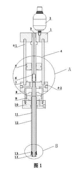
[0014] Fig. 1 is a structural schematic diagram according to one embodiment of
the
present invention.
[0015] Fig. 2 is an enlarged view of part A in Fig. 1.
[0016] Fig. 3 is an enlarged view of part B in Fig. 1.
[0017] In the figures, 1, rear end cover; 2, accumulator; 3, hydraulic
adjusting tube; 4,
pressure cylinder; 5, annular piston; 6, hydraulic valve body; 6-1, cone area;
7, middle
connecting body; 7-1, high pressure fluid inlet flow passage; 7-2, oil inlet
and outlet
port; 8, hydraulic propulsion cylinder; 9, propulsion piston; 10, front end
cover; 11,
injection gun tube; 11-1, groove; 12, sealing tube; 13, expansion rubber tube;
14,
thickened end portion.
DETAILED DESCRIPTION OF THE INVENTION
[0018] In order to make the purposes, technical solutions and advantages of
the
embodiments of the present invention clearer, the technical solutions in the
embodiments of the present invention will be clearly and completely described
below
with reference to the accompanying drawings in the embodiments of the present
invention. It is apparent that the described embodiments are a part of the
embodiments
of the present invention, and not all embodiments. All other embodiments
obtained by
a person of ordinary skill in the art based on the embodiments in the present
invention
without creative efforts fall within the scope of protection of the present
invention.
[0019] For the sake of clarity of description, it is specifically stated that
a 'front" end,
a 'front" half portion or a 'front" side mentioned in the present embodiment
refers to
4
Date Recue/Date Received 2020-05-06
CA 03081867 2020-05-06
a downward direction in Fig. 1, and -rear" is in line with an '`upward"
direction.
[0020] In the embodiment shown in Fig. 1 to Fig. 3, a hydraulic accumulator-
based
controllable pressure injection device for applying a cracking force in a rock
borehole
to break rock from the inside of the hole includes a pressure storage system,
a
pressure maintaining system, a sealing system, and an injection system, where
the
pressure storage system includes a pressure cylinder front half portion 4-2,
an annular
piston 5 and a middle connecting body 7, which are mounted on the same axis,
the
annular piston 5 is located between a pressure cylinder 4 and a hydraulic
adjusting
tube 3 and dynamically sealed, the pressure cylinder front half portion 4-2 is
fixedly
connected to an end portion of the middle connecting body 7, a high pressure
fluid
inlet flow passage 7-1 having both ends respectively communicating with the
outside
and an inner chamber of the pressure cylinder front half portion 4-2 is
provided in the
middle connecting body 7, a high pressure fluid medium enters the pressure
cylinder 4
through the high pressure fluid inlet flow passage 7-1, and the annular piston
5 is
pushed to move backwards to store the high pressure fluid medium; the pressure
maintaining system includes an accumulator 2, a pressure cylinder rear half
portion
4-1 and a rear end cover 1, the pressure cylinder rear half portion 4-1 and a
rear end of
the hydraulic adjusting tube 3 are detachably connected to the rear end cover
1,
respectively, and sealed, an outer end of the rear end cover 1 is provided
with the
accumulator 2, and the accumulator 2 is communicated to an inner chamber of
the
pressure cylinder rear half portion 4-1; the accumulator 2 absorbs high
pressure oil
from the pressure cylinder 4, when the high pressure fluid medium at a front
end of
the annular piston 5 is injected, the accumulator 2 releases stored hydraulic
oil to
maintain the pressure of the pressure cylinder 4 not to drop drastically
within a short
time; and as the pressure in the pressure cylinder 4 rises to a set pressure,
an oil
pressure in the hydraulic adjusting tube 3 is reduced, the hydraulic valve
body 6
moves backwards under the pressure of the high pressure fluid medium, and the
high
pressure fluid medium is injected from an injection gun tube 11. The sealing
system
includes a hydraulic propulsion cylinder 8, a propulsion piston 9, a front end
cover 10,
a sealing tube 12, a thickened end portion 14, and an expansion rubber tube
13, the
sealing tube 12 sequentially penetrates through the axes of the front end
cover 10 and
the propulsion piston 9, a rear end of the sealing tube 12 and the propulsion
piston 9
are fixedly connected into a whole, the expansion rubber tube 13 and a front
end of
Date Recue/Date Received 2020-05-06
CA 03081867 2020-05-06
the sealing tube 12 are butted and coaxially connected, the sealing tube 12
and the
front end cover 10 are dynamically sealed, the propulsion piston 9 and the
hydraulic
propulsion cylinder 8 are dynamically sealed, the expansion rubber tube 13 can
move
along the axis with the propulsion piston 9, a front end of the hydraulic
propulsion
cylinder 8 is detachably connected to a rear end of the front end cover 10 and
sealed, a
rear end of the hydraulic propulsion cylinder 8 is fixedly connected to the
middle
connecting body 7 by welding or the like, an oil inlet and outlet port 7-2
having both
ends respectively communicating with the outside and an inner chamber of the
hydraulic propulsion cylinder 8 is also provided in the middle connecting body
7, and
a backward pressure from the high pressure fluid medium at the front end
presses the
hydraulic oil into the accumulator through the annular piston 5 for storing
the pressure
in the system. The injection system includes a hydraulic valve body 6 and an
injection
gun tube 11, the hydraulic valve body 6 is coaxially mounted inside the
hydraulic
adjusting tube 3 in the pressure storage system and the two are dynamically
sealed at
front ends, and finally, the hydraulic valve body 6 can only be translated in
a groove
at the front end of the hydraulic adjusting tube 3, and cannot be moved out;
and the
injection gun tube 11 is coaxially sleeved inside the sealing tube 12 and
penetrates
through the propulsion piston 9, the thickened end portion 14 is coaxially and
detachably connected to a front end of the injection gun tube 11, a rear end
of the
injection gun tube 11 is fixedly connected to the middle connecting body 7 by
welding or the like, and the front end of the hydraulic valve body 6 has a
cone area
6-1 fitting a groove 11-1 at a rear end of the injection gun tube 11. The
hydraulic
valve body 6 is used to open and close a communication state between the
pressure
cylinder 4 and the injection gun tube 11, and the start and stop control of
the injection
system is realized by the hydraulic adjusting tube 3. Preferably, the cone
area 6-1 at
the front end of the hydraulic valve body 6 fits the groove 11-1 at the rear
end of the
injection gun tube 11, but there is still a part of the cone area exposed to a
high
pressure fluid, and a backward thrust is generated for the hydraulic valve
body 6. The
annular piston 5 is dynamically sealed with the pressure cylinder 4 and the
hydraulic
adjusting tube 3 through a guide strip and a Glyd ring, respectively, so that
the annular
piston 5 is slidable between the hydraulic adjusting tube 3 and the pressure
cylinder 4.
[0021] In the present embodiment, the pressure cylinder front half portion 4-2
and the
end portion of the middle connecting body 7 are welded together. The pressure
6
Date Regue/Date Received 2020-05-06
CA 03081867 2020-05-06
cylinder rear half portion 4-1 and the rear end cover 1 are connected by
threads, and
an 0 ring is provided therebetween for sealing. The hydraulic propulsion
cylinder 8 is
connected to the rear end of the front end cover 10 by threads, and an 0 ring
is
provided therebetween to ensure sealing of hydraulic oil. A guide strip and a
step seal
are provided between the front end cover 10 and the sealing tube 12 to ensure
sealing
of the hydraulic oil. The thickened end portion 14 is connected to the
injection gun
tube 11 by threads, and the hydraulic valve body 6 and the hydraulic adjusting
tube 3
are dynamically sealed through a guide sleeve and a Glyd ring, so that the
hydraulic
valve body 6 is pushed by hydraulic oil in the tube to move forwards, and the
cone
area 6-1 at the front end of the hydraulic valve body 6 fits the groove 11-1
at the rear
end of the injection gun tube 11 to form a sealed space in the pressure
cylinder 4.
[0022] In order to buffer the annular piston 5, a raised circular ring is
provided on an
end face of the middle connecting body 7 facing the pressure cylinder 4, the
raised
circular ring is located in an inner chamber of the pressure cylinder 4, and
the height
of the raised circular ring can be 1 cm.
[0023] Preferably, the groove 11-1 at the rear end of the injection gun tube
11 and the
cone area 6-1 at the front end of the hydraulic valve body 6 are both chamfers
of 45
degrees. Furthermore, the groove 11-1 is a 1x1 mm chamfer, and the cone area
(6-1)
is an 8x8 mm chamfer.
[0024] A hydraulic accumulator-based controllable pressure injection method
according to an embodiment of the present invention includes the following
steps:
[0025] a, inserting an injection gun tube 11 into a rock borehole, pushing, by
a
propulsion piston 9, a sealing tube 12 to push an expansion rubber tube 13 to
a
thickened end portion 14 such that an outer diameter of the injection gun tube
11 is
enlarged to fit an inner wall of the rock borehole to form a sealed space at
the bottom
of the rock borehole;
[0026] b, starting a hydraulic valve body 6 to fit a groove 11-1 at a rear end
of the
injection gun tube 11, and feeding a high pressure fluid medium via a high
pressure
fluid inlet flow passage 7-1 to form a high pressure area in a front section
of a
pressure cylinder 4;
[0027] c, monitoring pressure changes of the pressure cylinder 4 and an
accumulator 2;
and
7
Date Recue/Date Received 2020-05-06
CA 03081867 2020-05-06
[0028] d, after a pressure reaches a predetermined value, reducing the
pressure in a
hydraulic adjusting tube 3 to 0 gradually, when a pressure generated by the
high
pressure area against a cone area 6-1 at a front end of the hydraulic valve
body 6 is
greater than an oil path pressure in the hydraulic adjusting tube 3 at a rear
end,
allowing the hydraulic valve body 6 to slide backwards to be separated from
the
groove 11-1 at the rear end of the injection gun tube, and allowing the high
pressure
fluid medium to instantaneously surge into the sealed space at the bottom of
the rock
borehole under own pressure and the thrust of an annular piston 5, where the
pressure
generated is sufficient to cause the rock to break from the inside.
[0029] The high pressure fluid medium may be high pressure foam or high
pressure
water.
100301 The controllable pressure injection of the device is characterized in
that the
hydraulic adjusting tube 3 is supplied with oil by a controllable hydraulic
pumping
station, and the magnitude of a pressure for injecting a fluid medium is
controlled by
setting different oil supplies.
[0031] The above is only a preferred embodiment of the present invention, and
is not
intended to limit the present invention in any form. Any simple modifications
and
equivalent changes made to the above embodiments in accordance with the
technical
essence of the present invention fall into the scope of protection of the
present
invention.
8
Date Recue/Date Received 2020-05-06