Note: Descriptions are shown in the official language in which they were submitted.
CA 03082292 2020-05-11
PCT/EP2018/079121 - 1 -
2017P22820W0US
Description
Transformer for fastening to a mast of an energy distribution
network
The invention relates to a transformer for mounting on a mast of
an energy distribution network.
A transformer of this type is known, for example, from
W02001/08175 Al. The transformer disclosed therein is provided
for mounting on a mast of an air-insulated energy distribution
network and, in consequence, can also be described as a mast
transformer. The mast transformer disclosed herein comprises a
higher-voltage winding and lower-voltage windings, which are
arranged in an electrically insulating resin block in the form
of an insulating body. A bushing is formed on the solid resin
block which, at the end thereof which is averted from the resin
block, incorporates an overhead line terminal, the function of
which is to connect to an air-insulated phase conductor of the
energy distribution network. The higher- and lower-voltage
windings are inductively coupled to one another by means of an
iron core which is arranged externally to the resin block, such
that the desired voltage transformation is permitted. In order
to prevent voltage spikes in the resin block, insofar as
possible, a grounded shielding is provided in the form of a metal
cage, which entirely encloses the higher-voltage winding.
The known mast transformer is handicapped by a disadvantage, in
that the resin block and the core do not constitute a stable and
secure unit.
The object of the invention is therefore the provision of a
transformer of the abovementioned type, the core of which is
protected against environmental influences and corrosion and
wherein, simultaneously, a secure retention of the core and the
resin block is provided.
Date Recue/Date Received 2020-05-11
86326277
- 2 -
According to one aspect of the present invention, there is
provided a transformer for mounting on a mast of an energy
distribution network, having: a winding block which comprises a
solid insulating body, in which at least one higher-voltage
winding and at least one lower-voltage winding are arranged,
wherein the winding block delimits an entirely peripherally
closed central retention opening, a core unit which comprises at
least one magnetizable core and is inductively coupled to each
lower-voltage winding by means of each higher-voltage winding,
wherein the core unit extends through the retention opening by
means of at least one core limb and annularly encloses the
winding block on the exterior by means of a ring portion and
wherein at least one core of the core unit comprises a winding
core, and retaining means for fastening the ring portion to the
mast.
According to the invention, a winding block having a solid
insulating body is provided, in which the higher- and lower-
voltage windings are arranged. This winding block constitutes a
retention opening. The core unit is arranged externally to the
insulating body and thus, according to the invention, extends
through said retention opening.
The arrangement of the core unit externally to the insulating
body is advantageous in that, during the operation of the
transformer, magnetic fields are preferably directed within the
interior of the core unit. Although the core unit is preferably
comprised of mutually adjoining magnetizable electrical steel
sheets or strips, eddy currents occur during operation which are
responsible for the heat-up of the core unit. The associated
geometrical expansion of the core unit is dependent upon the
magnitude of the magnetic field and the coefficients of thermal
expansion of the core material employed. As the core unit is
arranged externally to the insulating body, any cracks in the
Date recue/date received 2021-10-21
86326277
- 2a -
insulating body associated with a differential thermal expansion
of the core and the insulating body are prevented.
As the core unit extends through the retention opening, it is
sufficient, according to the invention, that the retaining means
Date recue/date received 2021-10-21
CA 03082292 2020-05-11
PCT/EP2018/079121 - 3 -
2017P22820WOUS
are employed solely for the fastening of the annular ring portion
of the core unit. The winding block is supported in this case by
the core limb which extends through the retention opening. The
retention system according to the invention is consequently
simple, and thus cost-effective. Moreover, a rapid fitting of
the transformer to the mast is made possible, wherein the
fastening means moreover provide protection for the core unit,
which is sensitive to environmental influences.
Appropriately, the section of the core unit which projects
through the retention opening, with respect to its outer contour,
is adapted to the inner contour of the retention opening. In
other words, the external diameter of said core unit section is
somewhat smaller than the internal diameter of the retention
opening, such that a mechanically stable unit is provided.
Naturally, in the context of the invention, it is possible that,
between the core unit section which extends through the retention
opening and the insulating body in this region, holding or
insulating materials are arranged for the improvement of
mechanical retention and the prevention of vibrations.
The core unit comprises at least one core which is configured,
for example, in the form of a "wound core". Thus, for example,
each core comprises "core winding layers", which are led through
the retention opening. However, wound cores and materials of
this type are already highly familiar to a person skilled in the
art, such that any further description thereof can be omitted at
this point.
The core unit can comprise only one core having a central core
limb, which extends through the retention opening, and two return
limbs which, in combination with the yoke, constitute the ring
portion. By way of deviation, a plurality of cores can be
provided, each of which constitutes a closed iron core circuit
or magnetic circuit per se.
Date Recue/Date Received 2020-05-11
CA 03082292 2020-05-11
PCT/EP2018/079121 - 4 -
2017P22820WOUS
Advantageously, the core unit is impregnated with a curable
polymer. As described above, the core is exposed to environmental
influences, and is preferably comprised of a ferromagnetic
material, in particular an electrical steel sheet or strip which
is configured, for example, as a grain-oriented electrical sheet
steel. The overall thickness of the material which is wound to
constitute a loop of the coil lies, for example, between 0.1 mm
and 0.5 mm. Soft magnetic materials must be protected against
corrosion, such that the magnetic induction effect of the core
is not compromised. For this reason, a polymer is provided, which
is introduced into the core unit in a liquid state. The core
unit is impregnated with the liquid. Thereafter, the polymer is
cured by the action of heat, for example in a kiln, and preferably
in a vacuum kiln. The vacuum thus draws the still liquid polymer
into all the interspaces which would otherwise be exposed to
environmental influences such that, further to the complete
polymerization of the polymer, effective protection for the core
unit is provided. The polymer is, for example, a standard
proprietary resin, or a polymer which is otherwise employed in
the field of transformer construction. The polymer can
incorporate customary admixtures.
According to a further configuration of the invention, the
retaining means incorporate a supporting frame which is
configured such that it entirely encloses the external ring
portion of the transformer. In other words, the supporting frame
provides secure protection against moisture and harmful
environmental influences, such that the action of the
impregnation which is optionally provided is reinforced by the
supporting frame. In principle, the supporting frame can be
configured in an arbitrary manner, provided that it ensures the
complete encapsulation of the ring portion.
According to a preferred variant of the invention, however, the
supporting frame comprises a closed peripheral sidewall with a
Date Recue/Date Received 2020-05-11
CA 03082292 2020-05-11
PCT/EP2018/079121 - 5 -
2017P22820WOUS
C-shaped cross-section, which entirely encloses the ring
portion. The ring portion runs around the exterior of the winding
block in an annular manner or, in other words, in a ring shape,
such that the latter can be arranged within the C-shaped
supporting frame. Naturally, with respect to its dimensioning,
the supporting frame is adapted to the ring portion, such that
the complete enclosure of said ring portion is possible.
According to an appropriate further development with respect
hereto, an insulating material is arranged between the supporting
frame and the ring portion. The insulating material is
responsible, for example, for noise reduction, and for the
additional protection of the ring portion. An appropriate
insulating material is, for example, an appropriate glass-fiber
fabric which, in addition to its protective and noise reduction
action, also permits sufficient cooling of the ring portion,
which undergoes heat-up in service.
Advantageously, the core unit comprises two cores, each of which
extends with one core limb through the retention opening, and
each of which encloses one limb of the winding body over its
full periphery. The cores are advantageously wound from an
electrical steel strip, as described above.
Appropriately, between the core limbs of the cores which extend
through the retention opening, at least one intermediate layer
is arranged, which delimits cooling ducts. In this manner,
adequate cooling of the cores is ensured, given that said cores
undergo heat-up during operation and it is necessary for the
heat thus generated to be evacuated.
Advantageously, intermediate layers are arranged between the
winding block and the core unit, which delimit cooling ducts.
According to this advantageous further development, intermediate
layers are also arranged between the solid retention block and
the core unit. Intermediate layers of a flexible material are
Date Recue/Date Received 2020-05-11
CA 03082292 2020-05-11
PCT/EP2018/079121 - 6 -
2017P22820WOUS
conceivable, which form recesses by means of which the cooling
ducts are constituted.
Advantageously, the retaining means incorporate a fastening rail
for fitting to the mast, which is detachably connectable to the
supporting frame by means of a form-fitted connection. A form-
fitted connection of this type is, for example, a simple hook
connection, which appropriately incorporates a retaining plate,
in which a hook which is configured on the supporting frame can
be suspended. However, the hook can also be configured on the
fastening rail, wherein the hook comprises an upwardly extending
free end, over which a retaining bracket of the supporting frame
can be fitted.
Further advantages are conferred if a base structure for the
retention of the winding block is provided, which is fastened to
the supporting frame. The base structure is, for example,
configured in the form of two retaining brackets, each of which
is fitted on one side of the supporting frame and delimits a
basket-shaped inner contour, which is configured with a matching
shape to the outer contour of the winding block. In other words,
the retaining brackets are configured such that the winding block
can be supported on the latter.
However, the base structure can also be configured in any other
manner and can also be configured with additional insulating
material.
It is further appropriate that the supporting frame and/or the
base structure is/are equipped with a grounding nut. The
grounding nut permits, in a simple manner, the grounding of the
shielding of the higher-voltage winding which is arranged in the
retention block. Moreover, it is also possible for the
transformer according to the invention to be connected in
parallel with a "surge arrester". The surge arrester is connected
by means of the retaining nut.
Date Recue/Date Received 2020-05-11
CA 03082292 2020-05-11
PCT/EP2018/079121 - 7 -
2017P22820WOUS
Further appropriate configurations and advantages of the
invention are the subject matter of the following description of
exemplary embodiments of the invention, with reference to the
figures in the drawing, wherein identically functioning
components are identified by the same reference numbers, and
wherein:
Figure 1 illustrates a first exemplary embodiment of the
transformer according to the invention, in a
schematic sectional side view,
Figure 2 illustrates the transformer according to figure 1, in
a mounted position on a mast, and
Figure 3 illustrates a further exemplary embodiment of the
transformer according to the invention.
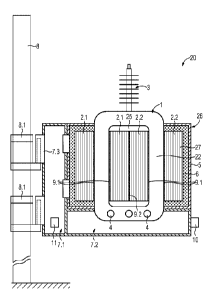
Figure 1 shows an exemplary embodiment of the transformer 20
according to the invention in a schematic sectional side view.
The transformer 20 incorporates a winding body 1, which comprises
one or two solid and dry insulating bodies of cast resin,
together with two lower-voltage windings and a higher-voltage
winding. Said windings are not diagrammatically represented. The
higher-voltage winding is arranged between the lower-voltage
windings. The higher-voltage winding is further enclosed by a
shielding which, likewise, is not diagrammatically represented.
A bushing 3 is formed on the winding body 1, which extends from
the winding body 1 to a free end, at which an overhead line
terminal 30 is constituted. A further correspondingly configured
bushing is arranged directly behind the bushing 3, in the viewing
direction, and is thus not visible in figure 1. Moreover, the
insulating ribs of the bushing 3 are schematically represented.
An inner conductor, which is not diagrammatically represented,
extends through the bushing 3, and connects the overhead line
Date Recue/Date Received 2020-05-11
CA 03082292 2020-05-11
PCT/EP2018/079121 - 8 -
2017P22820WOUS
terminal 30 to the higher-voltage winding of the winding body 1.
In the lower winding body section 23, low-voltage terminals 4
are configured, which are respectively connected to the two
lower-voltage windings.
The winding body 1 constitutes two winding body limbs 21 and 22,
which are interconnected by means of a lower 23 and an upper 24
winding body section. The winding body limbs 21, 22 and the upper
and lower winding body sections 23, 24 thus delimit a retention
opening 25, through which a core unit 26 projects. The core unit
26 comprises a first core 2.1 and a second core 2.2, each of
which encloses a winding body limb 21 or 22 over the full
periphery thereof. Each core 2.1, 2.2 is a "wound core", wherein
each core is comprised of a plurality of winding strips or
electrical steel strips, which are arranged adjacently to one
another. The electrical steel strips or electrical steel sheets
are comprised of grain-oriented electrical sheet steel, or of an
amorphous material. However, wound cores of this type will be
familiar to a person skilled in the art, such that it is not
necessary to address the latter in any greater detail at this
point.
Each of the two cores 2.1 and 2.2 respectively comprises a limb,
by means of which the respective core 2.1 or 2.2 extends through
the retention opening 25. Externally to the retention opening
25, the core unit 26 extends around the winding body 1 in an
annular manner at a ring portion 27.
For corrosion protection, the cores 2.1, 2.2, and specifically
both the ring portion 27 and the limb which extends through the
retention opening 25 have been impregnated with a polymer, in
this case a resin. The resin has been applied to the core in a
liquid state in a vacuum kiln such that, on the grounds of the
vacuum, the liquid resin penetrates all the interspaces of the
respective core 2.1, 2.2. Thereafter, the resin is cured by the
heat of the kiln, such that the electrical steel strips or the
Date Recue/Date Received 2020-05-11
CA 03082292 2020-05-11
PCT/EP2018/079121 - 9 -
2017P22820WOUS
electrical steel sheets of the cores 2.1 and 2.2 are impregnated
with resin. In this manner, effective corrosion protection is
provided.
For the enhancement of corrosion protection, but also for the
fastening of the transformer 20, a supporting frame 5 is
provided, which comprises C-shaped sidewalls which enclose the
ring portion 27 of the core unit 26 over the full periphery
thereof. In other words, the ring portion 27 is entirely arranged
within the supporting frame 5. Between the supporting frame 5
and the ring portion 27, a corrosion-protection and an insulating
material 6 is inserted, the function of which, firstly, is the
provision of the requisite corrosion protection, and secondly
the damping of noise associated with the operation of the
transformer. As a corrosion-protection and insulating material
6, for example, an appropriate glass-fiber material is
conceivable.
On the supporting frame 5, a grounding nut 10, which is screwed
onto a stud of the supporting frame 5 which is provided with an
external thread, is discernible, wherein said stud is connected
to the abovementioned shielding. The grounding nut 10 permits a
simple grounding of the shielding, but also the connection of
the transformer to a surge arrester, such that the desired
overvoltage protection of the transformer is provided.
Between the winding body limbs 21 and the respective section of
the core 2.1 or 2.2, intermediate layers 9.1 are arranged, which
are comprised of an elastomer and which constitute cooling ducts,
which are delimited from the intermediate layer 9.1 to the
respective limb 21 or 22, and to the respective core section. An
intermediate layer 9.2 between the cores 2.1 and 2.2 also
executes a delimiting function for the cooling ducts, wherein
the intermediate layers are elastically configured and also
assume a noise-reducing function.
Date Recue/Date Received 2020-05-11
CA 03082292 2020-05-11
PCT/EP2018/079121 - 10 -
2017P22820WOUS
Figure 2 illustrates the fastening of the transformer 20
according to figure 1 to a mast 8. To this end, the transformer
20 incorporates retaining means, which comprise a fastening rail
7.1 which is fastened to the mast 8 by means of two hook-shaped
mast brackets 8.1. In each case, the fastening rail 7.1
constitutes a mating element 7.3 for the hook-shaped mast
brackets 8.1, such that the fastening rail 7.1 can be rapidly
and simply hooked into the mast bracket 8.1. The fastening rail
7.1 is rigidly connected to the supporting frame 5.
In addition to the mast bracket 8.1, the fastening rail 7.1, the
mating element 7.3 and the supporting frame 5, the retaining
means comprise a base structure 7.2 which, in the exemplary
embodiment represented in figure 2, is rigidly connected to the
supporting frame 5 and supports the winding body 1 from below,
such that an additional stabilization of the transformer 1 is
ensured. In the exemplary embodiment represented, the fastening
rail 7.1 and the base structure 7.2 are configured as separate
components which are connected to one another in a detachable
manner.
For assembly, the winding body 1 is firstly produced, together
with the bushing 3. Thereafter, the cores 2.1 and 2.2 are fitted
around the winding body limbs 21 and 22, wherein the intermediate
layers 9.1 and 9.2 are inserted. Thereafter, the supporting frame
is fitted, together with the corrosion-protection and
insulating material 6. The fitting of the fastening rail 7.1 and
the base structure 7.2 is then executed. The final stage is
suspension in the mast bracket 8.1, which has previously been
secured to the mast 8. In order to simplify assembly, for example
with the aid of lifting vehicles such as cranes or similar,
suspension openings 11 are provided in the retaining means M.
Figure 3 shows a further exemplary embodiment of the transformer
20 according to the invention. The mast bracket 8.1 shown here
is equipped with an upper and a lower mast bracket 8.1, wherein
Date Recue/Date Received 2020-05-11
CA 03082292 2020-05-11
PCT/EP2018/079121 - 11 -
2017P22820WOUS
each mast bracket 8.1 constitutes only a single hook, in which
one mating element 7.3 can be suspended respectively. The mating
elements 7.3 are again arranged on the fastening rail 7.1 which,
on the side thereof which is averted from the mating element
7.3, is rigidly connected to a part of the supporting frame 5.
The fastening rail 7.1, conversely to the exemplary embodiment
represented in figure 2, is configured with an L-shape, and
comprises a perpendicular section, which extends parallel to the
mast, and a horizontal section, at which the fastening rail 7.1
engages with the winding body 1 from below. The fastening rail
7.1, at the side thereof which is averted from the mast 8, is
also connected in this case to another part of the supporting
frame 5, such that the winding body 1, the core unit 26 and the
retaining means 5, 7.1 and 7.3 constitute a stable unit. The two
said parts of the supporting frame 5 are screwed together. The
part of the supporting frame 5 which is averted from the mast 8,
in an overhead view of the transformer 20, is configured with a
C-shape and, at the ends of its free limb, is screwed to that
part of the supporting frame 5 which extends longitudinally in
one direction.
Lifting lugs 7.4 which are fastened to the supporting frame 5
simplify the installation of the transformer 20 on the mast 8 by
means of a lifting crane.
Date Recue/Date Received 2020-05-11