Note: Descriptions are shown in the official language in which they were submitted.
LOCKING DEVICE AND SYSTEM FOR TRUCK COVER
TECHNICAL FIELD
[0001] The present application relates to a pickup truck accessory,
and in particular,
to a locking structure and a pickup truck compai intent cover including the
locking
structure.
BACKGROUND
[0002] A pickup truck may include an open back compai _________
intent, which may be
configured to transport cargoes. When cargoes are transported in severe
weather, a
compartment cover is usually mounted at a top portion of the back compai __
intent to the
pickup truck to protect the transported cargoes. An existing compai intent
cover of a light
pickup truck may include a connection frame and a soft cover. The connection
frame is
formed by connecting a side frame to a corner joint. The side frame includes a
clamp slot.
Nylon clamping members matching the clamp slot are evenly distributed on the
periphery
inside the soft cover, to implement a match between the soft cover and the
connection
frame. The soft cover implements detachable mounting on the connection frame
through a
match between the nylon clamping members and the clamp slot of the side frame.
However, the foregoing detachable mounting structure results in complex
opening and
closing of the soft cover on the connection frame.
SUMMARY
[0003] An objective of the present application is to provide a
locking structure. A
locking manner and an unlocking manner of the locking structure are both
simple.
[0004] The present application provides a locking structure. The
locking structure
includes two fixing side frames and a locking frame. A locking slot is
disposed on an inner
side wall of the fixing side frame. The locking frame is movably mounted at
end portions of
1
Date Recue/Date Received 2020-06-08
the two fixing side frames, locking cartridge assemblies corresponding to the
fixing side
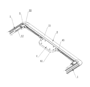
frames are respectively disposed at both ends of the locking frame, and the
locking frame is
further provided, between the locking cartridge assemblies, with a sliding
cartridge
assembly controlling the two locking cartridge assemblies to synchronously
open. The
locking cartridge assembly comprises a locking cartridge, a locking member,
and at least
one locking spring, wherein the locking member is slidably mounted in the
locking
cartridge along a longitudinal direction of the locking frame, the locking
member comprises
a lock tongue inserted into the locking slot, one end of the at least one
locking spring abuts
against the locking cartridge, and the other end abuts against the locking
member. The
sliding cartridge assembly comprises a control cartridge, a sliding handle,
and an inhaul
cable member, wherein the sliding handle is slidably mounted in the control
cartridge along
a direction perpendicular to the longitudinal direction of the locking frame,
two ends of the
inhaul cable member are respectively connected to the locking members of the
two locking
cartridge assemblies, and the inhaul cable member abuts against the sliding
handle. When
the locking frame is mounted at the end portions of the two fixing side
frames, the at least
one locking spring can push the lock tongue to be clamped into the locking
slot, and the
sliding handle can drive the inhaul cable member to make the lock tongue break
away from
the locking slot.
[0005] The above objective of the present application can be achieved
by the
following technical solutions:
[0006] A locking structure includes two fixing side frames and a
locking frame. The
locking frame may include a locking horizontal frame. A locking slot is
disposed on an
inner side wall of the fixing side frame. The locking horizontal frame is
movably mounted
at end portions of the two fixing side frames. Locking cartridge assemblies
corresponding
to the fixing side frames are respectively disposed at both ends of the
locking horizontal
frame. The locking horizontal frame is further provided, between the locking
cartridge
assemblies, with a sliding cartridge assembly controlling the two locking
cartridge
assemblies to synchronously open. The locking cartridge assembly includes a
locking
cartridge, a locking member, and a locking spring. The locking member is
slidably mounted
2
Date Recue/Date Received 2020-06-08
in the locking cartridge along a length direction of the locking horizontal
frame. The
locking member includes a lock tongue inserted into the locking slot. One end
of the
locking spring abuts against the locking cartridge and the other end abuts
against the
locking member. The sliding cartridge assembly includes a control cartridge, a
sliding
handle, and an inhaul cable member. The sliding handle is slidably mounted in
the control
cartridge along a direction perpendicular to the locking horizontal frame. Two
ends of the
inhaul cable member are respectively connected to the locking members of the
two locking
cartridge assemblies. The inhaul cable member abuts against the sliding
handle. When the
locking horizontal frame is mounted at the end portions of the two fixing side
frames, the
locking spring enables the lock tongue to always have a trend to be clamped
into the
locking slot, and the sliding handle can drive the inhaul cable member to make
the lock
tongue break away from the locking slot.
[0007] By using the foregoing technical solution, when the locking
horizontal frame
is mounted on the end portions of the fixing side frames, the lock tongue of
the locking
member in the locking cartridge assembly at either end of the locking
horizontal frame is
inserted into the locking slot of the fixing side frame under the effect of
the locking spring,
to lock the locking structure. When the locking structure is unlocked, only
the sliding
handle of the sliding cartridge assembly needs to be slided. Under driving of
the sliding
handle, the inhaul cable member may overcome an elasticity of the locking
spring to make
the lock tongue of the locking member break away from the locking slot, and
then the
locking horizontal frame is taken out of the fixing side frames. A locking
operation and an
unlocking operation of the locking structure are both convenient, helping to
implement
quick locking and unlocking of the pickup truck compai intent cover.
[0008] In a preferred embodiment, the locking cartridge is provided
with a locking
sliding slot and a locking cover plate covering the locking sliding slot. The
locking member
further includes a locking sliding plate matching the locking sliding slot.
The locking
cartridge is further provided with a first opening for the lock tongue to
extend and a second
opening for ease of connection between the inhaul cable member and the locking
member.
By using the foregoing technical solution, the match between the locking
sliding plate and
3
Date Recue/Date Received 2020-06-08
the locking sliding slot can guide the sliding of the locking member, so that
the stability of
the sliding of the locking member is improved and the probability that the
lock tongue of
the locking member cannot be normally inserted into the locking slot or the
lock tongue of
the locking member cannot be normally break away from the locking slot is
reduced.
[0009] In a preferred embodiment, the lock tongue is connected to a
middle portion
of the locking sliding plate, the locking sliding plate is provided with two
spring slots that
are symmetrically disposed at a side surface back to the lock tongue, and the
number of the
locking springs in each of the locking cartridge assemblies is two and the two
locking
springs are respectively mounted in the corresponding spring slot.
[0010] By using the foregoing technical solution, the two locking
springs
respectively abut against the two spring slots of the locking sliding plate,
so that the
stability of the sliding of the locking member can be further improved and the
probability
that the lock tongue of the locking member cannot be normally inserted into
the locking
slot or the lock tongue of the locking member cannot be normally break away
from the
locking slot is reduced.
[0011] In a preferred embodiment, the locking member further includes
a pulling
rod extending out of the locking cartridge from the second opening, and the
pulling rod is
provided with a mounting hole for mounting the inhaul cable member.
[0012] The foregoing technical solution is a manner of mounting the
locking
member and the inhaul cable member. The mounting manner is simple in structure
and
mounting is convenient.
[0013] In a preferred embodiment, a clamp column is disposed at
either end of the
inhaul cable member, and the locking member is provided with a clamp hole for
inserting
the clamp column and a clamp slot for the inhaul cable member to extend out of
the clamp
hole.
[0014] The foregoing technical solution is another manner of mounting
the locking
member and the inhaul cable member. The inhaul cable member implements
mounting with
the locking member through the match between the clamp column and the clamp
hole. The
4
Date Recue/Date Received 2020-06-08
mounting manner is high in structural strength, the mounting structure is
simple, and the
mounting is convenient.
[0015] In a preferred embodiment, the locking member is provided with
a mounting
slot on a side surface facing a bottom surface of the locking sliding slot,
the locking
cartridge is provided, on the bottom surface of the locking sliding slot, with
an abutment
plate inserted into the mounting slot, the locking spring is mounted in the
mounting slot,
and one end of the locking spring abuts against the abutment plate and the
other end abuts
against an inner side wall close to the lock tongue in the mounting slot.
[0016] By using the foregoing technical solution, the locking spring
is mounted in
the mounting slot of the locking member, so that the stability of the sliding
of the locking
member is improved and the probability that the lock tongue of the locking
member cannot
be normally inserted into the locking slot or the lock tongue of the locking
member cannot
be normally break away from the locking slot is reduced.
[0017] In a preferred embodiment, the control cartridge includes a
bottom cartridge
and a cartridge cover, a control sliding slot for a control handle to slide is
disposed on a
bottom surface of the bottom cartridge, the inhaul cable member runs through a
left side
surface and a right side surface of the control cartridge and abuts against a
side on which
the control handle faces the locking horizontal frame; the control handle is
provided with a
handheld slot on a side back to the control sliding slot, and the cartridge
cover is provided
with a handle opening corresponding to the handheld slot.
[0018] By using the foregoing technical solution, the control handle
is slidably
mounted in an inner cavity of the control cartridge and abuts against the
inhaul cable
member in the inner cavity of the control cartridge, so that the control
handle applies a
force to the inhaul cable member more stably. In addition, setting of the
handle opening and
a handle slot can make it convenient for a hand of an operator to pass through
the handle
opening and insert into the handle slot, and make it convenient for the
operator to slide the
control handle.
Date Recue/Date Received 2020-06-08
[0019] In a preferred embodiment, the locking horizontal frame is
mounted with a
guide member on two sides of the control cartridge, and the guide member is
provided with
a guide hole for the inhaul cable member to run through.
[0020] By using the foregoing technical solution, the guide member
can guide and
support expansion of the inhaul cable member, helping to reduce probability of
interference
between the inhaul cable member and the locking horizontal frame.
[0021] In a preferred embodiment, the fixing side frame is further
provided with a
positioning seat, where the positioning seat includes a positioning clamp
slot; a positioning
protrusion matching the positioning clamp slot is disposed at either end of
the locking
horizontal frame, and a positioning end surface is further disposed at either
end of the
locking horizontal frame; and when the positioning protrusion is clamped into
the
corresponding positioning clamp slot, the positioning end surface is attached
with to end
surface of the fixing side frame.
[0022] By using the foregoing technical solution, the locking
horizontal frame
implements detachable mounting with the fixing side frames by disposing the
positioning
protrusion and the positioning end surface. The mounting manner is simple in
structure and
demounting is convenient.
[0023] Another objective of the present application is to provide a
pickup truck
compartment cover. The locking and unlocking of the pickup truck compai ___
intent cover on
the pickup truck are convenient.
[0024] The foregoing technical objective of the present application
can be achieved
through the following technical solution:
[0025] A pickup truck compartment cover includes a fixing horizontal
frame and a
soft cover. The pickup truck compaitment cover further includes the foregoing
locking
structure. The fixing horizontal frame and fixing side frames are all mounted
in the
compartment of the pickup truck. One end of the soft cover is mounted on the
fixing
horizontal frame and the other end is mounted on the locking horizontal frame,
and two
sides of the soft cover respectively detachably match the fixing side frames.
6
Date Recue/Date Received 2020-06-08
[0026] In summary, the present application may achieve the following
beneficial
effects.
1. A locking structure includes two fixing side frames and a locking
horizontal
frame. The locking horizontal frame is detachably mounted at end portions of
the two
fixing side frames. Locking cartridge assemblies matching a locking slot of
the fixing side
frames are respectively disposed at both ends of the locking horizontal frame,
and a sliding
cartridge assembly controlling the two locking cartridge assemblies to
synchronously open
is further disposed at either end of the locking horizontal frame, thereby
implementing
rapid locking and rapid unlocking of the locking structure.
2. The match between the locking sliding plate of the locking member and the
locking sliding slot of the locking cartridge can improve the stability of the
sliding of the
locking member and reduce the probability that the lock tongue of the locking
member
cannot be normally inserted into the locking slot or the lock tongue of the
locking member
cannot be normally break away from the locking slot.
3. A pickup truck compatiment cover, including a fixing horizontal frame, a
soft
cover and the foregoing locking structure. Rapid locking and rapid unlocking
of the fixing
side frames and the locking horizontal frame in the locking structure make
opening and
closing of the soft cover convenient.
BRIEF DESCRIPTION OF THE DRAWINGS
[0027] FIG. 1 is a schematic structural diagram of a locking
structure according to
Embodiment 1;
[0028] FIG. 2 is a schematic structural diagram of fixing side frames
according to
Embodiment 1;
[0029] FIG. 3 is a schematic structural diagram of locking cartridge
assemblies in
an explosive state according to Embodiment 1;
7
Date Recue/Date Received 2020-06-08
[0030] FIG. 4 is a schematic structural diagram of a locking member
according to
Embodiment 1;
[0031] FIG. 5 is a schematic structural diagram of a sliding
cartridge assembly in an
explosive state according to Embodiment 1;
[0032] FIG. 6 is an enlarged view of a place A in FIG. 5;
[0033] FIG. 7 is an enlarged view of a place B in FIG. 5;
[0034] FIG. 8 is a schematic structural diagram of a bottom portion
of a sliding
handle according to Embodiment 1;
[0035] FIG. 9 is a schematic structural diagram of locking cartridge
assemblies in
an explosive state according to Embodiment 2;
[0036] FIG. 10 is a schematic structural diagram of a locking member
according to
Embodiment 2;
[0037] FIG. 11 is a schematic structural diagram of an end portion of
an inhaul
cable member according to Embodiment 3;
[0038] FIG. 12 is a schematic structural diagram of locking cartridge
assemblies in
an explosive state according to Embodiment 3;
[0039] FIG. 13 is a schematic structural diagram of a locking member
according to
Embodiment 3; and
[0040] FIG. 14 is a schematic structural diagram of a pickup truck
compaiiment
cover according to Embodiment 4.
[0041] The figures include:
1: Fixing side frame;
11: Locking slot;
12: Positioning seat;
13: Positioning clamp slot;
8
Date Recue/Date Received 2020-06-08
2: horizontal frame;
21: Horizontal frame body;
22: Corner joint;
221: Positioning protrusion;
222: Positioning end surface;
3: Locking cartridge assembly;
31: Locking cartridge;
311: Locking sliding slot;
312: Locking cover plate;
313: First opening;
314: Second opening;
315: Abutment plate;
32: Locking member;
321: Lock tongue;
322: Locking sliding plate;
3221: Spring slot;
323: Pulling rod;
3231: Mounting hole;
324: Mounting slot;
325: Clamp hole;
326: Clamp slot;
33: Locking spring;
4: Sliding cartridge assembly;
9
Date Recue/Date Received 2020-06-08
41: Control cartridge;
411: Bottom cartridge;
412: Cartridge cover;
4121: Handle opening;
413: Through-hole via;
414: Control sliding slot;
415: Guide column;
416: Guide seat;
4161: Guide slot;
42: Sliding handle;
421: Control sliding block;
422: Handheld slot;
43: Inhaul cable member;
431: Clamp column;
44: Guide member;
441: Guide hole;
5: Fixing horizontal frame;
6: Soft cover.
DETAILED DESCRIPTION
[0042] The present application will now be described in detail
hereinafter with
reference to the accompanied drawings, which form a part of the present
application, and
which show, by way of illustration, specific examples of embodiments. Please
note that the
present application may, however, be embodied in a variety of different forms
and,
Date Recue/Date Received 2020-06-08
therefore, the covered or claimed subject matter is intended to be construed
as not being
limited to any of the embodiments to be set forth below. Please also note that
the present
application may be embodied as methods, devices, components, or systems.
[0043] Throughout the specification and claims, terms may have nuanced
meanings
suggested or implied in context beyond an explicitly stated meaning. Likewise,
the phrase
"in one embodiment" or "in some embodiments" as used herein does not
necessarily refer
to the same embodiment and the phrase "in another embodiment" or "in other
embodiments" as used herein does not necessarily refer to a different
embodiment. It is
intended, for example, that claimed subject matter includes combinations of
exemplary
embodiments in whole or in part.
[0044] In general, terminology may be understood at least in part from
usage in
context. For example, terms, such as "and", "or", or "and/or," as used herein
may include a
variety of meanings that may depend at least in part upon the context in which
such terms
are used. Typically, "or" if used to associate a list, such as A, B or C, is
intended to mean
A, B, and C, here used in the inclusive sense, as well as A, B or C, here used
in the
exclusive sense. In addition, the term "one or more" or "at least one" as used
herein,
depending at least in part upon context, may be used to describe any feature,
structure, or
characteristic in a singular sense or may be used to describe combinations of
features,
structures or characteristics in a plural sense. Similarly, terms, such as
"a", "an", or "the",
again, may be understood to convey a singular usage or to convey a plural
usage,
depending at least in part upon context. In addition, the term "based on" or
"determined by"
may be understood as not necessarily intended to convey an exclusive set of
factors and
may, instead, allow for existence of additional factors not necessarily
expressly described,
again, depending at least in part on context.
[0045] The present application describes a few embodiments of a
locking structure
for a pickup truck.
Embodiment 1:
11
Date Recue/Date Received 2020-06-08
[0046] Referring to FIG. 1, a locking structure is applied to a
pickup truck
compartment cover and mainly includes two fixing side frames 1 and a locking
frame 2. In
one implementation, the locking frame 2 may include a locking horizontal frame
2.
[0047] The two fixing side frames 1 are disposed parallel to each
other, and the
locking horizontal frame 2 is perpendicular to the two fixing side frames 1
and is
detachably mounted at end portions of the two fixing side frames 1.
[0048] Referring to FIG. 2, a locking slot 11 is disposed on an inner
side wall of the
fixing side frame 1 along a length direction of the fixing side frame 1, and
the fixing side
frame 1 is mounted with a positioning seat 12 at an end that is of the inner
side wall of the
fixing side frame 1 and that is close to the locking horizontal frame 2. The
positioning
seat is directly fixed on the inner side wall of the fixing side frame 1 by
using a screw. The
positioning seat 12 is provided with a positioning clamp slot 13 on a side
facing the locking
horizontal frame 2.
[0049] Referring to FIG. 1, the locking horizontal frame 2 includes a
horizontal
frame body 21 and two corner joints 22 respectively mounted at two ends of the
horizontal
frame body 21. Each corner joint 22 is provided with a locking cartridge
assembly 3
disposed corresponding to the fixing side frame 1.
[0050] Referring to FIG. 1 and FIG. 3, the locking cartridge assembly
3 includes a
locking cartridge 31, a locking member 32, and two locking springs 33.
[0051] Referring to FIG. 1 and FIG. 3, the locking member 32 mainly
includes a
lock tongue 321, a locking sliding plate 322 and a pulling rod 323. The lock
tongue 321 can
be inserted into a locking slot 11 (referring to FIG. 2) of the fixing side
frame 1, thereby
implementing locking of the locking horizontal frame 2 and the fixing side
frame 1.
[0052] Referring to FIG. 4, the lock tongue 321 is vertically
connected to a middle
portion of the locking sliding plate 322. The pulling rod 323 is connected to
a middle
portion of a side surface that is of the locking sliding plate 322 and that is
back to the lock
tongue 321. The locking sliding plate 322 is left-right symmetrically provided
with two
spring slots 3221 on the side surface back to the lock tongue 321. A mounting
hole 3231 is
12
Date Recue/Date Received 2020-06-08
disposed at an end that is of the pulling rod 323 and that is away from the
locking sliding
plate 322.
[0053] Referring to FIG. 3, the locking cartridge 31 is provided with
a locking
sliding slot 311 and a locking cover plate 312 covering the locking sliding
slot 311. The
locking cover plate 312 is directly mounted on the locking cartridge 31 by
using a screw.
The locking member 32 is slidably mounted in the locking sliding slot 311 of
the locking
cartridge 31 along a longitudinal direction of the locking horizontal frame 2.
The locking
sliding plate 322 of the locking member 32 matches the locking sliding slot
311. The
longitudinal direction of the locking horizontal frame 2 may be a length
direction of the
locking horizontal frame.
[0054] The locking cartridge 31 is further provided with a first
opening 313 for the
lock tongue 321 to extend and a second opening 314 for the pulling rod 323 to
extend.
[0055] The locking spring 33 is mounted in the locking cartridge 31.
One end of the
locking spring 33 is inserted into the spring slot 3221 of the locking sliding
plate 322, and
the other end abuts against a side wall that is of the locking cartridge 31
and that is in the
locking sliding slot 311.
[0056] Referring to FIG. 1 to FIG. 3, the corner joint 22 is
provided, at an end that
is of the locking cartridge 31 and that faces the positioning seat 12, with a
positioning
protrusion 221 matching a positioning clamp slot 13. The corner joint 22 is
further provided
with a positioning end surface 222 attached to an end surface of the fixing
side frame 1.
[0057] When the locking horizontal frame 2 is mounted on the two
fixing side
frames 1, the positioning protrusion 221 on the corner joint 22 is clamped
into the
positioning clamp slot 13 of the positioning seat 12. The lock tongue 321 of
the locking
member 32 is clamped into the locking slot 11 of the fixing side frame 1 under
effect of the
locking spring 33. The positioning end surface is attached to the end surface
of the fixing
side frame 1.
13
Date Recue/Date Received 2020-06-08
[0058] Referring to FIG. 1, the middle portion of the locking
horizontal frame 2 is
further mounted with a sliding cartridge assembly 4 controlling the locking
cartridge
assemblies 3 to synchronously unlock.
[0059] Referring to FIG 1 and FIG. 5, the sliding cartridge assembly
4 includes a
control cartridge 41, a sliding handle 42, and an inhaul cable member 43.
[0060] Referring to FIG. 1, FIG. 5, and FIG. 6, the control cartridge
41 includes a
bottom cartridge 411 and a cartridge cover 412 covering an opening of the
bottom cartridge
411. The cartridge cover 412 is mounted on the bottom cartridge 411 by using a
screw. The
control cartridge 41 is provided, on a bottom surface of the bottom cartridge
411, with a
control sliding slot 414. The control sliding slot 414 may include a sliding
direction being
perpendicular to the length direction of the locking horizontal frame 2.
Through-hole vias
413 for the inhaul cable member 43 to run through are further symmetrically
disposed on
left and right sides of the control cartridge 41. A bottom surface of the
bottom cartridge 411
is further provided with a guiding assembly between the control sliding slot
414 and a
through-hole on the same side. In this embodiment, the guiding assembly
sequentially
includes a guide column 415 and a guide seat 416 from a through-hole to the
control sliding
slot 414. The guide seat 416 is provided with a guide slot 4161.
[0061] The cartridge cover 412 is further provided with a handle
opening 4121
running through an upper end surface and a bottom end surface of the cartridge
cover 412.
[0062] Referring to FIG. 5 and FIG. 8, the sliding handle 42 includes
a control
sliding block 421 matching the control sliding slot 414 and is provided with a
handheld slot
422 on a side surface back to the control sliding block 421. The handheld slot
is opposite to
the handle opening 4121.
[0063] Referring to FIG. 3 and FIG. 5, the inhaul cable member 43
runs through the
control cartridge 41 through the through-hole via 413. The inhaul cable member
43 abuts
against a side on which the control handle faces the locking horizontal frame
2. Two ends
of the inhaul cable member 43 respectively match the pulling rods 323 of the
locking
14
Date Recue/Date Received 2020-06-08
members 32 in the locking cartridge assemblies 3, and are bound in mounting
holes 3231 of
the pulling rods 323.
[0064] Referring to FIG. 5 and FIG. 7, to support the inhaul cable
member 43 and
reduce the probability of interference between the inhaul cable member 43 and
the locking
horizontal frame 2, the locking horizontal frame 2 is provided with a guide
member 44 on
two sides of the control cartridge 41. The guide member 44 includes a guide
hole 441 for
the inhaul cable member 43 to run through. An axis of the guide hole 441 is
parallel to the
length direction of the locking horizontal frame 2.
[0065] When unlocking the locking structure, an operator inserts a
hand into the
handheld slot of the control handle and drives the control handle to slide
toward a direction
of the locking horizontal frame 2, to enable the control handle to pull the
inhaul cable
member 43, thereby driving the locking member 32 in the locking cartridge
assembly 3 to
overcome the pressure of the locking spring 33 and enabling the lock tongue
321 of the
locking member 32 to break away from the locking slot 11 of the fixing side
frame 1. When
the lock tongue 321 of the locking member 32 breaks away from the locking slot
11,
separation between the locking horizontal frame 2 and the fixing side frames 1
can be
completed.
Embodiment 2:
[0066] In this embodiment, only the structure of the locking
cartridge assembly 3 is
different from that in Embodiment 1, and other structures of the locking
structure are all the
same as those of the locking structure in Embodiment 1.
[0067] Referring to FIG. 9 and FIG. 10, in this embodiment, the
locking cartridge
assembly 3 includes a locking cartridge 31, a locking member 32, and a locking
spring 33.
The locking member 32 mainly includes a lock tongue 321, a locking sliding
plate 322, and
a pulling rod 323. The lock tongue 321 is vertically connected to a middle
portion of the
locking sliding plate 322, the pulling rod 323 is connected to a middle
portion of a side
surface that is of the locking sliding plate 322 and that is back to the lock
tongue 321. A
Date Recue/Date Received 2020-06-08
mounting hole 3231 is disposed at an end that is of the pulling rod 323 and
that is away
from the locking sliding plate 322.
[0068] The locking cartridge 31 is provided with a locking sliding
slot 311 for the
locking sliding plate 322 to slide and a locking cover plate 312 covering the
locking sliding
slot 311. The locking cartridge 31 is provided with a first opening 313 for
the lock tongue
321 to extend and a second opening 314 for the pulling rod 323 to extend.
[0069] The locking member 32 is provided with a mounting slot 324 on
a side
surface facing a bottom surface of the locking sliding slot 311. The locking
cartridge 31 is
provided, on the bottom surface of the locking sliding slot 311, with an
abutment plate 315
inserted into the mounting slot 324.
[0070] The locking spring 33 is mounted in a mounting slot 324 of the
locking
member 32. One end of the locking spring 33 abuts against the abutment plate
315 and the
other end abuts against an inner side wall close to lock tongue 321 in the
mounting slot 24.
Embodiment 3:
[0071] In this embodiment, only the structure of the locking
cartridge assembly and
mounting manners of the inhaul cable member 43 and the locking member 32 are
different
from those in Embodiment 1, and other structures of the locking structure are
all the same
as those of the locking structure in Embodiment 1.
[0072] Referring to FIG. 11, in this embodiment, a clamp column 431
is disposed at
either end of the inhaul cable member 43.
[0073] Referring to FIG. 12 and FIG. 13, in this embodiment, the
locking cartridge
assembly 3 includes a locking cartridge 31, a locking member 32, and two
locking springs
33.
[0074] The locking member 32 mainly includes a lock tongue 321 and a
locking
sliding plate 322. The lock tongue 321 is vertically connected to a middle
portion of the
locking sliding plate 322. Two spring slots 3221 are left-right symmetrically
disposed on
16
Date Recue/Date Received 2020-06-08
the side surface that is of the locking sliding plate 322 and that is back to
the lock tongue
321. The locking member 32 includes a clamp hole 325 for the clamp column 431
to insert
and a clamp slot 326 for the inhaul cable member 43 to extend out of the clamp
hole 325.
[0075] The locking cartridge 31 is provided with a locking sliding
slot 311 for the
locking sliding plate 322 to slide and a locking cover plate 312 covering the
locking sliding
slot 311. The locking cartridge 31 is further provided with a first opening
313 for the lock
tongue 321 to extend and a second opening 314 for the inhaul cable member 43
to extend.
Embodiment 4:
[0076] Referring to FIG. 14, a pickup truck compat intent cover
includes a fixing
frame 5, a soft cover 6, and the locking structure in Embodiment 1. The fixing
frame 5 may
be a fixing horizontal frame. The fixing horizontal frame 5 is mounted at an
end that is of
the two fixing side frames 1 and that is away from the locking horizontal
frame 2. The
fixing horizontal frame 5 and the fixing side frames 1 are all fixedly mounted
on a
compartment of the pickup truck.
[0077] One end of the soft cover 6 is mounted on the fixing
horizontal frame 5 and
the other end is mounted on the locking horizontal frame 2. Two sides of the
soft cover 6
respectively detachably match the corresponding fixing side frames 1 by using
a hook-and-
loop fastener, which includes, for example but not limited to, a velcro tape.
Two sides of
the soft cover 6 may also respectively detachably match the corresponding
fixing side
frames 1 by using a plurality of buckles.
Embodiment 5:
[0078] In this embodiment, only the locking structure of the pickup
truck
compartment cover is different from that in Embodiment 4, and other structures
of the
pickup truck compai __ intent cover are all the same as those of the pickup
truck compaiiment
cover in Embodiment 4.
17
Date Recue/Date Received 2020-06-08
[0079] The locking structure of the pickup truck compai intent
cover in this
embodiment uses the locking structure in Embodiment 2.
Embodiment 6:
[0080] In this embodiment, only the locking structure of the pickup
truck
compartment cover is different from that in Embodiment 4, and other structures
of the
pickup truck compai __ intent cover are all the same as those of the pickup
truck compaiiment
cover in Embodiment 4.
[0081] The locking structure of the pickup truck compai intent
cover in this
embodiment uses the locking structure in Embodiment 3.
[0082] The specific embodiments are merely explanation to the present
application
but are not intended to limit the present application. A person skilled in the
art may make
modifications to the embodiments without creative contributions after reading
this
specification based on requirements as long as falling with the scope of the
claims of the
present application. All the modifications shall fall with the protection
scope of the patent
law.
18
Date Recue/Date Received 2020-06-08