Note: Descriptions are shown in the official language in which they were submitted.
CA 03082530 2020-05-12
WO 2019/126606 PCT/US2018/067004
PERSONAL HYGIENE PRODUCT WITH A DIGITAL ELEMENT
BACKGROUND OF THE INVENTION
1. Field of the Invention
This relates to personal hygiene products used for personal care, primarily
for absorption
or containment of bodily fluid, and more particularly, to an external personal
hygiene product
with a digital element that may be utilized to sense and wirelessly
communicate discharge related
data to the user via a smart hand held electronic device.
2. Discussion of the Related Art
The basic structure of a personal hygiene product has not varied greatly
overtime. The
needs of users have also not varied: to prevent seepage onto the skin,
clothing, or external
environment through maximized absorption and predictability of the personal
hygiene product's
absorption capacity. External personal hygiene products include bed pads,
disposable adult
diapers, disposable adult briefs, disposable sanitary napkins, sanitary
napkins with adhesive
strips and wings, panty liners, and nursing pads. Most people will at some
point in their life use a
personal hygiene product for a period of time. Personal hygiene products
historically involve a
one-size-fits-all approach.
A woman, for example will use an estimated average of 10,000 personal hygiene
products in a lifetime. Even though feminine hygiene products come in
different sizes and shapes
designed for varying absorbent capacity, no product is 100 percent effective
in preventing spills
or leakage because variance in menstruation may lead to oversaturation. Each
woman's
menstrual flow varies over the course of her menstruation, with some days
being lighter or
heavier than others. Because of menstrual variance, accidents or overflows may
occur where the
personal hygiene product becomes oversaturated and spills outside of the
absorbent area.
Continued use of an oversaturated hygiene product may lead to negative health
impacts such as
bacterial infections or toxic shock syndrome.
Many women manually track or monitor their menstrual cycle for predictability
to avoid
the unexpected start of menstruation in the absence of a personal hygiene
product or accidents of
the sort discussed above. There are over two hundred smart device applications
available to
1
CA 03082530 2020-05-12
WO 2019/126606 PCT/US2018/067004
monitor menstruation manually. Users enter data into the application on a
smart device, for
example a smart phone or other hand-held device, and the application generates
data predicting,
for example, menstrual start day, flow pattern, and length of menstruation.
Many of these smart
device applications issue alerts when menstruation is expected to start and
end. All available
devices, however, rely on data based on the subjective and manual entry of the
user and may not
reliably meet the primary needs most female hygiene product users have:
predictability and
reliability. None of these applications are able to actively monitor the
active absorption capacity
of a personal hygiene product while a user is wearing or using it.
In addition to the need for predictability and reliability in use of a
personal hygiene
product, a personal hygiene product is situated either proximate to or
inserted into the body and
as a result is able to collect data about patterns of discharge and biometrics
in a way that a
manual-entry application is unable to capture. This data is beneficial, to
avoid social
embarrassment, and also for a user's overall health, for example, to provide
accurate data to a
physician or to alert the user if there are disruptions in normal patterns of
bodily fluid discharge.
The proper combination of a personal hygiene product incorporated with a
digital
element capable of interfacing with a smart hand held electronic device would
meet the ultimate
needs of personal hygiene product consumers. The digital element needs to
biocompatible and
comprised of an array capable of wireless communication. Accordingly, there
exists a need for
providing a personal hygiene product capable of gathering, processing, and
communicating data
about the product's absorbent capacity and individual user's bodily fluid
discharge to smart hand
held electronic device of a user. There are also exists a need for an
individual user to be able to
interface with the data once communicated to the smart hand held electronic
device.
External personal hygiene products have been proposed with a parallel
conductive track
about an absorbent structure, such as in US8044258 and US9408757. However, the
signal from
a parallel conductive track provides a variable signal, depending upon where
the circuit between
the parallel tracks bridges. Thus, it can be difficult to determine noise from
actual potential
leakage.
Accordingly, the need exists for novel conductive track for external personal
hygiene
products that provides a clear signal when failure of the product is imminent.
2
CA 03082530 2020-05-12
WO 2019/126606 PCT/US2018/067004
SUMMARY OF THE INVENTION
A personal hygiene product with a digital element in accordance with the
present
invention overcomes the limitations with the prior art as briefly discussed
above.
We have determined that a personal hygiene product with a digital element is
an
improvement of the existing state of the art. In particular, personal hygiene
product with a
digital element includes an external personal hygiene product to absorb bodily
fluids and a
conductive sensor assembly disposed therein. The conductive sensor assembly
includes a pair of
conductive elements disposed in parallel in a mirrored image about the
perimeter of the personal
hygiene product and at least one connector directly contacting the pair of
conductive elements,
said conductive sensor assembly generating a signal indicative of fluid
leakage of said personal
hygiene product when fluid reaches the area between the pair of conductive
elements. The
conductive sensor assembly is arranged and configured to communicate with a
smart hand held
electronic device, either directly or through a wireless connection.
BRIEF DESCRIPTION OF 'THE DRAWINGS
The foregoing and other features and advantages of the invention will be
apparent from
the following, more particular description of preferred embodiments of the
invention, as
illustrated in the accompanying drawings.
Fig. 1 illustrates a top plan view of an embodiment of personal hygiene
product for use
with a sensor element embedded in accordance with the present invention.
Fig. 2 illustrates an exploded cross-section along line II-II of the
embodiment of Fig. 1.
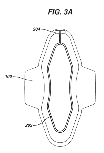
Fig. 3A is a diagrammatic representation of an exemplary feminine napkin with
sensor.
Fig. 3B is a diagrammatic representation of an exemplary attachment of a
signal
acquisition device to a feminine napkin and placement in underwear.
3
CA 03082530 2020-05-12
WO 2019/126606 PCT/US2018/067004
Fig. 3C shows an exemplary connector utilizing button snaps.
Fig. 4 is a top plan view of a personal hygiene product having a parallel
sensor
arrangement.
Fig. 5 is a diagrammatic representation of an alternative arrangement of the
sensor
element having three conductive traces.
Fig. 6 is a diagrammatic representation of an alternative arrangement of the
sensor
element having three modified conductive traces.
DETAILED DESCRIPTION OF THE PREFERRED EMBODIMENTS
A device comprising a hygiene product with a digital element capable of
interface with a
smart hand held electronic device is disclosed in this application. In the
following sections,
detailed descriptions of various embodiments are described. The descriptions
of various
embodiments are illustrative embodiments, and various modifications and
alterations may be
apparent to those skilled in the art. Therefore, the exemplary embodiments do
not limit the scope
of this application. The digital element is designed for use in or adjacent to
the body of a living
organism.
Glossary
In the description and claims below, various terms may be used for which the
following
definitions will apply:
"Biocompatible" as used herein refers to a material or device that performs
with an
appropriate host response in a specific application. For example, a
biocompatible device does not
have toxic or injurious effects on biological systems.
"Communication System" as used herein, may refer to a wireless communication
device
that can be configured to transmit and receive information from a processor to
a receiver in a
smart hand held electronic device.
"Digital Element" as used herein, may refer to electronic components on a
substrate.
4
CA 03082530 2020-05-12
WO 2019/126606 PCT/US2018/067004
"Smart Hand-held Device" as used herein, may refer to a smartphone or tablet
built on a
mobile operating system and having advanced processing capabilities.
"External Personal Hygiene Product" as used herein refers to but is not
limited to
Hygiene Products worn outside the body.
"Feminine Hygiene Product" as used herein refers to but is not limited to a
tampon,
sanitary pad, panty liner, nursing pad, or other product used to absorb or
contain menstruation or
bodily fluid discharge.
"Hygiene Product" as used herein refers to any absorbent material or device
used by
humans to absorb or contain bodily fluid discharge, including but not limited
to Feminine
Hygiene Products, diapers, men's guards and shields, adult diapers and booster
pads.
"Power Source" as used herein refers to any device or layer which can supply
energy or
placing a logical or electrical device in an energized state. The power source
may include
batteries. The batteries can be formed from alkaline cell chemistry and may be
solid-state
batteries or wet cell batteries.
"Sensor Array" as used herein means a sensor or a plurality of sensors, which
may
include, for example, resistive or capacitive to detect liquid or moisture.
"Switch" as used herein means a circuit element that controls the flow of
electrical
current in response to a physical or electrical input
Personal Hygiene Product with a Digital Element
The present invention is an improvement of a Personal Hygiene Product with a
digital
element as disclosed in US2016/0250081 and USSN 62/569,744, the entire
contents of which are
herein incorporated by reference.
External Personal Hygiene Product
Referring now to Figs. 1-3, there is illustrated a Personal Hygiene Product
100 having a
cover layer 102, a barrier layer 104, and an absorbent material 106 disposed
between the cover
layer 102, a barrier layer 104. The barrier layer 104 has an inner surface 108
directed toward the
absorbent material 106 and an outer, garment-facing surface 110. The Personal
Hygiene Product
100 may also have a positioning adhesive 112 disposed upon the outer surface
110 of the barrier
layer 104. The positioning adhesive 112 may be protected by a release liner
114.
CA 03082530 2020-05-12
WO 2019/126606 PCT/US2018/067004
Referring now to Fig. 3, an external electronic feminine hygiene system for
external
sanitary products, such as sanitary napkins, liners, and incontinence pads is
shown. Figure 3A
shows a Personal Hygiene Product 100 with embedded conductive elements, also
referred to as
sensor electrodes or traces 202. Such electrodes may be fabricated with
conductive ink,
metallized and transferred onto the pad, or through other methods. The ends of
the traces 202
form a connection point or node 204. Figure 3B shows said Personal Hygiene
Product 100 with a
signal acquisition device 206 attached, both against an undergarment Figure 3C
shows an
exemplary connector 208 in which metal button snaps 210 are crimped onto
conductive traces
202 on the Personal Hygiene Product 100.
When fluid reaches the area between the two parallel traces 202, the
resistance change is
read by the tag and an alarm is trigged (e.g. vibration or message sent to a
smartphone app). The
transmission can be direct (using bluetooth, for exemple) or indirect (using a
passive RFID). The
transmission can be non-stop or a passive tag can be scanned directly by the
smartphone,
whenever the user desires. By continuous is meant a sampling rate of about
1Hz.
The traces 202 are in parallel arrangement, but are oriented in a mirrored
configuration.
Thus, trace 202a extends from the connection point 204 in a clockwise
direction about the
product, and trace 202b extends from the connection point 204 in a counter-
clockwise direction
about the product. This provides a constant signal due to a change in system
resistance, no
matter where the bridging between the traces 202 occurs. In contrast to a
parallel arrangement
shown in Fig. 4 in which a short-circuit proximate the node 304, e.g., at a
point indicated at 306
would have a significantly different signal than a short-circuit distal the
node 304, e.g., at a point
indicated at 308.
The traces 202 may be disposed on any layer of the Personal Hygiene Product
100. In
one embodiment, the traces 202 are disposed on the inner surface 108 of the
barrier layer 104.
Alternatively, the traces 202 may be disposed on or in the absorbent material
106 or the cover
layer 102. However, we have found that conductive traces printed on porous
fibrous substrates
have a higher resistance due to ink adhesion and minimal gaps inherent in a
porous fibrous
structure. Preferably, the traces 202 are disposed on the inner surface 108 of
the barrier layer
104. This separates the traces from contact with the user's body.
The traces 202 may be in the form of conductive ink (e.g. silver or carbon-
based ink)
printed or otherwise disposed on a substrate, a wire (e.g., copper, silver,
carbon or other
6
CA 03082530 2020-05-12
WO 2019/126606 PCT/US2018/067004
conductive material) disposed on or contained within one or more structures of
the Personal
Hygiene Product 100.
One or more regions of the Personal Hygiene Product 100 may be embossed as is
known
to those of ordinary skill in the art.
In one embodiment, the sensor traces 202 are disposed towards the outer
margins 116 of
the Personal Hygiene Product 100 and all embossments, e.g., 118, are disposed
within a region
defined by the sensor traces 202.
In another embodiment shown in Fig. 5, a third conductive element 202c is
disposed
within the region defined by the sensor traces 202a, 202b. This provides an
earlier warning of
potential leakage than a simple pair of traces 202a, 202b.
The traces may be a continuous smooth line about the Personal Hygiene Product
100, or
they may be as shown in Fig. 6. Although these angled line segment traces are
shown for an
embodiment including three conductive traces, similar angled line segment
traces can be used for
a pair of parallel traces.
Other embodiments:
The absorbent article may have an absorbent core, an embossing pattern and a
humidity
detection sensor and a resistance reader coupled to a wireless transmission
element.
The Personal Hygiene Product may be used by connecting a resistance reader and
wireless transmission device to each of the node or contacting zones of the
sensor traces,
synchronizing the wireless transmission device to an alarm device, reading the
electrical
resistance between the least two electrically conductive traces, and alerting
when the resistance
changes (from infinite to less than 1 Mega ohms).
Humidity detection sensor is located at the external periphery of the
absorbent core,
outside a zone defined by the embossing pattern and inside a zone defined by
the edges of the
absorbent core.
Connection of the humidity detection sensor to a resistance reader+ wireless
transmission
device
Transmission of information to an alarm device, that will alert the user,
preferred:
Smartphone, smart watch or any mobile telecommunication device
Width of the conductive ink traces from 0.1mm to 5 mm (preferred between about
0.5
and about 1.5 mm, more preferred about 1 mm)
7
CA 03082530 2020-05-12
WO 2019/126606 PCT/US2018/067004
Spacing between adjacent conductive ink traces ranges from 0.1 mm to 5 mm
(preferred
between about 1.5 and about 2.5 mm, more preferred about 2 mm).
The electrically conductive traces are not in contact; the loop is open in its
initial state
and is closed when a liquid gets in contact with at least 2 tracks.
The connection node of the electrically conductive tracks have a surface of
between
about 65 mm2 and about 225 mm2, more preferably about 100 mm2 (preferably
between about
8mm x 8mm and 15mm x 15mm, most preferably about 10mm x lOmm), located on the
cover,
or core, or backing layer, or on the upper side of the absorbent article.
Wireless transmission device may be built inside the pad or
physically/electronically
connected to it through the contacting zones
Minimal distance between the electrically conductive tracks and the embossing
pattern
ranges between 0.1 mm to 5 mm (preferred 1 mm).
Resistance of the electrically conductive traces is less than 2000 ohms / sq,
prefereably
about 100 ohms / sq.
Although shown and described is what is believed to be the most practical and
preferred
embodiments, it is apparent that departures from specific designs and methods
described and
shown will suggest themselves to those skilled in the art and may be used
without departing from
the spirit and scope of the invention. The present invention is not restricted
to the particular
constructions described and illustrated, but it should be constructed to
cohere with all
modifications that may fall within the scope of the appended claims.
8