Note: Descriptions are shown in the official language in which they were submitted.
CA 03082626 2020-05-14
WO 2019/096557
PCT/EP2018/079242
Method for improving the cooling capacity of a gas solids olefin
polymerization reactor
The present invention is directed to a method for improving the cooling
capacity of a gas solids olefin polymerization reactor.
Background
Gas solids olefin polymerization reactors are commonly used for the
polymerization of alpha-olefins such as ethylene and propylene as they
allow relative high flexibility in polymer design and the use of various
catalyst systems. A common gas solids olefin polymerization reactor
variant is the fluidized bed reactor.
One of the biggest challenges of exothermic polymerization reactions in
gas solids olefin polymerization reactors is the cooling of the reactor. The
fluidization gas moving upwards through the dense phase in which the
polymerization reaction takes place and the polyolefin particles are
polymerized forms gas bubbles which entrain polyolefin powder into the
disengaging zone near to the fluidization gas exit. In order to prevent
excessive polyolefin powder entrainment into the fluidization gas stream
withdrawn from the top zone of the reactor the superficial gas velocity of
the fluidization gas stream has to be limited which, however, results in
inefficient mixing of the fluidized gas with the polyolefin powder in the
dense phase and reduced heat exchange.
US 5,428,118 discloses a process for polymerizing olefins in a gas phase
reactor in which hot fluidization gas withdrawn from the reactor is
reintroduced into the disengaging zone via a tangential flow of gas or gas-
solids.
WO 2017/025330 Al discloses a process for polymerizing olefins in a gas
phase reactor in which a cooled stream of partially condensed fluidization
gas withdrawn from the reactor is reintroduced into the disengaging zone.
CA 03082626 2020-05-14
WO 2019/096557 - 2 - PCT/EP2018/079242
Both prior art application are not concerned with an improved mixing of
the fluidized gas with the polyolefin powder in the dense phase resulting in
improved heat exchange and cooling capacity.
Thus, there is still a need in the art to provide a method for improving the
cooling capacity of a gas solids olefin polymerization reactor.
Summary of the invention
The present invention provides a method for improving the cooling
capacity of a gas solids olefin polymerization reactor comprising a top
zone, a middle zone, which comprises a top end in direct contact with said
top zone and which is located below said top zone, the middle zone
having a generally cylindrical shape, and a bottom zone, which is in direct
contact with a bottom end of the middle zone and which is located below
the middle zone, comprising the following steps:
a) introducing a first stream of fluidization gas into the bottom zone;
b) polymerizing olefin monomer(s) in the presence of a polymerization
catalyst in a dense phase formed by particles of a polymer of the olefin
monomer(s) suspended in an upwards flowing stream of the
fluidization gas in the middle zone;
C) withdrawing a second stream comprising the fluidization gas from the
top zone;
d) introducing the second stream into cooler;
e) withdrawing the cooled second stream from the cooler; and
f) splitting the cooled second stream into a cooled third stream and the
first stream;
introducing the cooled third stream through one or more feeding ports in a
feeding area of the middle zoneat the dense phase in the middle zone of
the gas solids olefin polymerization reactor.
CA 03082626 2020-05-14
WO 2019/096557 - 3 -
PCT/EP2018/079242
Further, the present invention is directed to the use of the method
according to any of the preceding claims for improving the mixing of the
fluidization gas and the particles of a polymer of the olefin monomer(s) in
the dense phase in the middle zone of the gas solids olefin polymerization
reactor.
Detailed Description
Definitions
The present text refers to diameter and equivalent diameter. In case of
non-spherical objects the equivalent diameter denotes the diameter of a
sphere or a circle which has the same volume or area (in case of a circle)
as the non-spherical object. It should be understood that even though the
present text sometimes refers to diameter, the object in question needs
not be spherical unless otherwise specifically mentioned. In case of non-
spherical objects (particles or cross-sections) the equivalent diameter is
then meant.
As it is well understood in the art the superficial gas velocity denotes the
velocity of the gas in an empty construction. Thus, the superficial gas
velocity within the middle zone is the volumetric flow rate of the gas (in
m3/s) divided by the cross-sectional area of the middle zone (in m2) and
the area occupied by the particles is thus neglected.
By fluidization gas is meant the gas comprising monomer, and eventual
comonomers, chain transfer agent and inert components which form the
upwards flowing gas in the gas solids olefin polymerization reactor and in
which the polymer particles are suspended, e.g. in the fluidized bed of a
fluidized bed reactor. The unreacted gas is collected at the top of the
reactor, compressed, cooled and returned to the reactor. As it is
understood by the person skilled in the art the composition of the
fluidization gas is not constant during the cycle. Reactive components are
consumed in the reactor and they are added into the circulation line for
compensating losses.
CA 03082626 2020-05-14
WO 2019/096557 - 4 -
PCT/EP2018/079242
A gas solids olefin polymerization reactor is a polymerization reactor for
heterophasic polymerization of gaseous olefin monomer(s) into polyolefin
powder particles, which comprises three zones: in the bottom zone the
fluidization gas is introduced into the reactor; in the middle zone which
usually has a generally cylindrical shape the olefin monomer(s) present in
the fluidization gas are polymerized to form the polymer particles; in the
top zone the fluidization gas is withdrawn from the reactor. In certain types
of gas solids olefin polymerization reactors a fluidization grid (also named
distribution plate) separates the bottom zone from the middle zone. In
certain types of gas solids olefin polymerization reactors the top zone
forms a disengaging or entrainment zone in which due to its expanding
diameter compared to the middle zone the fluidization gas expands and
the gas disengages from the polyolefin powder.
The dense phase denotes the area within the middle zone of the gas
solids olefin polymerization reactor with an increased bulk density due to
the formation of the polymer particles. In certain types of gas solids olefin
polymerization reactors, namely fluidized bed reactors, the dense phase is
formed by the fluidized bed.
"Entrained polyolefin powder" or "carry-over of particles" denotes
polyolefin particles which are withdrawn together with the fluidization gas
in the second stream of fluidization gas from the top zone of the gas solids
olefin polymerization reactor.
"Circulation gas line" denotes the system of lines or tubes through which
the second stream of fluidization gas is reintroduced into the gas solids
olefin polymerization reactor as first stream of fluidization gas and as
cooled third stream.
"Bulk density" (or "bed density" for fluidized bed polymerization reactors)
denotes mass of polymer powder divided by the volume of the reactor,
excluding the optional disengaging zone.
CA 03082626 2020-05-14
WO 2019/096557 - 5 -
PCT/EP2018/079242
In the present invention the different streams are measured as volume
streams so that also the split of these streams is meant as volume split
measured in v/v.
Differences in temperature AT are measured in C if not noted otherwise.
Differences in pressure AP are measured in bar if not noted otherwise.
Polymerization
The olefin monomer(s) polymerized according to the method of the
present invention are typically alpha-olefins having from 2 to 12 carbon
atoms, preferably from 2 to 10 carbon atoms. Preferably, the olefin
monomer(s) are ethylene or propylene, optionally together with one or
more other alpha-olefin monomer(s) having from 2 to 8 carbon atoms.
Especially preferably the method of the present invention is used for
polymerizing ethylene, optionally with one or more comonomers selected
from alpha-olefin monomer(s) having from 4 to 8 carbon atoms; or
propylene, optionally together with one or more comonomers selected
from ethylene and alpha-olefin monomer(s) having from 4 to 8 carbon
atoms.
Thus, the polymer material is preferably selected from alpha-olefin homo-
or copolymers having alpha-olefin monomer units of from 2 to 12 carbon
atoms, preferably from 2 to 10 carbon atoms. Preferred are ethylene or
propylene honno- or copolymers. The comonomer units of ethylene
copolymers are preferably selected from one or more comonomers
selected from alpha-olefin monomer(s) having from 4 to 8 carbon atoms.
The comonomer units of propylene copolymers are preferably selected
from one or more comonomers selected from ethylene and alpha-olefin
monomer(s) having from 4 to 8 carbon atoms.
In one preferred embodiment of the invention, in the method according to
the invention a polypropylene homo- or copolymer is polymerized from the
olefin monomer(s) and optional comonomer(s). Preferably, in this
embodiment, the polymerization is carried out at a temperature of 50-
CA 03082626 2020-05-14
WO 2019/096557 - 6 -
PCT/EP2018/079242
100 C under a pressure of 15-25 barg. Preferably, the molar ratios of the
reactants are adjusted as follows: a C2/C3 ratio of 0-0.05 mol/mol for
random polypropylenes, and a molar C2/C3 ratio of 0.2-0.7 mo/mol for
block polypropylenes. Generally, the H2/C3 molar ratio in this embodiment
is adjusted to 0-0.05 mol/mol. Moreover, in this embodiment, the
propylene feed is preferably adjusted to 20-40 t/h, whereby the
comonomer feed is 0-15 t/h and hydrogen feed is 1-10 kg/h.
In a second preferred embodiment of the invention, in the method
according to the invention a polyethylene homo- or copolymer is
polymerized from the olefin monomer(s) and optional comonomer(s).
Preferably, in this embodiment, the polymerization is carried out at a
temperature of 50-100 C under a pressure of 15-25 barg. Preferably, the
molar ratios of the reactants are adjusted as follows: a C4/C2 ratio of 0.1-
0.8 mol/mol for polyethylene-1-butene copolymers and a C6/C2 ratio of 0-
0.1 mol/mol for polyethylene-1-hexene copolymers. Generally, the H2/C2
molar ratio in this embodiment is adjusted to 0-0.05 mol/mol. Moreover, in
this embodiment, the ethylene feed is preferably adjusted to 15-20 t/h,
whereby the comonomer feed is adjusted to 0¨ 20 t/h for 1-butene and to
0-7 t/h for 1-hexene. Preferably, hydrogen feed is 1-100 kg/h and diluent
feed (propane): 30-50 t/h.
Polymerization catalyst
The polymerization in the gas-solids olefin polymerization reactor is
conducted in the presence of an olefin polymerization catalyst. The
catalyst may be any catalyst which is capable of producing the desired
olefin polymer. Suitable catalysts are, among others, Ziegler ¨ Natta
catalysts based on a transition metal, such as titanium, zirconium and/or
vanadium catalysts. Especially Ziegler ¨ Natta catalysts are useful as they
can produce olefin polymers within a wide range of molecular weight with
a high productivity.
CA 03082626 2020-05-14
WO 2019/096557 - 7 -
PCT/EP2018/079242
Suitable Ziegler ¨ Natta catalysts preferably contain a magnesium
compound, an aluminium compound and a titanium compound supported
on a particulate support.
The particulate support can be an inorganic oxide support, such as silica,
alumina, titania, silica-alumina and silica-titania. Preferably, the support
is
silica.
The average particle size of the silica support can be typically from 6 to
100 gm. However, it has turned out that special advantages can be
obtained if the support has median particle size from 6 to 90 gm,
preferably from 10 to 70 gm.
The magnesium compound is a reaction product of a magnesium dialkyl
and an alcohol. The alcohol is a linear or branched aliphatic monoalcohol.
Preferably, the alcohol has from 6 to 16 carbon atoms. Branched alcohols
are especially preferred, and 2-ethyl-1-hexanol is one example of the
preferred alcohols. The magnesium dialkyl may be any compound of
magnesium bonding to two alkyl groups, which may be the same or
different. Butyl-octyl magnesium is one example of the preferred
magnesium dialkyls.
The aluminium compound is chlorine containing aluminium alkyl.
Especially preferred compounds are aluminium alkyl dichlorides and
aluminium alkyl sesquichlorides.
The titanium compound is a halogen containing titanium compound,
preferably chlorine containing titanium compound. Especially preferred
titanium compound is titanium tetrachloride.
The catalyst can be prepared by sequentially contacting the carrier with
the above mentioned compounds, as described in EP-A-688794 or WO-A-
99/51646. Alternatively, it can be prepared by first preparing a solution
from the components and then contacting the solution with a carrier, as
described in WO-A-01/55230.
CA 03082626 2020-05-14
WO 2019/096557 - 8 -
PCT/EP2018/079242
Another group of suitable Ziegler ¨ Natta catalysts contains a titanium
compound together with a magnesium halide compound acting as a
support. Thus, the catalyst contains a titanium compound on a magnesium
dihalide, like magnesium dichloride. Such catalysts are disclosed, for
instance, in WO-A-2005/118655 and EP-A-810235.
Still a further type of Ziegler-Natta catalysts are catalysts prepared by a
method, wherein an emulsion is formed, wherein the active components
form a dispersed, i.e. a discontinuous phase in the emulsion of at least
two liquid phases. The dispersed phase, in the form of droplets, is
solidified from the emulsion, wherein catalyst in the form of solid particles
is formed. The principles of preparation of these types of catalysts are
given in WO-A-2003/106510 of Borealis.
The Ziegler ¨ Natta catalyst is used together with an activator. Suitable
activators are metal alkyl compounds and especially aluminium alkyl
compounds. These compounds include alkyl aluminium halides, such as
ethylaluminium dichloride, diethylaluminium chloride, ethylaluminium
sesquichloride, dimethylaluminium chloride and the like. They also include
trialkylaluminium compounds, such as
trimethylaluminium,
triethylaluminium, tri-isobutylaluminium, trihexylaluminium and tri-n-
octylaluminium. Furthermore they include alkylaluminium oxy-compounds,
such as methylaluminiumoxane (MAO), hexaisobutylaluminiumoxane
(HIBAO) and tetraisobutylaluminiumoxane (TIBAO). Also other aluminium
alkyl compounds, such as isoprenylaluminium, may be used. Especially
preferred activators are trialkylaluminiums, of which triethylaluminium,
trimethylaluminium and tri-isobutylaluminium are particularly used. If
needed the activator may also include an external electron donor. Suitable
electron donor compounds are disclosed in WO-A-95/32994, US-A-
4107414, US-A-4186107, US-A-4226963, US-A-4347160, US-A-4382019,
US-A-4435550, US-A-4465782, US 4472524, US-A-4473660, US-A-
4522930, US-A-4530912, US-A-4532313, US-A-4560671 and US-A-
4657882. Also electron donors consisting of organosilane compounds,
CA 03082626 2020-05-14
WO 2019/096557 - 9 -
PCT/EP2018/079242
containing Si-OCOR, Si-OR, and/or Si-NR2 bonds, having silicon as the
central atom, and R is an alkyl, alkenyl, aryl, arylalkyl or cycloalkyl with 1-
20 carbon atoms are known in the art. Such compounds are described in
US-A-4472524, US-A-4522930, US-A-4560671, US-A-4581342, US-A-
4657882, EP-A-45976, EP-A-45977 and EP-A-1538167.
The amount in which the activator is used depends on the specific catalyst
and activator. Typically triethylaluminium is used in such amount that the
molar ratio of aluminium to the transition metal, like Al/Ti, is from 1 to
1000, preferably from 3 to 100 and in particular from about 5 to about 30
mol/mol.
Also metallocene catalysts may be used. Metallocene catalysts comprise
a transition metal compound which contains a cyclopentadienyl, indenyl or
fluorenyl ligand. Preferably the catalyst contains two cyclopentadienyl,
indenyl or fluorenyl ligands, which may be bridged by a group preferably
containing silicon and/or carbon atom(s). Further, the ligands may have
substituents, such as alkyl groups, aryl groups, arylalkyl groups, alkylaryl
groups, silyl groups, siloxy groups, alkoxy groups or other heteroatom
groups or the like. Suitable metallocene catalysts are known in the art and
are disclosed, among others, in WO-A-95/12622, WO-A-96/32423, WO-A-
97/28170, WO¨A-98/32776, WO¨A-99/61489, WO¨A-03/010208, WO¨A-
03/051934, WO¨A-03/051514, WO¨A-2004/085499, EP-A-1752462 and
EP¨A-1739103.
Prior polymerization stages
The polymerization in the gas-solids olefin polymerization reactor may be
preceded by prior polymerization stages, such as prepolymerization or
another polymerization stage conducted in slurry or gas phase. Such
polymerization stages, if present, can be conducted according to the
procedures well known in the art. Suitable processes including
polymerization and other process stages which could precede the
polymerization process of the present invention are disclosed in WO-A-
CA 03082626 2020-05-14
WO 2019/096557 - 10 -
PCT/EP2018/079242
92/12182, WO-A-96/18662, EP-A-1415999, WO-A-98/58976, EP-A-
887380, WO-A-98/58977, EP-A-1860125, GB-A-1580635, US-A-4582816,
US-A-3405109, US-A-3324093, EP-A-479186 and US-A-5391654. As it is
well understood by the person skilled in the art, the catalyst needs to
remain active after the prior polymerization stages.
Gas-solids olefin polymerization
In the gas-solids olefin polymerization reactor polymerization is conducted
using gaseous olefin monomer(s) in which the polymer particles are
growing.
The present method is suitable for any kind of gas-solids olefin
polymerization reactors suitable for the polymerization of alpha-olefin
homo- or copolymers. Suitable reactors are e.g. continuous-stirred tank
reactors or fluidized bed reactors. Both types of gas-solids olefin
polymerization reactors are well known in the art.
Preferably the gas-solids olefin polymerization reactor is a fluidized bed
reactor.
In a fluidized bed reactor the polymerization takes place in a fluidized bed
formed by the growing polymer particles in an upwards moving gas
stream. In the fluidized bed the polymer particles, containing the active
catalyst, come into contact with the reaction gases, such as monomer,
connononner(s) and hydrogen which cause polymer to be produced onto
the particles.
Thereby, in one preferred embodiment the fluidized bed reactor can
comprise a fluidization grid which is situated below the fluidized bed
thereby separating the bottom zone and the middle zone of the reactor.
The upper limit of the fluidized bed is usually defined by a disengaging
zone in which due to its expanding diameter compared to the middle zone
the fluidization gas expands and the gas disengages from the polyolefin
powder. Fluidized bed reactors with disengaging zone and fluidization grid
CA 03082626 2020-05-14
WO 2019/096557 - 11 -
PCT/EP2018/079242
are well known in the art. Such a fluidized bed reactor suitable for the
method of the present invention is shown in Fig. 1.
In another preferred embodiment the fluidized bed reactor does not
comprise a fluidization grid. The polymerization takes place in a reactor
including a bottom zone, a middle zone and a top zone. The bottom zone,
which has a generally conical shape, forms the lower part of the reactor in
which the base of the fluidized bed is formed. The base of the bed forms
in the bottom zone with no fluidization grid, or gas distribution plate, being
present. Above the bottom zone and in direct contact with it is the middle
zone, which has a generally cylindrical shape. The middle zone and the
upper part of the bottom zone contain the fluidized bed. Because there is
no fluidization grid there is a free exchange of gas and particles between
the different regions within the bottom zone and between the bottom zone
and the middle zone. Finally, above the middle zone and in direct contact
therewith is the top zone which has a generally conical shape tapering
upwards.
The bottom zone of the reactor has a generally conical shape tapering
downwards. Because of the shape of the zone, the gas velocity gradually
decreases along the height within said bottom zone. The gas velocity in
the lowest part is greater than the transport velocity and the particles
eventually contained in the gas are transported upwards with the gas. At a
certain height within the bottom zone the gas velocity becomes smaller
than the transport velocity and a fluidized bed starts to form. When the
gas velocity becomes still smaller the bed becomes denser and the
polymer particles distribute the gas over the whole cross-section of the
bed. Such a fluidized bed reactor without fluidization grid is described in
EP-A-2 495 037 and EP-A-2 495 038.
In a gas solids olefin polymerization reactor the upwards moving gas
stream is established by withdrawing a fluidization gas stream as second
gas stream from the top zone of the reactor, typically at the highest
location. The second gas stream withdrawn from the reactor is then
CA 03082626 2020-05-14
WO 2019/096557 - 12 -
PCT/EP2018/079242
cooled and re-introduced to the bottom zone of the reactor as first stream
of fluidization gas. In a preferred embodiment, the fluidization gas of the
second gas stream is also compressed in a compressor. More preferably,
the compressor is located upstream of the cooler. Preferably, the gas is
filtered before being passed to the compressor. Additional olefin
monomer(s), eventual comonomer(s), hydrogen and inert gas are suitably
introduced into the circulation gas line. It is preferred to analyze the
composition of the circulation gas, for instance, by using on-line gas
chromatography and adjust the addition of the gas components so that
their contents are maintained at desired levels.
The polymerization is generally conducted at a temperature and pressure
where the fluidization gas essentially remains in vapour or gas phase. For
olefin polymerization the temperature is suitably within the range of 30 to
110 C, preferably 50 to 100 C. The pressure is suitably in the range of 1
to 50 bar, preferably 5 to 35 bar.
In order to remove entrained polyolefin powder the circulation gas line, i.e.
the line for withdrawing the second stream, preferably comprises at least
one cyclone. The cyclone has the objective of removing the entrained
polymer material from the circulation gas. The polymer stream recovered
from the cyclone can be directed to another polymerization stage, or it
may be returned into the gas solids olefin polymerization reactor or it may
be withdrawn as the polymer product.
In the case the polymer stream recovered from the cyclone is returned into
the gas-solids polymerization reactor the polymer stream is returned
through one or more feedings ports, which are different feeding ports as
the one or more feeding ports for introducing the cooled third stream into
the dense phase in the middle zone of the gas-solids olefin polymerization
reactor.
Preferably, the cooled third stream comprises not more than 5 wt% solid
polymer with respect to the total weight of the cooled third stream, more
CA 03082626 2020-05-14
WO 2019/096557 - 13 -
PCT/EP2018/079242
preferably not more than 3 wt% solid polymer, even more preferably not
more than 2 wt% solid polymer and most preferably not more than 1 wt%
solid polymer.
Circulation of the fluidized gas
According to the present invention the fluidization gas is withdrawn from
the top zone of the reactor as second stream, optionally compressed by a
compressor, introduced into a cooler, withdrawn from the cooler as cooled
second stream and split into a cooled third stream and the first stream.
The first stream is introduced into the reactor into the bottom zone
whereas the cooled third stream is introduced into the reactor through one
or more feeding ports in a feeding area of the middle zone at the dense
phase in the middle zone of the reactor. Thereby, the third stream is not
mixed with particles of the polymer of the olefin monomer(s) before
entering the reactor and thus is not introduced into the reactor through
feeding ports for reintroducing particles of the polymer of the olefin
monomer(s) into the gas solids olefin polymerization reactor.
The feeding area of the middle zone is preferably located on the surface
of the middle zone between the top end and 50% of the total height of the
middle zone, whereas the bottom end corresponds to 0% and the top end
corresponds to 100% of the total height of the middle zone. More
preferably, the feeding area of the middle zone is located on the surface
of the middle zone between the top end and 70% of the total height of the
middle zone.
Preferably, the cooled third stream is introduced through the one or more
feeding ports into the dense phase in the middle zone of the gas solids
olefin polymerization reactor in an introduction angle of 50 to 75 ,
preferably 10 to 65 , most preferably 15 to 60 . The introduction angle is
the angle between a projection and a perpendicular line, whereas the
projection is the projection of the direction of the cooled third stream after
introduction into the reactor on a projection plane, which crosses the
CA 03082626 2020-05-14
WO 2019/096557 - 14 -
PCT/EP2018/079242
tangent plane of the generally cylindrical shape of the middle zone at the
location of the one or more feeding ports and along an intersection line
between the tangent plane and the generally cylindrical surface of the
middle zone, whereas the projection plane is located perpendicular to the
tangent plane and whereas the perpendicular line crosses the generally
cylindrical surface of the middle zone at the location of the one or more
feeding ports, is parallel to the projection plane and is perpendicular to the
tangent plane (cf. Figure 2).Most preferably, the optimal introduction angle
for introducing the cooled third stream has been found to be about 200
.
The number of feeding ports for introducing the cooled third stream is in
the range of preferably 1 to 15, more preferably 2 to 10 and most
preferably 2 to 5.
The feeding ports are preferably distributed across the middle zone of the
gas solids olefin polymerization reactor in axial and/or radial direction with
the proviso that the cooled third stream is introduced into the dense
phase.
Preferably, the fluidization gas of the cooled third stream is compressed
by a compressor. The compressor could either be located upstream or
downstream of the cooler. Even more preferably, before being introduced
into the cooler, the second stream is introduced into a compressor;
withdrawn from the compressor as the compressed second stream and
introduced as compressed second stream into the cooler.
In the cooler the second stream is preferably cooled as such that the
cooled second stream, and as a consequence also the cooled third stream
and/or the first stream, comprise condensed fluidization gas, preferably
together with gaseous fluidization gas. Preferably, the cooled second
stream and as a consequence also the cooled third stream and/or the first
stream, comprise from 1 to 30 wt% condensed fluidization gas, more
preferably from 3 to 25 wt% condensed fluidization gas and most
preferably from 5 to 20 wt% condensed fluidization gas, based on the total
CA 03082626 2020-05-14
WO 2019/096557 - 15 -
PCT/EP2018/079242
weight of the cooled second stream and as a consequence also the
cooled third stream and/or the first stream. The remaining weight of the
cooled second stream and as a consequence also the cooled third stream
and/or the first stream preferably consists of gaseous fluidization gas.
In another embodiment the cooled second stream is not condensed or
partly condensed and does not comprise condensed fluidization gas. As a
consequence also the cooled third stream and the first stream in said
embodiment do not comprise condensed fluidization gas.
The cooled second stream is split into the cooled third stream and the first
stream at a ratio of 5:95 (v/v) to 75:25 (v/v), preferably 7:93 (v/v) to 65:35
(v/v), most preferably 10:90 (v/v) to 50:50 (v/v).
Depending on the volume split between the cooled third stream and the
first stream the cooled third stream has a certain pressure and contributes
to the superficial gas velocity of the upwards flowing stream in the middle
zone of the reactor.
The pressure difference between the cooled third stream and the
polymerization pressure in the gas solids polymerization reactor, AP, is at
least 0.1 bar, preferably at least 0.3 bar, most preferably at least 0.5 bar.
The upper limit for the pressure difference is usually not higher than 10
bar, preferably not higher than 7 bar.
It is further preferred that the superficial gas velocity of the upwards
flowing stream of the fluidization gas in the middle zone of the reactor is
from 0.3 to 1.2 m/s, more preferably from 0.35 to 1.0 m/s, most preferably
from 0.45 to 0.9 m/s.
Thereby, the superficial gas velocity of the first stream of fluidization gas
introduced into the bottom zone is preferably lower than the superficial
gas velocity of the upwards flowing stream of the fluidization gas in the
middle zone and is preferably in the range of from 0.1 to 1.3 m/s, more
preferably of from 0.15 to 1.1 m/s, most preferably of from 0.2 to 1.0 m/s.
CA 03082626 2020-05-14
WO 2019/096557 - 16 -
PCT/EP2018/079242
The bulk density of the dense phase during polymerization is in the range
of from 100 to 500 kg/m3, preferably of from 120 to 470 kg/m3, most
preferably of from 150 to 450 kg/m3.
It has been found that the introduction of the cooled third stream into the
dense phase in the middle zone of the gas solids olefin polymerization
reactor improves the mixing of the fluidization gas and the particles of a
polymer of the at least one olefin in the dense phase in the middle zone of
the gas solids olefin polymerization reactor. As a consequence the heat
exchange and the cooling capacity is improved.
Preferably, the difference of the maximum temperature and the minimum
temperature, AT, of the dense phase during polymerization is not higher
than 10 C, more preferably not higher than 7 C, still more preferably not
higher than 5 C and most preferably not higher than 3 C.
Benefits of the invention
It has been found that the introduction of the cooled third stream into the
dense phase in the middle zone of the gas solids olefin polymerization
reactor improves the mixing of the fluidization gas and the particles of a
polymer of the at least one olefin in the dense phase in the middle zone of
the gas solids olefin polymerization reactor to more even mixing
conditions.
As a consequence the heat removal from the dense phase is more
enhanced.
The temperature profile throughout the dense phase is more even with a
minimum difference of the maximum temperature and the minimum
temperature, AT, of the dense phase during polymerization.
The more even temperature profile leads to more homogeneous
polymerization conditions throughout the dense phase resulting in more
homogeneous polyolefin products. As a consequence, the risk to produce
off spec polymer material is substantially reduced.
- 17 -
Brief Description of Drawings
Fig. 1 shows an embodiment of the polymerization process according to the
present invention in a fluidized bed reactor with a fluidization grid.
Fig. 2 shows the experimental set-up of the temperature measurement in the
experimental part.
Fig. 3 shows the definition of the introduction angle of the cooled third
stream.
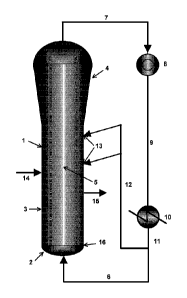
Reference signs for Fig 1
1 fluidized bed reactor
2 bottom zone
3 middle zone
4 disengaging zone (top zone)
fluidized bed (dense zone)
6 first stream of fluidized gas
7 second stream of fluidized gas
8 compressor
9 compressed second stream of fluidized gas
cooler
11 cooled second stream of fluidized gas
12 cooled third stream of fluidized gas
13 feeding ports for the cooled third stream of fluidized gas
14 feeding port for polymerization catalyst
polymer withdrawal
16 fluidization grid
Description of Fig 1
Date Recue/Date Received 2021-09-22
CA 03082626 2020-05-14
WO 2019/096557 - 18 -
PCT/EP2018/079242
Fig 1 shows an embodiment of the gas solids olefin polymerization reactor
system according to the present invention. The fluidized bed reactor (1)
comprises a bottom zone (2), a middle zone (3) and a disengaging zone
as top zone (4). The middle zone (3) and the bottom zone (2) are
separated by the fluidization grid (16). The first stream of fluidized gas (6)
enters the fluidized bed reactor (1) through the bottom zone (2) and flows
upwards, thereby passing the fluidization grid (16) and entering the middle
zone (3). Due to the substantially cylindrical shape of the middle zone (3)
the gas velocity is constant so that above the fluidization grid (16) the
fluidized bed (5) is established in the middle zone (3). Due to the conical
shape of the disengaging zone (4) the gas entering the disengaging zone
(4) expands so that the gas disengages from the polyolefin product of the
polymerization reaction so that the fluidized bed (5) is confined in the
middle zone (3) and the lower part of the disengaging zone (4). The
polymerization catalyst is introduced into the fluidized bed reactor (1)
through feeding port (14) directly into the fluidized bed (5). The polyolefin
product of the polymerization process is withdrawn from the fluidized bed
reactor through outlet (15).
The fluidized gas is withdrawn from the disengaging zone (4) as second
stream of fluidization gas (7) and introduced into a compressor (8). The
compressed second stream (9) is withdrawn from the compressor (8) and
introduced into a cooler (10). The cooled second stream (11) is withdrawn
from the cooler (10) and split into a third cooled stream (12) and the first
stream (6). The cooled third stream (12) is introduced into fluidized bed
(5) of the fluidized bed reactor (1) through one or more feeding ports (13)
as such that the fluidized gas of the cooled third stream (12) is directed
into the fluidized bed (5).
CA 03082626 2020-05-14
WO 2019/096557 - 19 -
PCT/EP2018/079242
Reference signs for Figure 3
a projection of the direction of the cooled third stream
perpendicular line
projection plane
d tangent plane
location of the feeding port
intersection line
generally cylindrical surface of the middle zone
a introduction angle
y angle between planes (c) and (d)
Description of Figure 3
Fig. 3 demonstrates the definition of the introduction angel a of the cooled
third stream. Said introduction angle (a) is the angle between a projection
(a) and a perpendicular line (b), whereas the projection (a) is the
projection of the direction of the cooled third stream after introduction into
the reactor on a projection plane (c), which crosses the tangent plane (d)
of the generally cylindrical shape (g) of the middle zone at the location of
the one or more feeding ports (e) and along an intersection line (f)
between the tangent plane (d) and the generally cylindrical surface (g) of
the middle zone, whereas the projection plane (c) is located perpendicular
to the tangent plane (d) (y = 90 ) and whereas the perpendicular line (b)
crosses the generally cylindrical surface (g) of the middle zone at the
location of the feeding port (e), is parallel to projection plane (c) and is
perpendicular to tangent plane (d).
CA 03082626 2020-05-14
WO 2019/096557 - 20 -
PCT/EP2018/079242
Examples
Fig 2 shows the reactor set-up used for the example 1 of the present
invention. Thereby, the dimensions of the reactor set-up are given in Fig
2. The reactor set-up comprises a fluidized bed reactor comprising a
fluidization grid (or distributor plate) into which before the start of the
experiments HDPE powder was filled.
Example 1
The experimental set up mentioned above was employed to assess the
effect of the spit fluidized gas concept on the cooling capability and the
thermal homogeneity in the fluidized bed reactor. Through the gas inlet at
the bottom of the fluidized bed reactor cold fluidization gas was introduced
at a volumetric feeding rate equal to 137 m3/h to establish a superficial
gas velocity just above the fluidization grid of 0.54 m/s so that a fluidized
bed of HDPE with a height of 86 cm was established in the middle zone of
the reactor above the fluidization grid. The superficial gas velocity at the
end of the fluidized reactor horizontal part (i.e., end of dense phase) was
kept constant at 0.54 m/s throughout the whole experiment.
The temperature in the fluidized bed reactor is measured throughout the
whole experiment at three measuring points T1, located at a point of 5 cm
above the distribution plate, T2, located at a point of 80 cm above the
distribution plate and T3, located at a point of 136 cm above the
distribution plate. Thereby, at measuring points T1 and T2 the temperature
of the dense phase of the fluidized bed is measured whereas at measuring
point T3 a mixed temperature of gas and solid in the lean phase of the
fluidized bed above the dense phase of the fluidized bed is measured.
2.5 min after starting to introduce cold fluidization gas the heating of the
fluidization gas was switched on and the fluidization gas was controlled to
have a temperature of 100 C at the entry at the bottom end of the fluidized
bed. The hot fluidization gas feed was kept at a constant flow of 137 m3/h.
The HDPE powder in the fluidized bed was heated by the hot fluidization
CA 03082626 2020-05-14
WO 2019/096557 - 21 -
PCT/EP2018/079242
gas until thermal equilibrium was reached after about 70 min after starting
to introduce hot fluidization gas. The temperature measurement points T1
and T3 were deviating from each other by approximately 3 C showing that
the gas-solid mixing conditions in the bed is not ideal (i.e., T1 = 73 C and
T3 =70 C).
72 min after starting to introduce hot fluidization gas from the bottom of
the reactor, its volumetric flow rate was reduced from 137 m3/h to 91 m3/h
and at the same time cooled fluidization gas circulation stream (i.e., at
temperature equal to 25 C) was reintroduced into the fluidized bed
reactor through a injection point in the middle zone of the fluidized bed
reactor into the dense zone of the HDPE powder in a downwards direction
in an angle of 20 , determined from the general cylindrical shape of the
middle zone. The cooled fluidization gas circulation stream had a constant
flow of 46 m3/h and a pressure difference between that injection point and
the fluidized bed reactor was equal to 3 bar (i.e., AP = 3 bar). With the
constant flow of the hot fluidization gas of 91 m3/h, the split of the cooled
fluidization gas circulation stream (JG) and the hot fluidization gas stream
(FG) was 33.5 : 66.5 (v/v).
After introducing the cooled fluidization gas circulation stream at t = 72
min the temperature at all three measuring points drops by about 10 C
until again an equilibrium is obtained.
It has to be highlighted that during the heating phase of the HDPE powder
in the fluidized bed at t = 2.5 min to t = 72 min the temperatures of the
dense phase of the fluidized bed T1 and T3 were deviating each other by
3 C. After introducing the cooled fluidization gas circulation stream all the
three measuring points were exactly the same (Ti = T2 = T3 = 60 C).
The contact of the cooled fluidization gas circulation stream and the HDPE
powder in the fluidized bed leads to an improved mixing of the polymer
powder in the fluidized bed resulting in an efficient heat exchange and a
decreasing fluidized bed temperature. From the same temperature profile
CA 03082626 2020-05-14
WO 2019/096557 - 22 -
PCT/EP2018/079242
at the measuring points of the dense phase of the fluidized bed T1 and T2
and the measuring point of the mixed temperature of gas and solid in the
lean phase of the fluidized bed T3 it can be concluded that the cooled
fluidization gas circulation stream contributes to sufficient heat removal
from the fluidized bed.
Examples 2 - 4:
In Examples 2 ¨ 4, the same reactor set-up used for the Example 1 was
employed with the only difference being that T1 was located at the middle
of the dense zone of the fluidized bed reactor, T2 was located at the inlet
pipe of the cooled fluidization gas circulation stream and T3 was located at
the top gas pipe exit (see Figure 3).
Example 2 (comparative):
Through the gas inlet at the bottom of the fluidized bed reactor hot
fluidization gas (FG) was introduced at a feeding rate equal to 150 rri3/h to
establish a superficial gas velocity just above the fluidization grid of 0.60
m/s. The superficial gas velocity at the end of the fluidized reactor
horizontal part (i.e., end of dense phase) was kept constant at 0.60 m/s
throughout the whole experiment.
The temperature in the fluidized bed reactor after 60 min of operation
reached a steady state value (thermal equilibrium) of 60 C measured at
three measuring points T1 (located at the middle of the dense reactor
zone), T2 (located at the cooled fluidization gas circulation stream) and T3
(located at the top gas pipe exit). The hot fluidization gas feed was kept at
a constant flow of 150 m3/h.
62 min after starting to introduce hot fluidization gas into the bottom zone
of the fluidized bed reactor, the fluidization gas withdrawn from the top
zone of the fluidized bed reactor was directed through a
compressor/cooler unit in order to cool it down to a temperature equal to
25 C before re-introducing the cooled fluidization gas (FG) stream into
the bottom zone of the fluidized bed reactor. The volumetric gas flow rate
CA 03082626 2020-05-14
WO 2019/096557 - 23 -
PCT/EP2018/079242
of the cooled fluidization gas was not changed and it was equal to 150
m3/h. No cooled fluidization gas circulation (jet gas (JG)) stream was used
and the split between the jet gas (JG) stream and the fluidization gas (FG)
stream was 0.0 : 100.0 (v/v).
The temperature in the dense phase of the fluidized bed captured by the
measurement point T1 was equal to 60 C at the steady state operation
(introduction of hot FG stream). After that the fluidized bed was cooled by
using only cooled fluidization gas (FG) for 30 min.
The temperature decrease rate in the fluidized bed reactor (measured at
measure point Ti) after 10 min, 20 min and 30 min (T1 o, AT20 and AT30)
was equal to 15 C/10 min, 20.5 C/20 min and 25 C/30 min, respectively.
The main conditions and results of this experiment are summarized in
Table 1.
Table 1: Conditions and main results of Example 2.
Conditions Values
JG Pressure drop [bar] 0
JG Flow [m3/h] (Y() Split (v/v)) 0 (0% split)
FG Flow [m3/h] (% Split (v/v)) 150.0 (100% Split)
Overall Gas Feed [m3/h] 150.0
SGVFG [m/s] 0.60
SGV
total r LM, 0.60
Final bulk density (Kg/m3) 250
ATio ( C/10 min) 15
AT20 ( C/20 min) 20.5
AT30 ( C/30 min) 25
Example 3 (Inventive)
The Example 2 was repeated. Heating of the bed fluidization bed reactor
was performed following the procedure described in Example 2. The
temperature in the fluidized bed reactor after 60 mins of operation reached
CA 03082626 2020-05-14
WO 2019/096557 - 24 -
PCT/EP2018/079242
a steady state value (thermal equilibrium) of 60 C measured at three
measuring points T1 (located at the middle of the dense reactor zone), T2
(located at the cooled fluidization gas circulation stream) and T3 (located
at the top gas pipe exit). The hot fluidization gas feed was kept at a
constant flow of 150 m3/h.
62 min after starting to introduce hot fluidization gas from the bottom of
the fluidized bed reactor, the fluidization gas withdrawn from the top zone
of the fluidized bed reactor was directed through a compressor/cooler unit
in order to cool it down to a temperature equal to 25 C. The volumetric
gas flow rate of the cooled fluidization gas (FG) stream re-introduced into
the bottom zone of the fluidized bed reactor was reduced from 150 m3/h to
110 m3/h. In this experiment cooled fluidization gas circulation (jet gas
(JG)) stream having a temperature of 25 C was introduced into the
fluidized bed reactor through an injection point in the middle zone of the
fluidized bed reactor into the dense zone of the HDPE powder in a
downwards direction in an angle of 20 , determined from the general
cylindrical shape of the middle zone (AP for injecting the JG was 5.0 bar,
see Table 2) and the split between the fluidization gas circulation stream
(JG) and the fluidization gas stream (FG) was 26.7 : 73.3 (v/v).
The temperature in the dense phase of the fluidized bed captured by the
measurement point T1 was equal to 60 C at the steady state operation
(introduction of hot FG stream). After that, the fluidized bed reactor was
cooled by using both FG and JG for 30 min.
The temperature decrease rate in the fluidized bed reactor ((measured at
measure point Ti)) after 10 min, 20 min and 30 min (ATio, AT20 and ATM)
was equal to 17 C/10 min, 24.5 C/20 min and 28 C/30 min, respectively.
The main conditions and results of this experiment are summarized in
Table 2.
CA 03082626 2020-05-14
WO 2019/096557 - 25 - PCT/EP2018/079242
Table 2: Conditions and main results of Example 3.
Conditions Values
JG Pressure drop [bar] 5
JG Flow [m3/h] (% Split (v/v)) 40.0 (26.7% split)
FG Flow [m3/h] (% Split (v/v)) 110.0 (73.3% Split)
Overall Gas Feed [m3/h] 150.0
SGVFG [m/s] 0.43
SGV
total LM, Si 0.60
Final bulk density (Kg/m3) 330
ATio ( C/10 min) 17
AT20 ( C120 min) 24.5
AT30 ( C130 min) 28
Example 4 (Inventive)
The Example 2 was repeated. Heating of the bed fluidization bed reactor
was performed following the procedure described in Example 2. The
temperature in the fluidized bed reactor after 60 mins of operation reached
a steady state value (thermal equilibrium) of 60 C measured at three
measuring points T1 (located at the middle of the dense reactor zone), T2
(located at the cooled fluidization gas circulation stream) and T3 (located
at the top gas pipe exit). The hot fluidization gas feed was kept at a
constant flow of 150 m3/h.
62 min after starting to introduce hot fluidization gas from the bottom of
the fluidized bed reactor, the fluidization gas withdrawn from the top zone
of the fluidized bed reactor was directed through a compressor/cooler unit
in order to cool it down to a temperature equal to 25 C. The volumetric
gas flow rate of the cooled fluidization gas (FG) stream re-introduced into
the bottom zone of the fluidized bed reactor was reduced from 150 m3/h to
110 m3/h. In this experiment cooled fluidization gas circulation (jet gas
(JG)) stream having a temperature of 25 C was introduced into the
fluidized bed reactor through an injection point in the middle zone of the
CA 03082626 2020-05-14
WO 2019/096557 - 26 - PCT/EP2018/079242
fluidized bed reactor into the dense zone of the HDPE powder in a
downwards direction in an angle of 200, determined from the general
cylindrical shape of the middle zone (AP for injecting the JG was 2.25 bar,
see Table 3) and the split between the fluidization gas circulation stream
(JG) and the fluidization gas stream (FG) was 26.7 : 73.3 (v/v).
The temperature in the dense phase of the fluidized bed captured by the
measurement point T1 was equal to 60 C at the steady state operation
(introduction of hot FG stream). After that, the fluidized bed reactor was
cooled by using both FG and JG for 30 min.
The temperature decrease rate in the fluidized bed reactor (measured at
measure point Ti) after 10 min, 20 min and 30 min (ATio, AT20 and AT30)
was equal to 16 C/10 min, 23.5 C/20 min and 28 C/30 min, respectively.
The main conditions and results of this experiment are summarized in
Table 3.
Table 3. Conditions and main results of Example 4.
Conditions Values
JG Pressure drop [bar] 2.25
JG Flow [m3/h] (`)/0 Split (v/v)) 40.0 (67.7% split)
FG Flow [m3/h] (% Split (v/v)) 110.0 (73.3% Split)
Overall Gas Feed [m3/1-1] 150.0
SGVFG [m/s] 0.43
SGV
total r LIM Si 0.60
Final bulk density (Kg/m3) 325
ATio ( C/10nnin) 16
AT20 ( C/20min) 23.5
AT30 ( C/30min) 28
By comparing the results depicted in Table 1 with those shown in Tables 2
and 3 it can be seen that the use of JG has a positive influence on the
cooling effect/capacity in the fluidized bed reactor. More specifically, the
CA 03082626 2020-05-14
WO 2019/096557 - 27 -
PCT/EP2018/079242
cooling rate in the fluidized bed reactor, expressed by ATio, AT20 and
AT30, is enhanced when JG is used. It is also apparent that even at a
lower pressure drop AP for injecting the JG, the cooling effect of JG in the
fluidized bed reactor is fully maintained and is better compared to
comparative example 1 where all the fluidization gas was introduced from
the bottom of the fluidized bed reactor. Similarly, the fluidized bulk density
attains higher values (i.e., 330 kg/m3 and 325 kg/m3) compared to
comparative example 1 (i.e., 250 kg/m3), which is a direct indication of
solids carry reduction.