Note: Descriptions are shown in the official language in which they were submitted.
Drill-powered Ebike
Background of the invention
Field of the Invention
This invention relates to electric-assist bicycle propulsion systems and more
particularly to an
articulated bracket that pendulously affixes a drill-powered friction-wheel
between a pushbike's
frame and one of its tires, thereby converting the pushbike into a friction-
drive "Ebike".
Description of the Prior Art
The "pushbike" (bicycle) was one of the first inventions to be patented so
there exists a wide
variety of granted IP as well as many non-patented but innovative commercial
products;
furthermore, there are a variety of relevant hobbyist projects that have been
documented on
YouTube. Together, they provide a broad scope of prior art that is relevant to
the present
invention.
A significant milestone in bicycle evolution was the introduction of electric-
assist propulsion to
ease the rider's physical burden. Various motorized drive configurations have
been devised
that enable two broad categories of Ebike propulsion systems. Mechanical-drive
systems apply
torque to the pushbike's rear-wheel drive gear-train. Friction-drive systems
use a friction-wheel
to apply torque directly onto one of the pushbike's tires and thereby counter-
rotating it forward.
In 1899, John Schnepf's US patent 627 066 disclosed one of the earliest
friction-drive electric-
assist propulsion systems; since then, many mechanical-drive and friction-
drive Ebikes have
been proposed. Three examples of relevant friction-drive Ebike patents are:
Battlogg et al. (US
5,816,355), Dennis (US 5,842,535) and Olsommer (US 9,975,602 B2); each of
these Ebike
configurations utilize one or more motorized friction-wheels, held against the
pushbike's front or
rear tire to propel it forward.
Various friction-drive kits for converting a pushbike into an Ebike are also
on the market. Below
is a list of relevant websites:
https://www.alizetibikes.com/
https://revolutionworks.com/
http://www.hiddenpower.co.kr/international/ (also see W02010134793)
https://www.rubbee.co.uk/
http://www.velogical-engineering.com/
https://sites.google.com/site/commuterbooster/home
These prior art friction-drive conversion kits are constrained by the need to
provide a dedicated
battery, a dedicated motor/controller and a dedicated drive mechanism. This
results in a
complex apparatus that is expensive to manufacture; furthermore, it cannot be
used for any
other purpose than to propel the bicycle. Ideally, all or part of an Ebike
conversion kit could be
Page 1
Date Recue/Date Received 2020-06-09
used for other applications when not being used for transportation, thereby
improving the kit's
versatility and cost-effectiveness.
Concurrent with the evolution of both bicycles and Ebikes, battery-powered
tools, such as
cordless drills, have experienced ongoing improvements to both their battery
life and their
electromotive efficiency. The major manufacturers now produce a "family" of
workshop and
industrial cordless tools as well as a variety of cordless home maintenance
accessories. To
improve their cost-effectiveness, all members of each company's cordless power-
tool family are
designed to share the same swappable battery modules.
Given the ubiquity and versatility of these swappable, cordless-tool battery
packs, it would be
desirable to devise a means for efficiently extending their range of
applications to include
powering an Ebike. Towards that end, a few fledgling efforts have been made to
utilize a
cordless drill to propel a bicycle. Below is a list of articles and videos
that document various
"DrillBike" DIY Ebike projects that have been made to date:
https://www.asme.org/topics-resources/content/make-way-for-drillpowered-bikes
https://makezine.com/projects/the-drill-rod/
https://www.youtube.com/watch?v=gC3rB9f7DaU
https://www.youtube.com/watch?v=_eWK4RdjCwc
https://www.youtube.com/watch?v=grcskPrbsvl
https://www.youtube.com/watch?v=7N-1A-RLLdQ
https://www.youtube.com/watch?v=0Z8dFIVNrY8
https://www.youtube.com/watch?v=mGu4iFK9y3U
https://www.youtube.com/watch?v=MxmkrXXKAJU
https://www.youtube.com/watch?v=fXGirSOBaWo
https://www.youtube.com/watch?v=KjeL3HbpknY
https://www.youtube.com/watch?v=vx7qYXn9drA
As is evident in the above articles and videos, the general configuration of a
cordless drill makes
it poorly suited for powering an Ebike. The complex or flimsy drill-holding
strategies and power-
transfer strategies tried to date have resulted in scooter-type vehicles that
are barely usable;
their efficiency is particularly poor when the vehicle is coasting (because
the stopped drill
typically acts as a brake).
The present invention rectifies the above-mentioned drawbacks in the prior
art, thereby
providing a simpler, more versatile and more cost-effective drill-powered
Ebike. The invention
in its general form will first be summarized by a concise textual description
of its principal
embodiments, and then its implementation will be described with reference to
the drawings
following hereafter. These embodiments are intended to demonstrate the
principle of the
invention, and the manner of its implementation. The invention in its broadest
and more specific
forms will then be further described, and defined, in each of the individual
claims which
conclude this Specification.
Page 2
Date Recue/Date Received 2020-06-09
Summary Of The Invention
An articulated bracket that clamps a pendulously-hanging friction-wheel onto
the frame of a
pushbike, thereby converting it into an Ebike capable of being powered by any
cordless drill.
The protruding central driveshaft of the friction-wheel is gripped in the
drill's chuck; when rotated
by the drill, the pendulum's cam geometry with respect to one of the
pushbike's tires causes the
friction-wheel to be forced against the tire, thereby propelling the tire and
pushbike forward. An
anti-torque arm mounted on the pendulum blocks counter-rotation of the drill's
housing which, if
left unchecked, would spin the entire drill and thereby prevent power transfer
into the pushbike's
driven tire. To enable the rider to control power to the driven wheel, a
handlebar-mounted cable
mechanism actuates the drill's trigger. In a more energy-efficient embodiment,
the friction-
wheel includes an internal ratchet mechanism freewheels to enable friction-
free pedalling or
coasting while the drill's trigger is released.
Note regarding definitions and nomenclature:
The scope of the term "pushbike" includes all "Human Powered Vehicles" (HPVs)
that are
propelled over the ground by a user "pushing" with one or more of their limbs.
While the
ubiquitous two-wheeled "Bicycle" is the most common pushbike, the three-
wheeled "Tricycle" is
also propelled as a "pushbike"; the friction-drive mechanism of the present
invention can be
configured to apply electric-assist to both two-wheeled and three-wheeled
pushbikes. Similarly,
the "Unicycle", the "Skateboard", the "Kickbike" and the "Pedicar" are HPVs
that have (more
limited) potential for being fitted with the present invention. The invention
might therefore be
titled "Drill-powered HPV" or "Drill-powered Pushbike" however the chosen
"Drill-powered Ebike"
title relates to its most socially relevant application: that of converting
existing bicycles into cost-
effective "Ebikes". Similarly, the title term "Drill-powered" is does not
cover the full scope of the
invention; several of its embodiments do not utilize a drill for electromotive
power. To include
those embodiments, a title such as "Electric-assist Pushbike" or "Electric-
assist HPV" might be
more apt. The descriptive text herein should be interpreted in light of the
broadest definition of
the invention's title terms.
Detailed summary of the minimum viable embodiment
In its essence, the invention is an articulated bracket that enables
frictional propulsion of a
pushbike's tire by means of a drill-driven, pendulously-hanging friction-
wheel; the bracket and
friction-wheel mechanism is comprised of the following 5 member elements:
1) A support-spar member
The articulated bracket is anchored to the pushbike's frame by its
substantially horizontal
support-spar member, which is clamped at one end onto a substantially vertical
frame member.
The clamped-on spar-end is anchored using a suitably configured clamp that is
integrated into
one end of the spar-shaped member, thereby providing robust support for the
pendulous
propulsion system which hangs from its opposite end. When clamped onto the
pushbike's
seatpost, the support-spar is cantilevered over the rear tire, thereby
enabling a rear-wheel-drive
Page 3
Date Recue/Date Received 2020-06-09
embodiment of the invention. The support-spar member may also be configured
for clamping
onto the pushbike's rotatable handlebar or steering assembly and cantilevered
forward over the
front tire, thereby enabling a front-wheel-drive embodiment.
More concisely: this element of the articulated bracket is a substantially
horizontal support-spar
member having one of its ends configured for clamping onto a substantially
vertical frame
member of the pushbike; the spar's opposite end being cantilevered over the
driven tire and
configured to include a transverse pivot axle for carrying the upper end of a
swingable
pendulum-spar member.
2) A pendulum-spar member
The support-spar member is cantilevered over the friction-driven tire and
carries a side-mounted
pivot bearing axle near its unanchored outer end. A side-mounted pendulum-spar
member
(also referred to herein as the "swingarm") hangs and swings freely from the
pivot bearing it
shares with the support-spar. When configured in this manner, the pendulum
spar swings in a
plane that is adjacent to the plane of the driven wheel. The upper end of the
pendulum-spar
carries a pivot bearing fixture which enables articulation within the bracket
and the pendulum's
lower end carries an anti-friction bearing, through which the driveshaft-axle
of a drill-driven
friction-wheel is journaled. The friction-wheel is thereby side-mounted to the
pendulum-spar's
lower end such that its plane swings coincident with the plane of the driven
tire. Instead of side-
mounting, a centrally-hinged pendulum-spar may also be used, provided it
includes a forked
lower end that centrally carries the friction-wheel onto the driven tire (as
described for the
embodiment of Figure 20).
To enable the articulated bracket to fit the widest possible range of pushbike
frame sizes and
styles, its support-spar member and/or its pendulum-spar member may include
adjustment
means for tailoring their effective length to fit a particular pushbike. For
example: one or both
spars might be comprised of two shorter lengths of tubing, with one fitting
inside the other for
telescopic adjustability and with clamping fixations that fix the spar's
effective length.
Alternatively, an adjustable spar might be comprised of two short spar lengths
joined by a robust
threaded rod; once the end sections are adjusted to a desired effective
length, lock-nuts on the
threaded section are used to secure the assembly.
More concisely: this element of the articulated bracket is a pendulum-spar
member configured
at its upper end for swinging from the transverse pivot axle and configured at
its lower end with
a bearing for rotatably carrying the axle of a friction-wheel that the
pendulum-spar can swing so
that the center of its rim rests against the center of pushbike's driven tire
tread.
3) A drill-driven friction-wheel
The friction-wheel has a high-friction contact surface around its rim and a
coaxial driveshaft for
rotating it. The driveshaft is journaled inside the pendulum-spar member's
lower bearing such
that its high-friction contact surface is aligned onto the pushbike's driven
tire. To enable it to
Page 4
Date Recue/Date Received 2020-06-09
effectively propel the tire, the lengths of the support-spar and pendulum-spar
are chosen such
that the friction-wheel swings eccentrically into contact against the front
face of the driven tire
when it is counter-rotated, thereby propelling the tire forward. Lowering or
raising the height of
the support-spar will adjust the angle of the pendulum-spar somewhat as its
friction-wheel rolls
up or down the front face of driven tire's tread. To propel the Ebike in the
desired direction
(forward), its pendulum-spar must also be angled forward; in this
configuration, gravity will
cause the spar's end-mounted friction-wheel to swing backward and downward
until it rests
against the driven tire.
Once the pendulum's eccentric geometry is set, counter-rotating the friction-
wheel causes it to
forcefully swing into the tire; the greater the torque on the friction-wheel,
the more it will "bite"
onto the tire for improved traction. This "cam" action is caused by the
friction-wheel's geometric
interference with the tire; since energy input is mechanically constrained by
the articulated
bracket and the tire, the only way that rotational force applied to it by the
drill can equalize is for
the free-rolling driven wheel to rotate forward and thereby propel the
pushbike. This pendulous
cam geometry will automatically force friction to increase under difficult
loading situations, for
example: when the rider is accelerating up a hill using a powerful drill.
The pendulum-spar's automatic anti-slippage function can be adjusted by
raising or lowering the
support-spar and thereby adjusting the mechanical advantage of the constrained
pendulum-
spar member (governed by the spar's changing angle with respect to the driven
wheel). For
example, in rainy weather, the user might raise the support spar member
slightly so as to apply
more friction onto the driven tire. Raising it too much will cause the
friction-wheel to apply so
much leveraged pressure that it will compress the tire enough to climb over it
and escape
rearwards (and thereby instantly loose all friction). In dry conditions,
lowering the support-spar
member will increase the pendulum-spar's inclination angle, thereby resulting
in both slightly
less wheel traction and slightly better energy efficiency (both due to less
tire compression).
Fine tuning both the pendulum-spar's forwardly inclined angle and the driven-
tire's air pressure
will typically result in smooth operation. In cases where the spar-angle
and/or the tire pressure
are poorly adjusted, intermittent heavy acceleration may result in a
"chattering" type of power
application (due to the friction-wheel bouncing on the tire). To help control
those cases of poor
adjustment, a spring loaded fixture (such as a hairpin spring) may be added to
the articulated
bracket's pendulous pivot-joint, thereby adding a spring-biased contact
pressure onto the tire. If
a pressure-biasing spring is provided, it typically is used in conjunction
with the freewheeling
embodiment of the friction-wheel.
In a preferred embodiment of the friction-wheel, its central driveshaft
protrudes from both sides,
thereby providing a somewhat balanced leverage of the shaft as bending forces
are applied to
its support bearing in the pendulum-spar. On one side of the wheel, the
driveshaft extends far
enough out to provide journaled support for the wheel (inside the pendulum-
spar's lower shaft
bearing) and on the opposite side of the wheel, it extends far enough out to
form a stub that the
Page 5
Date Recue/Date Received 2020-06-09
chuck of a cordless drill can be securely tightened onto. In an alternate
embodiment of the
friction-wheel, its driveshaft extends asymmetrically from only one side. In
this configuration,
the pendulum-spar bearing is journaled on the same side of the friction-wheel
as the spar. A
further extension of the shaft (beyond its journaled portion) is gripped by
the chuck of the drill;
thereby placing both the pendulum-spar and the drill on the same side of the
friction-wheel.
This more asymmetric driveshaft embodiment exerts higher bending stress due to
its longer
lever arm to the wheel it drives. An asymmetric driveshaft will also force the
drill to be mounted
further outboard from the Ebike.
Note regarding drills. Some special-purpose power-tools are configured with a
90-degree
gearbox between their motor and their rotating tool head. The use of a 90-
degree "right-angled
drill" (or a 90-degree adapter) will enable the drill chuck to grip onto the
friction-wheel's
driveshaft while providing a narrower overall width of the drive mechanism
(because the drill's
bulky main housing will be oriented upwards instead of outwards). The use of a
90-degree drill
is therefore somewhat desirable however the increased cost and complexity of
adding a right-
angle bend to the drivetrain makes it less easy to practice than using a
simpler and more widely
available inline drill. If narrow width is an important operational
requirement, then a right-angled
drill can be used however it will entail customizing an appropriately-shaped
anti-torque arm to
constrain it (see item #4 below).
In both the symmetric and asymmetric embodiments of the driveshaft, when the
drill is actuated,
torque applied to the friction-wheel causes counter-rotation of the vehicle's
driven tire and
forward propulsion of the Ebike. In both embodiments, the forward portion of
the driven tire's
tread supports the downward force exerted by the weight of the drill and its
gripped friction-
wheel as the pendulum-spar attempts to swing them back towards hanging
vertically. That
gravitational contact force onto the tire establishes the wheel's initial
level of friction; once
torque is applied by the drill's motor, the frictional bond onto the tire
increases.
More concisely: this element of the articulated bracket is a friction-wheel
having a high-friction
outer rim and a coaxial driveshaft, the driveshaft having a first portion
configured as an axle for
journaling in the lower pendulum-spar bearing and a second portion configured
as an extension
that is grippable by the chuck of a cordless drill.
4) An anti-torque-arm that prevents drill counter-rotation
The anti-torque arm is affixed to the pendulum-spar and extends outward to
just past the outer
extremity of the cordless drill's pistol grip, thereby blocking the drill from
counter-rotating in
response to the friction-wheel being powered. Since all of the drill's weight
is carried by the drill
chuck's grip onto the friction-wheel's driveshaft, the rider can quickly
attach or detach the drill
from the pushbike; simply by tightening or loosening the chuck.
Page 6
Date Recue/Date Received 2020-06-09
More concisely: this element of the articulated bracket is an anti-torque arm
affixed to the
pendulum-spar that reaches past the attached cordless drill's housing to block
it from counter-
rotating as it's chuck rotates the friction-wheel against the driven tire.
5) A cable-controlled throttle
To enable the rider to control the amount of electric-assist being provided by
the drill, a
handlebar-mounted throttle is cable-connected to a drill trigger-actuator. The
mechanical
actuator depresses on the drill's spring-loaded trigger in response to the
rider pulling on a
control lever or actuating a twist-grip control (similar to the controls used
to actuate a pushbike's
brakes or to change its gears). The drill's trigger may be actuated by a cable
actuated pushrod
mechanism affixed through the pendulum-spar. Alternatively, the drill may be
remotely throttled
by configuring the control cable's inner wire as a noose that tightens around
the pistol grip to
squeeze its trigger.
More concisely: this element of the articulated bracket is a handlebar-mounted
throttle that
enables the Ebike's rider to remotely depress the trigger of an attached
drill's trigger.
A freewheeling embodiment that improves energy efficiency
Due to the high internal gear ratio in a typical cordless drill, when its
motor is stopped, its chuck
becomes very hard to turn. Since a blocked friction-wheel would produce
significant drag on the
driven tire, in another embodiment, a ratcheting mechanism is located inside
the friction-wheel,
where it acts as a freewheeling one-way clutch that selectively couples its
driveshaft to its
friction surface. The internal freewheel enables the friction-surface to be
driven backwards as
the driven wheel turns forward, thereby improving energy efficiency while the
pushbike is
coasting or being propelled solely by the rider's pedalling effort.
A cargo-carrying embodiment
In another embodiment, the support-spar member described above includes a rear
extension
that goes beyond the support-spar's side-mounted pivot bearing. The far end of
the extended
support-spar includes a trailer hitch configured for pulling a cargo trailer.
The trailer-hitch can only be used on rear-wheel-drive Ebike configurations,
however, the
extended support-spar on either a rear-wheel drive or front-wheel drive
configuration may be
used to carry cargo directly. To provide cargo space, the elongated support-
spar serves as a
backbone from which side panniers are affixed. When side panniers are provided
for carrying
cargo, one of the panniers also serves to contain the cordless drill, thereby
protecting it from the
elements and concealing it from view. The pannier containing the drill
includes a side aperture
that enables the drill to actuate the friction-wheel; the pannier may also be
lined with sound
absorbing material to attenuate drill noise that might detract from the
rider's user experience.
Page 7
Date Recue/Date Received 2020-06-09
A long-distance commuting embodiment
Modern cordless drills are available with high efficiency brushless motors and
large capacity Li-
ion batteries (100 - 200 watt-hours). A single battery pack used for typical
electric-assist
commuting might provide a range of approximately 10-20 kilometres.
To enable longer commutes or for pulling cargo over hilly terrain, the rider
will profit from
carrying one or more spare batteries that can be swapped onto the drill as
needed. To facilitate
quick battery changes, the pushbike's water-bottle mounts can be repurposed to
carry spare
batteries. To enable this feature, a special-purpose rack is provided on the
frame that includes
battery bays that mimic the clip-on mechanism used by the drill.
A front-wheel-drive embodiment that swings from the pushbike's handlebar
A potentially useful characteristic of pushbikes is that their stem and
handlebar structure
maintains a fixed steering relationship with the front wheel. Typical
handlebar stems are
vertically adjustable within the frame's head-tube and fork-steering tube
assembly. Their
inverted L-shape presents a substantially horizontal upper portion that grips
the handlebar at its
forward end is joined at its rearward end to a substantially vertical lower
portion that forms part
of the pushbike's frame. This stem/handlebar/wheel configuration presents an
opportunity to
utilize the handlebar as a transverse pivot from which the pendulum-spar can
be hung (instead
of hanging it from a pivot formed on the side of a support-spar). To practice
this handlebar-
mounted embodiment, a pendulum-spar is configured with an upper-end bearing
that hangs
from and rotates about the handlebar near its central engagement with the
stem. The
pendulum-spar's lower end is configured as described above so that it can
rotatably support a
friction-wheel that a drill counter-rotates to propel the front wheel forward.
A hybrid embodiment that complies with all classes of Ebike legislation
Many jurisdictions require that an Ebike only be capable of being electrically
assisted while it is
being simultaneously propelled by the rider's pedalling effort. Where such
regulations exist,
three classes of legal Ebike are generally defined as follows:
Class 1 Ebikes: are pedal-assist only and have a maximum assisted speed of 20
mph.
Class 2 Ebikes: have a maximum assisted speed of 20 mph, but may be throttle-
controlled.
Class 3 Ebikes: are pedal-assist only and have a maximum assisted speed of 28
mph.
The "minimum viable embodiment" described further above can be easily
configured to qualify
as a Class 2 (throttle-controlled) Ebike; simply by providing a small enough
diameter friction-
wheel that the converted pushbike cannot exceed 20 mph when powered by a
typical cordless
drill (-1500 RPM). However, in order to qualify as either a Class 1 or a Class
3 Ebike, the
minimum viable configuration must be augmented with electronic components for
measuring the
Ebike's speed and the rider's pedalling effort as well as means for using that
real-time data to
modulate the level of electric-assist being applied to the Ebike's driven
wheel.
Page 8
Date Recue/Date Received 2020-06-09
Since a cordless drill integrates its battery, motor and trigger-modulated
motor control into a
single handheld housing, it cannot be used as a Class 1 or Class 3 power
source (because
there's no way to limit speed and insure that the rider is pedalling). To
achieve Class 1 or Class
3 compliance requires that, in addition to the articulated bracket and
friction-wheel components
of the minimum viable embodiment, the Ebike conversion kit must also include a
cadence-
sensor mounted on the pushbike's crank assembly, a speed-sensor mounted on one
of its
wheels, a handlebar-mounted electronic throttle and an electronic motor-
control unit that uses
all three sensors to modulate power from an included battery to an included
electric motor, the
motor having its output shaft directly affixed to the input side of the
friction-wheel's driveshaft.
Using internal circuitry and algorithms, the motor controller regulates the
amount of current
being supplied to the motor in response to the rider's observed pedalling
activity and/or their
throttle commands.
Preferably, the battery used to power this embodiment's electric motor is also
compatible with a
cordless drill or similar power tool (a leaf-blower, a jigsaw, a vacuum
cleaner etc), thereby
maximizing the Ebike's versatility. If standardized tool batteries are used
(including spare
batteries) they may be mounted on the pushbike's frame using a suitably
configured mounting
bracket that includes both mechanical clips and electrical contacts. The
electrical contacts are
wired to the motor-control unit; they mimic the contracts on corresponding and
compatible
cordless power tools. The battery mounting bracket may also include multiple
battery docking
stations that enable batteries to be connected in series thereby increasing
the voltage of current
flowing to the motor.
In another embodiment, a smartphone clamped onto the handlebar is included and
wirelessly
connected to the speed and cadence sensors. A software application on the
smartphone uses
the sensors to display real-time performance data.
The fully-compliant hybrid embodiment has the same main structural components
as the
minimum viable embodiment described above (a clamped-on support-spar, a
swinging
pendulum-spar and a motor-driven friction-wheel). The configuration of its
torque arm is
somewhat modified in shape so that it's outer end can be affixed directly onto
the motor's
housing to prevent counter-rotation.
The fully-compliant embodiment may also make use of direct-drive hub motors
mounted inside
the friction-wheel thereby eliminating the need for a torque arm altogether
(because the hub-
motor's central spindle is gripped immovably at the lower end of the pendulum-
spar). One
appropriate hub motor for this direct-drive friction-wheel configuration is
made by LinearLabs
Inc. (see Huntstable, US 9,419,483).
Upgrading a Class-2-only Ebike to a fully-compliant Ebike
The substantive difference between the fully-compliant embodiment (that
conforms to Class 1, 2
and 3 requirements) and the minimum viable embodiment (that qualifies only as
a Class 2
Page 9
Date Recue/Date Received 2020-06-09
Ebike) is that in the fully compliant embodiment, the drill's motor, its
battery, its motor-controller
(the trigger), and its coupling to the friction-wheel (its chuck) are replaced
by four discrete
components. The commonality of the main structural) components enables a cost-
effective
upgrade path between the two embodiments.
To take advantage of this potential upgrade path, a pushbike owner would
initially purchase the
minimum viable embodiment. Once they have gained experience with the drill-
powered
embodiment, they could purchase an upgrade kit that adds the extra components
needed for
Class 1 or Class 3 operation' as well as perhaps purchase additional
enhancements (such as a
smartphone display, trailer hitch, panniers and extra batteries and battery-
holding brackets).
Tricycle, Kickbike and other HPV embodiments
"Human Powered Vehicle" is a broad category that includes the two-wheeled
"pushbikes" used
in the illustrative examples described above. The same friction-drive
propulsion can also be
attached to other types of HPV. For example, provided that the Drill-powered
Ebike's friction-
drive is mounted on a symmetrically centered (front or back) wheel, it can
also be used to propel
a tricycle. A single drive unit can be mounted on the front wheel of a
tricycle that has two rear
wheels; alternatively, one can be mounted onto the rear wheel of a tricycle
that has two front
wheels. This vehicle configuration is particularly useful for elderly or
partially-disabled riders
who might otherwise not be able to pedal their "Adult-trike" with sufficient
strength or stamina.
Another style of HPV that can profit from being fitted with the present
invention is called the
Halfbike TM (see it at www.halfbikes.com). The Halfbike combines aspects of a
tricycle, a
unicycle, a penny-farthing, a pushbike and a skateboard; the result is a
folding HPV that is
pedalled like a pushbike and steered by transferring body weight like a
skateboard (also see
"Folding pedal powered tricycle", by Angelov et al, USD774969S1). The Halfbike
is a fun to ride
adult tricycle and, when folded, its compact wheelbase enables it to be easily
stored or
transported on public transit. While those are attractive features, the
geometry of this HPV
makes ergonomic compromises that render it poorly suited for climbing steep
hills. The Halfbike
is therefore a good candidate for upgrading with an appropriately configured
electric-assist
mechanism of the present invention.
Both the conventional (pedalled) pushbike and the (pedal-less) "Kickbike" are
two-wheeled
HPVs however a Kickbike is propelled forward by the rider standing on a
platform and pushing
on the ground with one foot (instead of standing on a pushbike's pedals while
actuating them to
rotate the driven wheel). The Kickbike is therefore also a good candidate for
being fitted with
the present invention; eliminating the pushbike's pedal-driven drivetrain
makes the HPV lighter,
simpler and easier to use than a similarly-upgraded pedal-bike.
Like the two-wheeled Kickbike (compared to the two-wheeled pedal-driven
bicycle), the Halfbike
tricycle described further above would profit from being stripped of its pedal-
drive and propelled
mainly by the drill-powered friction-drive of the present invention. To
practice this modified
Page 10
Date Recue/Date Received 2020-06-09
Halfbike configuration, its pedal-crank drive mechanism is eliminated and
replaced by a
standing platform together with a front-wheel friction-drive. An additional
benefit of simplifying
the structure in this manner is that having a standing platform enables the
rider to step towards
the rear of the platform, thereby shifting it center of gravity and thereby
reducing the danger of
the short-wheelbase Electric Vehicle capsizing forward during hard braking.
Eliminating the Halfbike's pedal-powered drivetrain would reduce its weight
and complexity
however including human pedal-power input enables the rider to get healthy
exercise and
extend battery life. An optimal configuration might therefore be to add both
electric-assist to a
pedal-powered Halfbike and also add a narrow standing platform that does not
interfere with
rotation of its pedal crank. An additional benefit is that retaining its pedal
crank drivetrain would
qualify it as a legal Ebike in most jurisdictions.
List of figures
Figure 1 illustrates a typical pushbike that has been converted into an Ebike
by mounting the
present invention onto its seatpost, together with a cordless drill.
Figure 2 is a large-scale view of Figure 1 illustrating left-side detail of
the Ebike's drill-driven
propulsion mechanism.
Figure 3 is a large-scale view of Figure 1 illustrating right-side detail of
the Ebike's drill-driven
propulsion mechanism.
Figure 4 illustrates both a non-freewheeling friction-wheel and a freewheeling
friction-wheel that
improves energy-efficiency.
Figure 5 is an exploded view showing a convenient way to configure a
freewheeling friction-
wheel such as the one shown in Figure 4.
Figure 6 is an oblique view of an elongated embodiment of the friction-drive
mechanism that
includes a trailer hitch.
Figure 7 illustrates the embodiment of Figure 6 being used to tow a trailer.
Figure 8 illustrates an embodiment with rear cargo panniers, one of which also
houses the
Ebike's drill-driven propulsion mechanism.
Figure 9 illustrates the embodiment of Figure 1 with the addition of racks for
carrying additional
batteries that can be swapped onto the drill as needed to extend the Ebike's
range.
Figure 10 illustrates a lightened embodiment using round tubular spars.
Page 11
Date Recue/Date Received 2020-06-09
Figure 11 is another lightened embodiment using square tubular spars.
Figure 12 is a large-scale view of two drills, each showing a different style
of trigger-actuator.
Figure 13 illustrates a front-wheel drive embodiment.
Figure 14 illustrates another front-wheel drive embodiment.
Figure 15 is a large-scale view of the front-wheel drive embodiment in Figure
14.
Figure 16 illustrates an embodiment that accommodates the legal requirement in
some
jurisdictions that an Ebike only be operable when the rider is pedalling.
Figure 17 is a large-scale view of Figure 16 showing implementation details.
Figure 18 illustrates a two-wheel-drive embodiment that is compliant with all
legal requirements.
Figure 19 illustrates the front-wheel- drive propulsion system of Figure 18 in
which the
pushbike's handlebar serves as the pendulum-spar's pivot.
Figure 20 illustrates the front-wheel-drive propulsion system of Figure 19 in
which its electric
motor is housed inside the friction-wheel and serves as its hub.
Figure 21 illustrates a "Halfbike" hybrid tricycle that has been converted
into an electric-assist
vehicle by adding the friction-drive mechanism of the present invention.
Figure 22 is a large-scale view of the hybrid tricycle shown in Figure 21.
Figure 23 illustrates a "Kickbike" that has been converted into an Electric
Vehicle by adding the
present invention to propel its front wheel forward.
Figure 24 illustrates a foldable, three-wheeled Electric Vehicle powered by
the friction-drive
mechanism of the present invention.
Description of the Figures
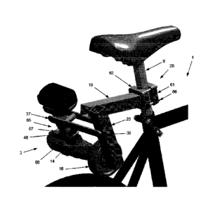
Figure 1 illustrates a typical pushbike 1 that has been converted into an
Ebike by clamping
articulated bracket 2 onto it. For clarity in this overview figure, drivetrain
details have been
omitted (spokes, pedals, chain, cables and other small hardware details). The
relevant parts of
the pushbike in this figure are its seat 6 and seatpost 9, which are
telescopically adjustable
inside its seat tube 4 by tightening seat clamp 5. Rear tire 11 mounted on
rear wheel 10 is
Page 12
Date Recue/Date Received 2020-06-09
frictionally propelled forward by rotational force applied by cordless drill
3. Handlebar 7 steers
the Ebike and is used to mount a throttle (not shown) that actuates the
trigger of drill 3.
Figure 2 is a large-scale view of Figure 1 illustrating left-side details of
the articulated bracket
and its associated mechanical components. The bracket's substantially
horizontal support-spar
member 19 is rigidly affixed at its forward end to seatpost 9 using integral
clamp 20. In this
example, clamp 20 is comprised of slotted bore 21 which is accurately sized to
slip over
seatpost 9; when pinch-bolt 22 is tightened the support-spar becomes securely
cantilevered
over the driven wheel 10 and its driven tire 11.
Several other configurations of a suitable clamp 20 will be evident to those
practiced in the art.
Figure 10 illustrates one example that uses a pair of V-notched clamping jaws
squeezed onto
seatpost 9 at its four corners by screws 22. Another variant of this spar-
clamping mechanism
(not illustrated) is to hinge the two clamping jaws along one side and tighten
them together on
the opposite side; ideally, by using a cam-clamp similar to the seat-clamp 5
shown in Figure 10.
In Figure 2, the cantilevered support-spar 19 includes a side-mounted pendulum
pivot-axle
located near its unsupported end. The pivot-axle shaft typically has a
fixation portion 24 (visible
inside its support-spar) and a bearing-axle portion 26 that projects from the
side of support-spar
19 to rotatably engage through its pivot-bearing 25 of pendulum-spar 23 (shown
in Figure 3).
The pendulum-spar also carries a bearing near its lower end that rotatably
supports a driveshaft
portion of friction-wheel 18. The lower bearing (35 in Figure 3) enables the
friction-wheel 18 to
rotate freely in the same plane as the pushbike's tire 11.
Support-spar 19 is shown clamped onto seatpost 9 at a height that is
appropriate for effective
Ebike propulsion. Instead of hanging vertically, pendulum-spar 23 is swung
forward due to its
captive friction-wheel 18 resting against the forward side of driven-tire 11.
In this configuration,
if friction-wheel 18 is counter-rotated to force forward rotation of tire 11,
the swinging contact
geometry forces the pendulous friction-wheel into to ever greater frictional
contact as the tire's
rolling resistance increases.
Note that, while Figure 1 shows a simplified pushbike having a rigid front
fork and a rigid rear
wheel ("hardtail") suspension, the traction of friction-wheel 18 onto driven
tire 11 will not be
significantly disturbed if it were mounted on a pushbike equipped with a
compliant wheel
suspension of one or both wheels. If a suspended driven wheel 10 hits a bump
in the road that
varies the distance between tire 11 and support-spar 19, then pendulum-spar 23
will simply
swing a bit further to compensate for the change in drivetrain geometry.
To impart propulsive force into friction-wheel 18, cordless drill 3 is affixed
by its chuck 12 onto a
driveshaft stub that projects from one side of the friction-wheel. The drill's
chuck is driven by its
internal motor 15, which is controlled by the variable-speed drill-trigger 14
located on the drill's
Page 13
Date Recue/Date Received 2020-06-09
handle portion 13. The cordless drill's battery 16 is typically removable so
that a freshly-
charged replacement battery can be swapped into handle 13 as needed.
To enable rider-controlled rotation of the drill's motor 15 and its attached
friction-wheel 18,
trigger 14 is mechanically actuated by a throttle control that is mounted on
or near the
pushbike's handlebar. A suitable throttle control (not illustrated) can be
comprised of a
conventional brake lever, repurposed to actuate the inner cable of jacketed
control cable 42.
Other suitable cable actuators can be fashioned using an off-the-shelf
gearshift lever or twist-
grip (again not illustrated). In this embodiment of a drill trigger-actuator,
cable 42 is routed from
the handlebar back to an off-the-shelf, 90 degree "brake cable noodle" that
anchors the cable's
outer casing and routes its inner control cable through an aperture in
pendulum-spar 23. The
drill's trigger is actuated by pushrod 44 that slides though the pendulum-spar
in response to the
control cable pulling on pushrod-actuator-bracket 49. Several other styles of
drill trigger-
actuator are shown in Figure 11.
While pushbike 1 is being propelled as an Ebike, the torque resistance of the
its driven wheel 10
will create an equal and opposite torque in friction-wheel 18. To prevent that
counter-torque
from spinning the entire drill (instead of inducing forward motion), anti-
torque arm 37 is
provided. Anti-torque arm 37 is an elongated rigid member affixed at one end
to pendulum-spar
23 and sized long enough to extend just past drill-handle 13, thereby blocking
it from rotating.
To prevent drill-housing rotation on both directions, anti-torque arm 37 will
typically provide
blockage onto both sides of drill-handle 13. One or more shim-pads 41 may be
provided so that
drill 3 can be easily affixed onto friction-wheel 18 without any side-play as
power is intermittently
applied.
Figure 3 is a large-scale view of Figure 1 illustrating right-side detail.
Articulated bracket 2 is
clamped to seatpost 9 and functions as described above. This right-side view
better illustrates
pendulum-spar 23; its upper bearing 25 and lower bearing 35 are typically
sealed ball bearings
that provide low friction and high rigidity as the pendulum swings from pivot-
axle 26 and the drill-
driven axle 34 of friction-wheel 18 turns to counter-rotate tire 11 forward.
Drill-trigger 14 is
actuated by pushrod 44; typically, via a cushioning pad 50 that spreads the
pressure and
maintains grip on the trigger. The inner control wire 48 of jacketed control
cable 42 is pulled
through aperture 47 in pendulum-spar 23, thereby forcing bracket 49 to slide
pushrod 44
through bearing-bore 45 to actuate trigger 14.
To achieve both structural robustness and bi-directional blockage of drill-
handle 13, torque-arm
37 may be configured as an H-shaped assembly as shown, thereby creating an
outboard
docking space into which the drill's pistol-grip handle slides as its chuck is
secured onto
protruding driveshaft stub of friction-wheel 18 (see Figure 4). Bridge support
39 imparts rigidity
to front and rear torque-blocking members 37 that are secured to the pendulum-
spar 23 with
fasteners 38 and to bridge-support 39 with fasteners 40. To adjust the H-
shaped torque-arm for
a sliding fit of the drill handle 13 of a particular drill, shim-washers may
be inserted between the
Page 14
Date Recue/Date Received 2020-06-09
arms 37 and their respective mating surfaces. If a particular drill has a slim
handle, adhesive
shim cushions 41 may be applied to the inner side of the docking space to
provide a snug fit.
Figure 4 illustrates two configurations of a friction-wheel suitable for being
a drill-driven
component of the drill-driven Ebike. Friction-wheel 18a is a monolithic
structure comprised of a
central core portion 36, an outer friction-surface portion 32, an axial
driveshaft-stub portion 33
and an axial bearing-support portion 34. In this example, the wheel's central
core portion 36
includes a series of optional holes that reduce its weight. Its friction
surface 32 is textured
rubber however various high-fiction surface finishes may be used; see knurled
surface 32 on
wheel 18B and the abrasive wheel-finish shown in Figure 11. Driveshaft stub 33
may have a
hexagonal cross-section to facilitate secure gripping in the drill's chuck.
The axial driveshaft's
bearing-support portion 34 extends far enough to fully seat within the
pendulum-spar's lower
bearing.
Friction-wheel 18b is an alternate embodiment of the friction-wheel; in this
case, an assembly
which includes an off-the shelf bicycle freewheel 27 (detailed in Figure 5).
The incorporated
freewheel acts as a one-way clutch that selectively transmits torque from the
driveshaft's input
stub 33 out to its friction surface 32.
Figure 5 is an exploded view of the freewheeling friction-wheel 18b shown in
Figure 4. It
illustrates a convenient and cost-effective way to add a one-way clutch that
allows friction-free
coasting and thereby improves the Ebike's energy efficiency. An off-the-shelf
"BMX" style
bicycle freewheel 27 is incorporated onto the assembly's central core portion
36 so that its
internal ratchet pawls apply power unidirectionally between driveshaft 33 and
friction surface 32.
The enlarged driveshaft adapter portion 29 includes an outer thread 58 that
matches the
standard hub-thread 59 inside freewheel 27 (this thread is typically 1.37" x
24 TPI). Once the
driveshaft and freewheel have been joined by screwing thread 58 into thread
59, the freewheel's
sprocket teeth 28 are placed flush against the friction-wheel's central core
portion 36 and
secured there by affixing retention-ring 30 against the opposite side of the
sprocket using a
plurality of retention screws 31. The retention screws are spaced-apart for
reaching through the
sprocket's teeth and into corresponding threaded holes in core-portion 36.
Figure 6 is an oblique view of an elongated embodiment of the friction-drive
mechanism that
includes a trailer hitch. Support-spar member 19 includes an extended portion
51 that reaches
past the location of the pendulum-spar's pivot-axle 26. The extension can
thereby provide
support for trailer-hitch 52, which in this example is simply a vertical bore
that is configured for
mating with a corresponding pin on the hitch mechanism of a cargo trailer when
needed.
Various other trailer-hitch configurations will be obvious to those practiced
in the art.
Figure 7 illustrates the extended support-spar embodiment of Figure 6 when it
is being used to
tow a trailer. In this example, trailer 53 is a folding dolly that includes a
swivelling pin style of
Page 15
Date Recue/Date Received 2020-06-09
hitch 54 that mates through the hitch aperture 52 near the rear end of support-
spar extension
51. Once the hitch pin 54 has been secured to the converted Ebike 1 (typically
using a cotter-
pin), its rider can transport a substantial load of cargo 55 with greater
ease.
Figure 8 illustrates another embodiment that enables pushbike 1 to haul extra
cargo. Support-
spar 19 and its trailer hitch extension 51 provide a stable foundation for
affixing one or more
cargo panniers 60. To enable drill 3 to rotate friction-wheel 18 at the end of
pendulum-spar 23,
the inboard wall of pannier 60 has appropriately-shaped apertures (not
visible) through which
the drill's chuck and the anti-torque arm operate. Panniers 60 may also
include lids (not
illustrated) that protects cargo from theft and exposure to the elements. The
pannier 60 that
houses the drill 3 may also be lined with a layer of sound-deadening material
to attenuate noise
from the drill which might otherwise detract from the rider's user experience.
Figure 9 illustrates the embodiment shown in Figure 1 after it has been
equipped with one or
more extra batteries that extend the Ebike's range. Pushbike 1 is fitted with
articulated bracket
2 such that its pendulously suspended friction-wheel 18 is counter-rotated by
drill 3 against tire
11 to propel the converted Ebike forward. Drill battery 16 is powering the
vehicle and when its
charge becomes depleted, one of freshly charged batteries 56 (mounted on
storage racks 56) is
swapped onto the drill to continue a long journey.
Figure 10 illustrates a light-weight embodiment similar to the one shown in
Figure 1. Support-
spar 19 is formed using a hollow tube to reduce weight. Pendulum-spar 23 is
also lightened, as
are its welded upper and lower bearing shells 63 and 64. Instead of throttling
the Ebike using a
pushrod style of drill-trigger actuator sliding through the pendulum-spar (as
shown in Figures 2
and 3), a "noose-style" of trigger actuator 65 is actuated by control lever 43
(shown conceptually
mounted onto a conceptual handlebar 7). Jacketed cable 42 routes its inner
actuating cable 48
via a standard bicycle "cable noodle" 46 such that it wraps around the trigger
and pistol-grip of
drill 3 and is secured into a noose that can be tightened to depress the
drill's trigger as needed
(see Figure 12 for details).
Seatpost clamp 20 is comprised of a pair of V-grooved jaws that adjust
automatically to grip
onto all of the common diameters used for seatpost 9. V-grooved jaw 62 is
welded to support-
spar member 19. V-grooved jaw 61 is corner-bolted to jaw 62 using threaded
fasteners 66;
when tightened, they force seatpost 9 to be firmly gripped along its 4
tangential contact lines.
Figure 11 illustrates another lightened embodiment that uses square tubes to
form the spars.
Support-spar 19 Is clamped to seatpost 9 as described above. Its rectangular
cross-sectional
shape facilitates fabrication of compact bearing fixations for hanging
pendulum-spar 23 and
friction-wheel 18. Noose-style drill-trigger actuator 65 is shown with an
optional sheath 68 that
flexibly distributes the force of inner control wire 48 as the noose tightens
onto drill-trigger 14.
Throttle-cable yoke 67 is used to form the noose (see detail in Figure 12).
Page 16
Date Recue/Date Received 2020-06-09
Figure 12 is a large-scale view of two drills (3a and 3b), each drill
illustrating one of two different
"noose-style" drill-trigger actuators (65a and 65b). Each these drill-trigger
actuators is
connected by inner control wire 48 and its outer control cable sheath 42 to a
cable-actuating
throttle located on the Ebike's handlebar (7 in Figures 1 or 10). In each
embodiment of this
style of trigger-actuator, an optional "cable-noodle" 46 may be used to guide
the inner control
through a sharp 90 degree bend towards trigger 14, while simultaneously
constraining the
ferrule-end of cable sheath 42. The cable-noodle wire-guide 46 is merely a
convenient, sharply-
curved extension of the outer cable 42; if it is omitted, then the coaxial
cable 42, 48 is simply
routed towards the trigger along a wider curve. Two styles of control cable-
yoke (67a and 67b
described below) may be used to form a noose that tightens around trigger 14
to variably control
the Ebike's speed.
Referring to the right-hand drill (3b), one end of cable-yoke 67b receives and
constrains the
ferrule end of outer cable sheath 42 (either directly or from its sharply
curved extension 46) .
The yoke's other end accepts and constrains a nipple formed on the end of
inner wire 48 (its
end-nipple 69 is shown about to be affixed through a slot in yoke 67a). Yoke
67b rests against
the drill's pistol-grip 13, thereby enabling wire 48 to wrap around trigger 14
and be locked into
the yoke's far end to form a noose that pulls on trigger 14 in response to
throttle actuation.
Similarly, on the left drill 3a, cable yoke 67a (a shorter version of 67b) is
positioned adjacent to
the side of pistol-grip 13. Inner control wire 48 exits one end of the compact
yoke, encircles the
pistol-grip 13 and is secured into a noose by seating its end-nipple 69
through a slotted yoke
aperture. Pulling inner wire 48 through its sheath 42, thereby tightens the
noose and actuates
the trigger.
These two examples of a noose-style trigger-actuator are shown with an
optional inner-wire low-
friction sleeve 68. If present, the wire-sleeve protects the drill's pistol-
grip and trigger from wire-
abrasion. It also reduces actuator friction that might otherwise prevent the
trigger from easily
springing back out when the throttle is released.
The configuration of both of the "noose-style" trigger actuators 65a and 65b
results in a halving
of the distance that the trigger will move in response to the distance that
the inner cable 48 is
pulled at the handlebar. This 2:1 ratio results in a throttle action that can
more easily make
small throttle adjustments. For example a trigger that has a range of 1/2"
will require the
actuator on the handlebar to pull the cable a full inch to achieve full
throttle. While that type of
slow throttle response is generally desirable, other configurations can be
implemented that
provide a faster throttle response (for example, Figure 3 illustrates a 1:1
throttle actuator).
Figure 13 illustrates a two-wheel drive embodiment of the invention that
includes dual
propulsion systems 2a and 2b; it can be used for increased power and better
traction on
slippery terrain. In this example, pushbike 1 is a "cruiser-style" bicycle
that includes a high-rise
handlebar 7, thereby providing user 80 with a more relaxed riding posture. To
further improve
Page 17
Date Recue/Date Received 2020-06-09
the Ebike's suitability for comfortable commuting, fenders 78 may be provided
however doing so
will prevent frictional contact between friction-wheel 18b and rear tire 11b.
To rectify the
fender's impediment to frictional contact, fender-aperture 79 is provided.
Handlebar stem 70 presents a tall enough vertical portion that clamp 20 can be
affixed onto
stem 70 in much the same manner as the clamp 20 is affixed onto seatpost 9 (as
shown in
Figure 10). If a particular handlebar stem does not provide sufficient
vertical tubing for affixing
the support-spar's clamp then its height can often be adjusted upward as
needed; in some
cases, an aftermarket "Stem Extender" will be needed to provides a good
clamping surface.
A second instance of the drill-powered propulsion system 2a can be fitted to
the front of a
suitably configured pushbike as described above for a rear-wheel drive 2b. The
rider's right
hand can actuate throttle 43a to regulate power output of drill 3a while a
left-hand throttle can
actuate the rear-mounted drill 3b. Note that, since handlebar 7, stem 70 and
front tire 11a are
all rigidly connected and turning in unison, the Ebike's steering performance
is virtually
unaffected by the front-mounted system 2a.
Note that the two-wheel drive version of Figure 13 (and 14) easily be
configured with only a
front-wheel drive propulsion system. Front-wheel drive on a pushbike raises
the possibility of
expanding the scope of the invention's applications to include FWD propulsion
of other types of
HPVs, such as tricycles (see Figure 21) and even kickbikes (see Figure 22).
Note also that, when configuring a front-wheel-drive system, extra care must
be taken to provide
a pendulum-spar that is long enough to prevent its friction-wheel 18 from
compressing tire 11 far
enough that its pendulum-spar can swing past its closest point of alignment
onto the center of
the wheel. If that geometric scenario were to occur then the friction-wheel
would be driven into
a violent "swing-through" collision against the pushbikes head-tube. Note too
that if the
pushbike has a telescopic front fork (not illustrated) then the pendulum-
spar's length must also
be long enough to prevent swing-through when the fork is fully extended.
Provided that the
pendulum-spar is long enough to prevent a swing-through failure, normal
telescopic action of a
front fork will be automatically accommodated as gravity causes the pendulum-
spar to swing
back and forth as it its friction-wheel responds to vertical motion of the
suspended front tire.
Figure 14 illustrates a simplified front-wheel drive embodiment 2b that
exploits the existing
support structure of a pushbike's handlebar 7 and stem 70. A dual-drive Ebike
is shown in
which the rear articulated bracket 2a includes pendulum-spar 23; it hangs on
and rotates about
the pivot axle 26, which is affixed to pushbike 1 via support-spar 23, clamp
20 and seatpost 9.
The front articulated bracket 2b is considerably simplified by utilizing the
pushbike's handlebar 7
to serve the same function as pivot axle 26 for suspending pendulum-spar 82.
Stem 70 also
serves a dual function; by supporting the handlebar/pivot axle 7, it
effectively acts as as support-
spar 19; together, these equivalent-functionality components provide a sturdy
pivot-axle with
Page 18
Date Recue/Date Received 2020-06-09
correct support geometry for enabling the rotatably attached pendulum-spar to
drive the front
wheel (see Figure 15 for details).
Note that the rear cordless drill 3a is mounted onto the pushbike's left side
while the front
cordless drill 3b is mounted onto its right side. The example serves to
illustrate that the Drill-
powered Ebike can be configured for either left-side drive or right-side
drive; the main difference
in a mirror-imaged system is that drill's direction of rotation is reversed.
To advance Ebike 1
forward, drill 3a is set to rotate clockwise while drill 3b is set to rotate
counterclockwise.
Figure 15 is a large-scale view of the front-wheel drive embodiment 2b shown
in Figure 14.
Stem 70 includes a forward-reaching portion that clamps onto the middle of
handlebar 7,
thereby presenting two transverse handlebar portions adjacent to the left and
right sides of stem
70; these handlebar portions can serve as a pivot-axle for a suitably
configured pendulum-spar.
To do so, pendulum-spar 82 includes a slip-bearing clamp 83 at or near its
upper end that is
configured for rotational engagement onto handlebar 7 adjacent to stem 70,
thereby eliminating
the need for a purpose-built support-spar 19 and pivot-axle 26 (shown in the
rear-wheel-drive
portion of Figure 14).
In simplified, front-wheel-drive-only embodiment of Figure 15, the lower end
of pendulum-spar
82 is configured as described above: i.e., it carries an anti-friction bearing
that supports the axle
of friction-wheel 18b so that the high-friction rim can be counter-rotated
against front wheel 11b
by drill 3b. Since bearing-clamp 83 only experiences slight rotational forces,
it does not require
the kind of high-speed anti-friction bearing needed to sustain propulsive
force through friction-
wheel 18b. The slip-bearing clamp 83 shown in Figure 15 is the most basic
embodiment: it
consists simply of an accurately bored hole through pendulum-spar 82, that
closely matches the
diameter of the thickened, central portion of handlebar 7 (typically 25.4 mm
or 31.8 mm). In
some cases, the user's handlebar will not have a suitable amount of straight
and exposed
central tubing, in which case the Ebike conversion process will entail fitting
one with an
acceptable tube profile.
The illustrated slip-clamp bearing 83 enables the upper end of pendulum-spar
82 to be fitted
over the handlebar from one end and slide into place against stem 70, where it
acts as a plain
bearing onto the handlebar, thereby converting the handlebar into a pivot-axle
for pendulum-
spar 82. To prevent the pendulum-spar 82 from drifting away from the stem 70
and upsetting
the traction of its friction-wheel onto the tire, a small locking protrusion
84 is typically affixed to
the handlebar, adjacent to the slip-bearing's opposite side (not visible). In
a more sophisticated
embodiment, an adjustable-friction slip-bearing clamp (not illustrated) might
be fashioned in a
manner similar to the V-grooved clamp 20 (shown in Figure 14) that is used to
affix support-spar
19 to seatpost 9. If an adjustable slip-clamp 83 is fashioned, it preferably
includes a plastic
lining that slides easily over the handlebar as the pendulum-spar swings
slightly back and forth.
This will enable the user to eliminate any side-play of the friction-wheel
while still allowing the
pendulum-spar to easily swing slightly back and forth as needed.
Page 19
Date Recue/Date Received 2020-06-09
Another embodiment of a suitable slip-clamp configuration (not illustrated)
combines elements
of the front-wheel-drive shown in Figure 13 with the one shown here in Figure
15. Instead of
utilizing the handlebar tube directly as a pivot axle for rotating the
pendulum-spar 82, a compact
hinge-half fixture is clamped tightly onto the handlebar, adjacent to stem 70.
The upper end of
the pendulum-spar includes a machined hinge-half that engages into its mate on
the handlebar
and a hinge-pin secures the two halves together. Depending on the stem and
handlebar
configuration of the pushbike being converted to an Ebike, the hinged slip-
clamp embodiment
may be somewhat easier to install than the simplest one described above. An
added advantage
is that, if the hinge is formed at some distance from its handlebar clamp
(essentially forming a
laterally-offset support-spar), rotating this elongated clamp to different
angles about the
handlebar will adjust the effective overall distance to the friction-wheel and
thereby provide a
useful way to fit the hinged pendulum-spar onto various sized pushbikes. The
added geometric
degree of freedom and its attendant adjustability may also be useful for
repositioning the
pendulum-spar to prevent interference with the pushbike's brake control levers
and cables.
Trigger actuation: The FWD (front-wheel drive) configuration shown in Figures
14 and 15
reveals yet another way that the trigger of cordless drill 3 can be remotely
actuated from
handlebar 7. The trigger actuators described further above (for actuating both
FWD and RWD
embodiments) depend on use of a coaxial control cable; the actuator shown in
Figure 3 uses a
remote, cable-operated pushrod 44 to depress trigger 14. The actuators shown
in Figure 12
use a remote, cable-operated noose to depress the trigger. Since the FWD
pendulum-spar 82
swings directly from (or near) the handlebar, the potential exists for
implementing a short,
manually-actuated mechanical linkage directly onto the trigger, thereby
eliminating the need for
a remote coaxial control cable.
To implement this type of FWD-specific trigger-actuator, the pushrod (44 shown
in Figure 3)
may be reconfigured for direct actuation from the handlebar via a "rocker-
actuator" member (not
illustrated). The rocker-actuator extends from the pushrod-end up the pendulum-
spar, over a
fulcrum-bearing that retains the rocker in place; the rocker terminates at its
upper end with a
suitably formed handle portion for actuation by the rider's throttle-hand.
Alternatively, a FWD-
specific trigger-actuator might be fashioned using a single "trigger-lever"
(also not illustrated).
The trigger-lever is also a rocker-style member; at one end it is bent to
impinge directly against
the drill's trigger and at it other end it is bent to provide a hand-grip that
is conveniently-near the
handlebar. A pivot bearing affixed to the anti-torque arm (possibly coincident
with the anti-
torque arm spacer 39 of Figure 3) journals and retains the trigger lever to
act as a fulcrum,
thereby enabling the rider to manually actuate the lever's upper end to
depress the spring-
loaded drill-trigger at the other. To enable the trigger-lever to fit various
handlebar
configurations, it is typically made of stiff but bendable material such as
aluminum, thereby
enabling the rider to fine-tune its bent shape for optimal actuation of their
drill.
Page 20
Date Recue/Date Received 2020-06-09
Figure 16 illustrates an embodiment that conforms to the legal requirement in
some jurisdictions
that an Ebike's assist mechanism only be operable while its rider is
pedalling. In order to
comply with such legislation, instead of relying on a cordless drill for its
electromotive propulsive
force, this embodiment utilizes a standard off-the-shelf electric motor 71 and
couples it directly
onto the driveshaft of friction-wheel 18. A compact anti-torque arm 72 bridges
over the friction-
wheel to anchor the motor to the pendulum-spar, thereby enabling the use of
separate
components that ensure the Ebike meets local regulations for rider-
participation and top-speed.
To insure that the converted Ebike meets Class 1, 2 and 3 requirements (the
class definitions
are summarized further above), motor controller 73 is electrically connected
to motor 71, battery
56, electronic throttle 78, pedal-cadence sensor 74 and wheel speed-sensor 76.
Wheel-speed
sensor 76 is activated by a magnet 77 mounted on a wheel 10 and pedal-cadence
sensor 74 is
activated by crank-mounted magnet 75. Throttle 78 is typically a rheostatic
twist-grip mounted
on handlebar 7. The two speed sensors and the throttle are typically hardwired
to the motor
controller; alternatively, the two sensors may transfer data wirelessly to
simplify installation. The
motor controller includes logic circuitry that enables it to use the three
electrical signals in
accordance with the local speed and rider-participation regulations. The
computed real-time
power application data is used to regulate the high-power current flow from
battery 56 to motor
71. A smartphone may be affixed onto handlebar 7 to display such as trip
information and
battery charge condition (not illustrated).
Battery 56 is typically the same as used to power a cordless tool (such as the
drill 3 shown in
Figure 14). Battery carrier 57 facilitates mounting multiple batteries and can
include circuitry for
joining them in series to produce higher voltage. For example, a popular
cordless tool battery
configuration provides 18 volts; if carrier 57 connects them in series then
motor 71 may be
chosen from one of the many 36 volt off-the-shelf products on the market.
Additional batteries
may be mounted on the exterior of support-spar 19 or frame-mounted as shown in
Figure 9.
There may be sufficient room inside of hollow support-spar 19 to neatly
contain the electronic
components of motor controller 73, this compact electronics-packaging strategy
is particularly
suitable when using the extended-spar shown in Figure 8.
Figure 17 is a large-scale view of Figure 16 showing details of the components
used for
upgrading the drill-driven (Class 2 only) embodiment of Figure 11 to a fully-
compliant (Class 1, 2
and 3) Ebike. Seatpost-clamp 20, support-spar 19, pendulum-spar 23 and
friction-wheel 18 are
major structural components that are common to both the compliant and non-
compliant
embodiments. This presents the opportunity for a pushbike owner to start off
by fitting the most
basic drill-driven Ebike kit to power their converted pushbike. Once they have
tried Ebiking with
a drill-powered (Class 1) version, they can later choose to upgrade it to
either Class 1 or Class 3
operation. To do so, they used pre-drilled mounting holes in the basic support-
spar and
pendulum spar to add components. Motor 71 is added to replace the drill (using
an adapter-
collar). The large torque-arm 37 shown in Figure 11 is removed and replaced by
a compact
torque-arm 72. Motor-controller 73 is then bolted on, together with its
connected speed sensor,
Page 21
Date Recue/Date Received 2020-06-09
cadence sensor and throttle. Swappable batteries 56 are also mounted and wired
to complete
the conversion.
Figure 18 illustrates a two-wheel-drive embodiment that also complies with
Class 1, 2 and 3
Ebike requirements. It resembles the embodiment shown in Figures 13 and 14
except that the
cordless drills 3a and 3b have been replaced by separate electric motors 71a
and 71b.
Handlebar throttles 43a and 43b control electromotive power being applied to
front and rear
tires lla and llb using shared electronic components (motor-controller 73 and
its associated
batteries, wiring and speed sensors).
Figure 19 illustrates the front-wheel- drive propulsion system 2b of Figure 18
in which the
pushbike's handlebar 7 serves as the upper pivot-axle that bearing 83 of
pendulum-spar swings
on. The forward-reaching portion of stem 70 serves the same function as the
support-spar 19
shown in Figure 13. This front-wheel drive system may be used as a stand alone
system
provided the shared electronic components shown in Figure 18 are included (its
batteries,
sensors and motor controller). To provide a well-configured handlebar for
engagement with
slip-bearing clamp 83, a precision-machined aftermarket handlebar may be
provided for
retrofitting to pushbike 1.
Figure 20 illustrates a front-wheel-drive embodiment similar to the one shown
in Figure 19. In
this embodiment, hub motor 85 serves the same function as drill 3b in Figure
15 or the electric
motor 71b shown in Figure 19. Unlike electric motor 71b, which requires that
an anti-torque arm
72b constrain the motor housing from turning so that its output shaft is free
to rotate the
attached friction-wheel 18b, the central shaft of hub motor 85 is firmly
gripped in a clamping
bore located near the lower end of pendulum-spar 82. The hub motor's internal
winding's can
thereby exert electromotive force to turn the motor's high-friction rim 32.
The upper slip-bearing
clamp 83 enables the pendulous motor 85 and friction-surface 32 to engage onto
and
fractionally drive tire 11. This configuration eliminates the need for a
separate anti-torque arm
and results in a generally more compact device.
The illustrated hub motor 85 has a central shaft that projects from only one
of its two side (in this
case, the far side) however many suitable hub motors have grippable shaft
portions on both
sides, thereby providing a symmetrical load distribution. If a symmetrical hub
motor is being
used, then a second pendulum-spar (not illustrated) may be added to handlebar
7 to grip the
motor symmetrically (with a spar on each side of the handlebar stem).
Similarly, pendulum-spar
configurations such as those shown in Figures 1 and 13, can be reconfigured
for symmetrically
carrying a hub motor (instead of a drill-driven friction-wheel). To do so, a
forked pendulum-spar
(not illustrated) hangs centrally from the support-spar's outer end; a
centrally located hinge joins
the two spars and each side of the swinging fork grips onto a side of the hub
motor's shaft.
The pendulum-spar 82 is typically hollow and therefore able to house the
electronic motor
controller 73 that regulates the output of motor 85 in response to electronic
throttle 43. If a
Page 22
Date Recue/Date Received 2020-06-09
second pendulum-spar is present, as described above, then it will add to the
available space for
containing electronic components so batteries may also be stored therein.
Preferably,
swappable power-tool batteries 56 are carried on the pendulum-spar in battery
cradles 57.
Slip-bearing clamp 83 may be a simple bore fitted over handlebar 7 as shown.
Alternatively, a
quick-release hinged opening (not shown) enables the user to quickly detach
the entire
propulsion system 2 from handlebar 7 of pushbike 1, thereby enabling the Ebike
to be parked
while its propulsion system is carried away by the user for safekeeping or for
battery charging.
To reactivate the Ebike, the quick-release slip-bearing clamp is refitted to
handlebar 7 and the
control wire contact from throttle 43 is reattached to controller 73.
Note that, since the hub motor 85 fully occupies all of the space bounded by
its high-friction rim
32, no room is available to incorporate a freewheel as shown in Figure 5. This
lack of a
mechanical freewheel would render the drivetrain inefficient when coasting
(due to the magnetic
drag of the motor). To counteract that energy-loss problem, the motor-
controller's electronic
circuit and algorithm is used to provide just enough power to match the speed
of friction-surface
32 to its driven tire 11 when throttle 43 is shut off, thereby minimizing any
drag effects during
coasting or while the rider is pedalling with the throttle closed.
Figure 21 illustrates a "Halfbike" tricycle 86 that has been converted into an
electric-assist
vehicle by adding a friction-drive mechanism 2 of the present invention. The
unmodified
Halfbike TM (see US D774, 969 S) is tricycle-style HPV that is steered by its
user transferring
their body weight from side to side, thereby causing the spring-loaded
steering truck 87 to pivot
left or right; its steering operates in much the same was as that of a
skateboard (see videos of it
at www.halfbikes.com). Halfbike 86 is comprised of a tall handlebar stem 88
joined to a pair of
frame rails 91 by pivot clamps 89 and locking clamps 90, thereby enabling
handlebar 7 to be
selectively folded down towards the tricycle's rear wheels for compact storage
or transport. A
conventional pedal-crank drivetrain 92 enables a standing rider to propel
wheel 10 forward.
To convert the illustrated pushbike 86 into an electric-assist vehicle, drill-
driven friction-drive
mechanism 2 is affixed to the HPV's handlebar stem 88 using a lockable spar-
pivot fixture 97
see detail in Figure 22). Once drive unit 2 has been mounted with correct
orientation of its
articulated bracket (19 and 23), drill 3 rotates friction-wheel 18 against
tire 11 to propel the
tricycle's front wheel forward. The trigger of drill 3 is actuated by throttle
lever 43 acting through
coaxial cables 42 and 48 (partially drawn). Brake lever 95 similarly actuates
a drum or caliper-
type brake to stop the vehicle as needed. An optional rear footboard 94 may be
provided to
help the user counterbalance the forward-capsizing moment experienced under
heavy braking.
A second footboard 92 may provided to enable the user to rest both of their
feet off of the pedal-
crank while the vehicle is cruising solely under electric power.
Figure 22 is a larger-scale view of the drill-powered HPV shown in Figure 21.
To enable the
friction-drive's support-spar 19 to be affixed to folding handlebar stem 88,
pivot-fixture 98 is
Page 23
Date Recue/Date Received 2020-06-09
provided to join the stem's left and right sides together by a shaft, about
which the forward end
of support-spar 19 is journaled to form a rotatably and slideably articulated
joint. Any movement
of this articulated joint during drill-powered operation would result in the
loss of traction between
friction-wheel 18 and tire 11. To prevent that malfunction from occurring,
locking-pin 97 fits
snugly through aligned holes in the spar and shaft, thereby immobilizing the
support-spar 19
with respect to stem 88 and tire 11 (in much the same manner as clamp 20
immobilizes
support-spar 19 with respect to stem 70 and tire 11 in Figure 13).
As described above (for non-folding embodiments), the forward inclination and
fixed geometry
of the freely-swinging pendulum-spar 23 enables it to leverage the rotational
force from drill-
driven friction-wheel 18 onto tire 11 and thereby drive it forward. Drill 3 is
prevented from being
counter-rotated by anti-torque arm 37 and its trigger 14 is throttled by
actuator 65, which forms a
noose of inner control wire 48 that can be tightened by squeezing the
vehicle's handlebar-
mounted throttle lever (see Figure 12 and 43 in Figure 21).
While the drill-powered propulsion mechanism 2 is locked in its operative
configuration, it will
interfere with the Halfbike's folding function. The interference problem is
due to the fact that,
once the handlebar stem is unlocked for pivoting, its normal folding action
will be arrested when
the fixed support-spar 19 collides with tire 11. To alleviate that problem and
permit full folding,
locking-pin 97 is withdrawn so that support-spar 19 becomes free to rotate
upwards around
pivot-fixture 98. Friction-wheel 18 will thereby become free to roll up and
over the top of tire 11
so that both the liberated support-spar 19 and its swinging pendulum 23 can
articulate towards
the horizontal as handlebar stem 88 is folded down fully into its compact
storage configuration.
Figure 23 illustrates a kickbike-style of HPV that has been converted into an
Electric Vehicle by
adding the present invention as a kit to propel its front wheel forward. The
drill-driven friction-
drive unit 2 is virtually identical to the one shown driving the front wheel
in Figure 13. The one
difference in this example is that the length of support-spar 19 has been
shortened to
accommodate the smaller diameter of tire 11. Pendulum-spar 23 has not needed
to be
shortened because clamp 20 has a long range of vertical travel on handlebar
stem 70.
Propulsion from drill 3 and friction-wheel 18 enable a rider standing on
footboard 93 to advance
with only a minimal requirement to assist propulsion by kicking their electric-
assist HPV forward.
Figure 24 illustrates a foldable, three-wheeled electric-assist HPV powered by
the friction-drive
mechanism of the present invention. To configure this embodiment, the hybrid-
powered HPV
shown in Figure 21 is simplified by replacing its pedal-crank drivetrain (92)
by one or more
footboards 93, 94. Without its pedal-crank drivetrain, this stripped-down
version of the Halfbike
might conceivably be used as a tricycle-style Kickbike however adding the
drill-driven friction-
drive mechanism 2 greatly improves its performance and usability.
Since the pedal-crank is absent, footboard 93 can be made wide enough for the
rider to stand
on with both feet. The lack of a pedal-crank drivetrain also facilitates
locating a caliper brake
Page 24
Date Recue/Date Received 2020-06-09
underneath the footboard (not illustrated). During hard braking or a steep
decent, the rider may
step rearward onto footboard 94, thereby reducing the risk of the vehicle
accidentally tipping
forward. The rider may also choose to move one or both fee to the rear
footboard simply for a
change in ergonomic comfort. The large rear footboard may also be used to
carry a passenger
or to strap on a small load of cargo. Footboard 94 may also incorporate an
aperture or
projecting fixture that acts as a hitch capable of pulling a suitably
configured trailer (somewhat
similar to the towing configuration shown in Figure 7).
Note that this non-pedal-assisted embodiment may require extra electromotive
power to propel
it under heavy loads; the cordless drill 3 chosen to turn friction-wheel 18
should therefore be a
high-powered industrial drill, preferably one with a wide choice of gear
ratios. For example,
DewaltTM makes a brushless 3-speed cordless drill and Hilti TM makes a
brushless 4-speed
cordless drill; mounting either of those powerful drills will enable a rider
who encounters difficulty
climbing a hill to switch their drill to a lower gear ratio and thereby
overcome the temporary
overloading problem. To deal with the extra battery drain, auxiliary battery
packs 56 may be
affixed to frame 91, thereby enabling spent batteries to be swapped onto the
drill as needed.
Note also that both the legally-compliant embodiment shown in Figure 19 and
the hub-motor
embodiment shown in Figure 20 may be used in place of the drill-driven
embodiments shown in
Figures 21 to 24.
The foregoing has constituted a description of specific embodiments showing
how the invention
may be applied and put into use. These embodiments are only exemplary. The
invention in its
broadest, and more specific aspects, is further described and defined in the
claims which now
follow. These claims, and the language used therein, are to be understood in
terms of the
variants of the invention which have been described. They are not to be
restricted to such
variants but are to be read as covering the full scope of the invention as is
implicit within the
invention and the disclosure that has been provided herein. It is appreciated
that certain
features of the invention, which are, for clarity, described in the context of
separate
embodiments, may also be provided in combination in a single embodiment.
Conversely,
various features of the invention that are, for brevity, described in the
context of a single
embodiment, may also be provided separately or in any suitable sub-
combination.
Page 25
Date Recue/Date Received 2020-06-09