Note: Descriptions are shown in the official language in which they were submitted.
Headband Arrangement and Welding Helmet Equipped with the Same
FIELD
The present application generally relates to a headband arrangement and a
welding helmet,
especially an auto-darkening welding helmet, equipped with the headband
arrangement.
BACKGROUND
Welding helmets have become essential devices for protecting welders on
welding sites.
A welding helmet generally comprises a helmet shell and a headband arrangement
disposed in the helmet shell. A protection sheet is mounted on the helmet
shell to protect
a welder's eyes. The headband arrangement is connected to the helmet shell and
can be
used to be directly worn on the welder's head.
A helmet mounting structure provided at a side of each ear of the welder is
used to connect
the headband arrangement to the helmet shell. If the welder can adjust the
distance
between his/her eyes and the protection sheet in case that the welding helmet
is worn, it
will be more helpful to protect the welder's eyes.
Further, in a conventional headband arrangement, no sufficient flexible
cushion structure
is provided at a location of protecting the back of the welder's head, such
that the same
headband arrangement cannot enable wearers whose heads have different shapes
(especially the back of the head) to feel comfortable enough, which may
indirectly impact
the wearer's work efficiency.
SUMMARY OF THE INVENTION
The present application is mainly aimed at providing an improved headband
arrangement
for the welding helmet, such that after the headband arrangement is worn on
the wearer's
head, it is easy for him/her to adjust the position of the headband
35
4015828
Date Recue/Date Received 2020-06-10
arrangement relative to the welding helmet, and the worn headband arrangement
can be
more fitted for the shape of different wearers' heads and enable them to feel
more
comfortable.
In one aspect of the present application, a headband arrangement for a welding
helmet is
provided, the headband arrangement comprising:
a fixed attachment structure;
a helmet mounting structure cooperating with the attachment structure, wherein
at least
two stopping positions are defined longitudinally between the attachment
structure and
the helmet mounting structure, the helmet mounting structure is selectively
switchable
between an unlocking state and a locking state, wherein in the unlocking
state, the helmet
mounting structure is slidable between the stopping positions relative to the
attachment
structure, and wherein in the locking state, the helmet mounting structure can
be locked
to one of the stopping positions relative to the attachment structure and can
be held there
by a magnetic force generated between a pair of magnetic parts.
One key of the present application is to maintain the helmet mounting
structure of the
headband arrangement in its locking state by the magnetic force generated
between the
pair of magnetic parts.
Optionally, the helmet mounting structure comprises a lockable component which
is
mounted such that it is pivotable about a pivotal shaft in the helmet mounting
structure,
the pair of magnetic parts comprise a first magnetic part secured on the
lockable
component and a second magnetic part secured on the helmet mounting structure
or the
attachment structure; the helmet mounting structure can be switched between
the
unlocking state and the locking state by rotating the lockable component, and
in the
locking state, the helmet mounting structure is kept to be locked by a
magnetic attractive
or repulsive force generated between the first and second magnetic parts.
Optionally, the first magnetic part has a first magnetic side, and the second
magnetic part
has a second magnetic side;
in case that the first magnetic side has the same magnetic polarity as the
second
magnetic side, the first and second magnetic parts are arranged such that as
the lockable
component is pivoted from the locking state to the unlocking state, the first
magnetic side
approaches the second magnetic side; or
2
4015828
Date Recue/Date Received 2020-06-10
in case that the first magnetic side has a magnetic polarity different than
the second
magnetic side, the first and second magnetic parts are arranged such that as
the lockable
component is pivoted from the locking state to the unlocking state, the first
magnetic side
departs from the second magnetic side.
Optionally, the lockable component has a tongue, the stopping positions are
defined by
several location holes formed in the attachment structure, the tongue enters
one of the
location holes in the locking state, and the tongue leaves the location hole
in the unlocking
state to allow the helmet mounting structure to be longitudinally slidable.
Optionally, the helmet mounting structure has a bracket in which a socket is
defined, and
the pivotal shaft and the lockable component are disposed in the socket.
Optionally, the second magnetic part is disposed in the socket.
Optionally, the attachment structure has a location plate, the location holes
are provided
in the location plate, and a rail is provided in the location plate to guide
the helmet
mounting structure.
Optionally, the pivotal shaft is substantially parallel to the location plate.
Optionally, the second magnetic side of the second magnetic part is
substantially parallel
to the location plate.
Optionally, the lockable component has a handle which is exposed out of an
opening of
the socket to be accessible.
Optionally, an inserting component is received in the socket, the second
magnetic part is
securely provided in the inserting component, and the inserting component has
an edge
which defines a scope of moving of the handle in the opening of the socket.
In an alternative embodiment, the helmet mounting structure comprises a
lockable
component which is linearly movable in the helmet mounting structure, the pair
of
magnetic parts comprise a first magnetic part secured on the lockable
component and a
second magnetic part secured on the helmet mounting structure or the
attachment
3
4015828
Date Recue/Date Received 2020-06-10
structure; the helmet mounting structure can be switched between the unlocking
state and
the locking state by linearly moving the lockable component, and in the
locking state, the
helmet mounting structure is kept to be locked by a magnetic repulsive force
generated
between the first and second magnetic parts.
Optionally, the lockable component can be moved in a direction substantially
perpendicular to a moving direction of the helmet mounting structure.
Optionally, the first and second magnetic parts are arranged such that they
approach each
other as the helmet mounting structure is being changed from the locking state
to the
unlocking state.
Optionally, the lockable component has a tongue, an elongated slot is formed
in the
attachment structure, the tongue protrudes into the slot, and the stopping
positions are
defined by several notches formed at a side of the slot and in communication
with the slot,
and wherein in the locking state, the tongue enters one of the notches, and in
the unlocking
state, the tongue leaves the notch to allow the helmet mounting structure to
be
longitudinally slidable.
Optionally, in the unlocking state, the tongue is longitudinally movable in
the slot.
Optionally, the helmet mounting structure has a bracket in which a socket is
defined, and
the lockable component and the second magnetic part are disposed in the
socket.
In an alternative embodiment the helmet mounting structure comprises a
lockable
component which is linearly movable in the helmet mounting structure, the pair
of
magnetic parts are disposed such that they are linearly movable in the helmet
mounting
structure, the pair of magnetic parts can be moved in a direction
substantially
perpendicular to a moving direction of the lockable component and parallel to
a moving
direction of the helmet mounting structure, the movement of the pair of
magnetic parts is
in association with the movement of the lockable component such that the
helmet
mounting structure can be switched between the unlocking state and the locking
state,
and in the locking state, the helmet mounting structure is kept to be locked
by a magnetic
repulsive force generated between the first and second magnetic parts.
4
4015828
Date Recue/Date Received 2020-06-10
Optionally, the lockable component has a tongue, the stopping positions are
defined by
several location holes formed in the attachment structure, the tongue enters
one of the
location holes in the locking state, and the tongue leaves the location hole
in the unlocking
state to allow the helmet mounting structure to be longitudinally slidable.
Optionally, the helmet mounting structure comprises a first key part and a
second key part,
the pair of magnetic parts comprise a first magnetic part embedded in the
first key part
and a second magnetic part embedded in the second key part, and the first and
second
magnetic parts approach each other as the helmet mounting structure is being
changed
from the locking state to the unlocking state.
Optionally, at least one of the first and second key parts is provided with a
rod portion by
which the lockable component can be driven to move.
Optionally, the rod portion has a linear section and an arc-shaped section,
and the rod
portion is inserted through a through-hole formed in the lockable component
such that
the rod portion can be moved substantially perpendicularly to the moving
direction of the
lockable component so as to pass through the through-hole.
Optionally, when the arc-shaped section of the rod portion passes through the
through-
hole, the lockable component is driven to move.
Optionally, when the crest of the arc-shaped section is located in the through-
hole, the
helmet mounting structure is in the unlocking state.
Optionally, the first and/or second magnetic part is a permanent magnet.
In another aspect of the present application, a headband arrangement for a
welding helmet
is provided, the headband arrangement comprising a band part for attaching at
or adjacent
to the back of a user's head, wherein the band part is provided with a sheath
for adjusting
the band part's length, a cushion structure is installed at a side of the
sheath facing the
back of the user's head, and wherein between the side of the sheath facing the
back of the
user's head and the cushion structure, two pivotal pins are provided adjacent
to two lateral
edges of the sheath such that the cushion structure can be pivoted about the
two pivotal
pins relative to the sheath.
5
4015828
Date Recue/Date Received 2020-06-10
Optionally, the cushion structure comprises two loop sections which are
connected by a
connection section, and each loop section has a support rib on which the
pivotal pin is
formed.
Optionally, two lugs are provided on the side of the sheath facing the back of
the user's
head, each lug is formed with a hole, the holes of the lugs are substantially
coaxial with
each other or their central axes include a small angle, and a respective
pivotal pin can be
inserted in a respective hole such that the cushion structure can be pivoted
relative to the
sheath.
Optionally, the cushion structure comprises two loop sections which are
connected by a
connection section, each loop section has a support rib for the pivotal pin, a
hole is formed
in each support rib, the holes of the support ribs are substantially coaxial
with each other
or their central axes include a small angle, two lugs are provided on the side
of the sheath
facing the back of the user's head, the pivotal pines are formed on the lugs
respectively,
and a respective pivotal pin can be inserted in a respective hole such that
the cushion
structure can be pivoted relative to the sheath.
Optionally, the pivotal pins are inserted into the holes by bending the
cushion structure
from its lateral edges towards its center.
Optionally, a sweat-absorbing pad is provided on a side of the cushion
structure facing
the back of the user's head.
In another aspect of the present application, a welding helmet equipped with
said
headband arrangement is provided.
Optionally, said welding helmet is an auto-darkness welding helmet.
BRIEF DESCRIPTION OF THE DRAWINGS
As a part of the description and in order to provide further explanation of
the present
invent, the drawings illustrate preferred embodiments of the present
invention, and
together with the description are used to explain the principle of the present
invention. In
6
4015828
Date Recue/Date Received 2020-06-10
the drawings:
Fig. 1 is a perspective view schematically illustrating a headband arrangement
for a
welding helmet according to an embodiment of the present application;
Fig. 2 is an exploded and perspective view schematically illustrating a
bracket of a helmet
mounting structure of the headband arrangement of Fig. 1;
Figs. 3a and 3b schematically illustrate that the helmet mounting structure is
in a locking
state and an unlocking states respectively;
Figs. 4a and 4b schematically illustrate how to adjust the helmet mounting
structure
relative to the headband arrangement;
Figs. 5a and 5b schematically illustrate that a helmet mounting structure
according to
another embodiment of the present application is in the locking state and the
unlocking
state respectively;
Fig. 6a schematically illustrates a partial and perspective view of a headband
arrangement
according to another embodiment of the present application, wherein the
headband
arrangement's helmet mounting structure is in the locking state;
Fig. 6b schematically illustrates that the helmet mounting structure of Fig.
6a is in the
unlocking state;
Fig. 7 schematically illustrates a partial and perspective view of a headband
arrangement
according to another embodiment of the present application;
Fig. 8a is a partially cross-sectional and perspective view schematically
showing a helmet
mounting structure for the headband arrangement of Fig. 7;
Figs. 8b and 8c schematically illustrate that the helmet mounting structure of
Fig. 7 is in
the locking state and the unlocking state respectively;
Fig. 9 schematically illustrates a cushion structure according to one
embodiment of the
7
4015828
Date Recue/Date Received 2020-06-10
present application, which is located on a rear sheath of the headband
arrangement; and
Fig. 10 schematically illustrates the cushion structure of Fig. 5 in two
different pivoted
states.
DETAILED DESCRIPTION OF EMBODIMENTS
In the drawings of the present application, the same or similar features are
represented by
the same reference numerals.
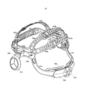
Fig. 1 is a perspective view schematically illustrating a headband arrangement
10 for a
welding helmet (not shown) according to an embodiment of the present
application. It is
noted that in the context of the present application, the cited welding helmet
can be also
used to refer to an auto-darkening welding helmet. Generally, the welding
helmet
comprises a helmet shell and the headband arrangement 10 disposed within the
helmet
shell. In order to protect eyes of a wearer who will do welding work, a
protection sheet is
mounted on the helmet shell.
The headband arrangement 10 can be made of a plastic material. As shown in
Fig. 1, the
headband arrangement comprises several band parts 101, 102a, 102b, 103a, 103b,
104a,
104b, 105a, and 105b. The band part 101 is used to bear against the wearer's
forehead.
The band parts 102a, 102b, 103a, 103b, 104a, and 104b are used to bear against
the top
of the wearer's head. The band parts 105a and 105b are used to attach at or
around the
back of the wearer's head.
The headband arrangement 10 also comprises two lateral band parts 110a and
110b. The
band parts 103a, 104a, and 105a are provided to extend integrally from the
lateral band
part 110a. The band parts 103b, 104b, and 105b are provided to extend
integrally from
the lateral band part 110b. For instance, each of pairs of the band parts 102a
and 102b,
103a and 103b, and 104a and 104b are provided with an engaging structure
therebetween
by which the tightness of the headband arrangement 10 to be worn can be
adjusted.
Further, each of the band parts 105a and 105b is provided with a toothed slot
at one end.
The ends of the two band parts can be inserted into a rear sheath 200 (Fig. 9)
made of a
plastic material in such a way that the ends are partly overlapped. A rotary
knob 210 is
8
4015828
Date Recue/Date Received 2020-06-10
rotatably installed on the rear sheath 200. A gear cooperating with the rotary
knob 210 is
provided in the rear sheath 200. The gear also engages with the toothed slots
of the band
parts 105a and 105b such that by positively or negatively rotating the knob
210, the two
band parts 105a and 105b can be displaced with respect to each other to adjust
the
tightness of the headband arrangement 10.
The band parts 101, 102a, and 102b are pivotably connected to the lateral band
parts 110a
and 110b respectively such that when the headband arrangement 10 is worn by
the wearer,
the band parts 101, 102a, and 102b are more fitted for the forehead of wearers
whose
heads have different shapes.
An attachment structure 500 is provided on each of the lateral band parts 110a
and 110b
of the headband arrangement 10, and is used to cooperate with a respective
helmet
mounting structure 300. For instance, the lateral band part can be integrally
formed with
the attachment structure. The helmet mounting structure 300 is used to be
secured in a
corresponding fixation hole of the welding helmet so as to secure the headband
arrangement 10 to the welding helmet.
Using the helmet mounting structure 300 according to the embodiment, the
wearer can
readily adjust the position of the welding helmet relative to the headband
arrangement 10
forwards or backwards after the welding helmet is worn by him/her. Because the
helmet
mounting structures 300 at both lateral sides of the headband arrangement 10
are
symmetrically provided, only the helmet mounding structure 300 cooperating
with the
attachment structure 500 on the lateral band part 110a now will be explained
with respect
to Figs. 2 to 4b. A skilled person in the art should understand that contents
of the explained
helmet mounting structure can be applied for the attachment structure 500 on
the other
lateral band part 110b.
As shown in Fig. 2, the helmet mounting structure 300 comprises a bracket 310.
A knob
mating part 311 is provided at one end of the bracket 310 to mate with a knob
312 (see
Fig. 1) such that it can be secured in a mounting hole of the welding helmet.
The bracket
310 is formed with a socket 350 at an end opposing the knob mating part 311.
Housed in
the socket 350 are a pivotal shaft 340 and a lockable component 320 which is
pivotable
about the pivotal shaft 340. For example, an inserting component 330 can be
inserted in
the socket 350 of the bracket 310.
9
4015828
Date Recue/Date Received 2020-06-10
In the embodiment shown by Fig. 2, the pivotal shaft 340 and the inserting
component
330 can be installed into the socket 350 through a lateral opening of the
bracket 310 and
the lockable component 320 can be installed into the socket 350 through
another lateral
opening of the bracket 310, such that the pivotal shaft 340 can pass through
both a hole
of the bracket 310 in the socket 350 and a hole of the lockable component 320
to enable
the lockable component 320 to be pivotable about the pivotal shaft 340. A
handle 322 is
integrally formed in an outer surface of the lockable component 320. When the
lockable
component 320 is assembled in place, the inserting component 330 causes the
area of the
opening, through which the lockable component 320 is installed, of the bracket
310 to be
narrowed and the handle 322 can be exposed out of the opening of the bracket
310 such
that the handle is accessible by one's finger. An edge 331 of the inserting
component 330
and an edge 353 of the opening of the bracket 310 limit a range in which the
handle 322
is movable. That is to say, the lockable component 320 can be pivoted in the
socket 350
about the pivotal shaft 340 only in an angular range prescribed by the edges
331 and 353.
Further as shown in Figs. 3a and 3b, a guiding rib 351 and a snapping rib 352
are formed
in the socket 350. These ribs are used to engage corresponding grooves of the
inserting
component 330 so as to secure the inserting component 330 in the socket 350. A
groove
is formed in the inserting component 330 to receive a magnetic part 420, and a
groove is
formed in the lockable component 320 to receive a magnetic part 410. In the
illustrated
embodiment, the magnetic part 410, 420 is a flat and cubical body. In an
alternative
embodiment, the magnetic part can be shaped as a plate. In another alternative
embodiment, the magnetic parts 420 and 410 can be adhered to the inserting
component
330 and the lockable component 320 by an adhesive respectively. Each magnetic
part has
N and S magnetic polarities in its opposite surfaces respectively.
Each attachment structure 500 has a location plate 510. At least two location
holes are
longitudinally formed in the location plate 510 longitudinally. For instance,
in Figs. 3a
and 3b, four location holes are formed. A pair of rails 510a and 510b are
formed in two
opposite longitudinal edges of the location plate 510 respectively. As shown
in Figs. 3a
and 3b, a pair of grooves 360a and 360b is formed at a side of the bracket 310
opposite
to the socket 350. The grooves 360a and 360b can engage the rails 510a and
510b
respectively such that the bracket 310 can be longitudinally guided and moved
along the
location plate 510. The pivotal shaft 340 can be substantially parallel to the
location plate
4015828
Date Recue/Date Received 2020-06-10
510. The magnetic part 420 can also be substantially parallel to the location
plate 510.
A (lock) tongue 321 is integrally formed in the lockable component 320 at a
location
substantially opposing the handle 322. An opening is formed in a wall of the
bracket 310,
which wall forms part of the socket 350 and faces the location plate 510. For
instance,
when the lockable component 320 is pivoted about the pivotal shaft 340 into a
locking
state where the component contacts the edge 353, the tongue 321 of the
lockable
component 320 can pass through the opening of the wall of the bracket 310 and
one
location hole of the location plate 510 such that the bracket 310 is
longitudinally locked
with respect to the location plate 510. The magnetic parts 410 and 420 are
arranged in the
lockable and inserting components 320 and 330 respectively in such a way that
circumferentially opposing surfaces or substantially opposing surfaces of the
two
magnetic parts have the same magnetic polarity. In case that the magnetic part
420 is
omitted, the lockable component 320 in the locking state shown in Fig. 3a will
pivot
downwards about the pivotal shaft 340 due to the component's gravity. However,
due to
the existence of the magnetic part 420, a repulsive force generated between
the magnetic
parts 410 and 420 due to the same magnetic polarity repels the gravity to
enable the
lockable component 320 to be held in the locking state.
In a preferred embodiment, the magnetic part can be a permanent magnet, for
example a
NdFeB magnet, an AlNiCo magnet, an ferrite magnet or any other suitable
magnet. The
magnetism of the magnetic parts 410 and 420 should be designed such that the
repulsive
force generated between them is sufficient to drive the lockable component 320
to pivot
about the pivotal shaft 340 into the locking state and to be kept there
immovable. Further,
the repulsive force should be not so great that it is hard to move the
magnetic parts 410
and 420 close to each other.
When the lockable component 320 is pivoted about the pivotal shaft 340 into an
unlocking
state where the magnetic parts 410 and 420 bear against each other, the tongue
321 can
leave the location hole of the location plate 510 and retract into the opening
of the wall
of the bracket 310 such that the tongue 321 will not hamper longitudinal
sliding of the
wall of the bracket 310 over the plate 510 under guidance of the rails 510a
and 510b.
When the lockable component 320 is in the unlocking state, the repulsive force
between
the magnetic parts 410 and 420 reaches its maximum. Therefore, after the
bracket 310 is
moved along the location plate 510 to a position relating to another location
hole, the
11
4015828
Date Recue/Date Received 2020-06-10
lockable component 320 can be pivoted into the locking state by the repulsive
force such
that the tongue 321 enters said another location hole to lock the bracket 310
to the location
plate 510.
Figs. 4a and 4b schematically illustrate how the helmet mounting structure
according the
embodiment is adjusted with respect to the headband arrangement. Fig. 4a
illustrates that
the helmet mounting structure 300 is normally in the locking state. It can be
thought that
the welding helmet (not shown) has been secured to the helmet mounting
structure 300
in place. A space/gap is left between the welding helmet and the headband
arrangement
10, which space/gap is large enough so as to allow a finger of the wearer to
enter. When
it is desirable to move the welding helmet relative to the headband
arrangement 10, the
finger of the wearer first presses the handle 322 to enable the tongue 321 of
the helmet
mounting structure 300 to leave the location hole where the tongue is located,
such that
the helmet mounting structure 300 can be in the unlocking state. Then, as
shown in Fig.
4b, after the helmet mounting structure 300 is moved along an arrow A or B to
a stopping
position relating to another location hole with the helmet mounting structure
300 being
held in the unlocking state, the handler 322 is released such that the tongue
321 enters
said another location hole and thus the helmet mounting structure 300 is
locked to the
location plate 510 again.
As shown in Figs. 3a and 3b, four location holes in the location plate 510
define four
stopping positions 1, 2, 3, 4 to which the welding helmet can be moved
forwards or
backwards, such that the wearer can readily adjust the distance between the
protection
sheet and his/her eyes without taking off the welding helmet.
In the already mentioned embodiments, the helmet mounting structure 300 or the
welding
helmet is locked by the repulsive force between the two magnetic parts. Such
contactless
locking can be carried out conveniently. No spring element is needed in the
helmet
mounting structure 300, and thus its configuration is simplified and its
lifetime is
prolonged.
The helmet mounting structure is not limited to those embodiments explained
previously.
For instance, in an alternative embodiment, the inserting component 330 can be
omitted,
and the magnetic part 420 can be directly provided in the wall of the bracket
310 facing
the location plate 510. In another alternative embodiment, the magnetic part
420 even can
12
4015828
Date Recue/Date Received 2020-06-10
be directly provided in the location plate 510 as long as the repulsive force
between the
two magnetic parts 410 and 420 is great enough to drive the lockable component
320 to
pivot about the pivotal shaft 340 into the locking state and thus to be kept
immovable
there. In this embodiment, even the wall of the bracket 310 facing the
location plate 510
can be omitted. In another alternative embodiment, the magnetic parts 410 and
420 can
be arranged such that they do not contact each other in the unlocking state;
however, the
repulsive force generated between the magnetic parts in the unlocking state
should be
greater than that generated in the locking state.
In an alternative embodiment, the location hole and the tongue can be
interchanged with
each other. For example, one location hole can be provided in part of the
lockable
component 320, and several tongues can be provided in the location plate 510.
In this
case, the stopping positions of the location plate 510 will be defined by the
tongues. The
bracket 310 will be redesigned such that when the lockable component 320 is in
the
unlocking state, no tongue enters the location hole and the bracket 310 can be
slid along
the location plate 510; and when the lockable component 320 is in the locking
state, one
tongue enters the location hole to prevent the bracket 310 from sliding along
the location
plate 510.
Figs. 5a and 5b schematically illustrate that a helmet mounting structure 3100
according
to another embodiment of the present application is in the locking state and
the unlocking
state respectively. The helmet mounting structure 3100 is able to cooperate
with an
attachment structure 5000 of the headband arrangement 10. The attachment
structure
5000 can be configured similarly to the attachment structure 500. However, the
location
holes of the attachment structure 5000 are at a level slightly lower than the
location holes
of the attachment structure 500. The helmet mounting structure 3100 has a
bracket 3110.
A socket is formed in the bracket. A pivotal shaft is received in the socket
and a lockable
component, which can be pivoted about the pivotal shaft, is also received in
the socket.
An inserting component can be also received in the socket of the bracket. The
bracket
3110, and the socket, the pivotal shaft, the lockable component and the
inserting
component thereof can be configured and arranged in a way similar to the
bracket 310,
the socket 350, the pivotal shaft 340, the lockable component 320 and the
inserting
component 330 illustrated by Figs. 1 to 4b. Therefore, only the difference
between the
helmet mounting structure 3100 and the helmet mounting structure 300 will be
explained
below. A magnetic part 4100 and a magnetic part 4200 are arranged in the
lockable
13
4015828
Date Recue/Date Received 2020-06-10
component and the inserting component of the bracket 3110 respectively such
that
circumferentially opposing surfaces or substantially opposing surfaces of the
two
magnetic parts have different magnetic polarities. In this way, in a locking
state illustrated
by Fig. 5a, since a magnetic attractive force is generated between the two
magnetic parts
4100 and 4200, the lockable component will be naturally pivotable about the
pivotal shaft
such that a tongue 3210 of the lockable component can enter one location hole
of a
location plate 5100 of the attachment structure 5000. Therefore, the bracket
3110 can be
longitudinally locked relative to the location plate 5100. In an unlocking
state illustrated
by Fig. 5b, with the action of an external force (for example, by toggling the
handle of
the lockable component with one's finger), the lockable component can overcome
the
magnetic attractive force generated between the magnetic parts 4100 and 4200
so as to
pivot about the pivotal shaft. Therefore, the tongue 3210 of the lockable
component can
leave the location hole of the location plate 5100 such that the bracket 3110
is enabled to
be longitudinally slidable along the location plate 5100. In the embodiment,
the magnetic
intensity of the magnetic parts 4100 and 4200 should be designed such that the
magnetic
attractive force between them can ensure that the tongue 3210 of the lockable
component
can be reliably kept in the location hole of the location plate 5100 and the
magnetic
attractive force will be not so strong that a user cannot toggle the lockable
component.
Figs. 6a and 6b schematically illustrate a headband arrangement according to
another
embodiment of the present application for a welding helmet (not shown) in a
partial and
perspective view. This headband arrangement is distinguished from the headband
arrangement 10 mainly by an attachment structure 5200 and a helmet mounting
structure
3200. The headband arrangement illustrated by Figs. 6a and 6b is provided with
the
attachment structure 5200. It is appreciated that both the attachment
structure 5200 and
the helmet mounting structure 3200 are provided at either lateral side of the
headband
arrangement.
Each attachment structure 5200 comprises a location plate 5210. This location
plate 5210
can be used, in a way similar to the location 510, to guide the helmet
mounting structure
3200 to slide along it. A longitudinal slot is formed in the location plate
5210. Several
notches are also formed in the location plate 5210 so that they are in
communication with
the slot. For example, in Figs. 6a and 6b, the notches open downwards.
Each helmet mounting structure 3200 comprises a button 3201 and a socket 3202
in which
14
4015828
Date Recue/Date Received 2020-06-10
the button is slidably received. When the helmet mounting structure 3200 has
been fitted
onto the attachment structure 5200, a sliding direction of the button 3201 is
substantially
perpendicular to a sliding direction of the helmet mounting structure 3200.
The button
3201 is formed with a tongue 3201a. The tongue 3201a extends perpendicularly
to the
sliding direction of the button 3201. Furthermore, after the helmet mounting
structure
3200 is fitted onto the attachment structure 5200, the tongue 3201a can
protrude into the
slot of the location plate 5210.
The magnetic parts 410 and 420 are secured in the button 3201 and the socket
3202
respectively, such that the circumferentially opposing surfaces or
substantially opposing
surfaces of the two magnetic parts have the same magnetic polarity. For
instance, the
magnetic part 410 is adhered to a downwards opening recess of the button 3201,
and the
magnetic part 420 is adhered to a bottom side of the socket 3202. In case that
the magnetic
part 420 is omitted, the button 3201 will slide downwards in the socket 3202
by gravity.
However, due to the existence of the magnetic part 420, a magnetic repulsive
force
generated between the magnetic parts 410 and 420 will bias the button 3201
upwards
against gravity.
Fig. 6a shows that the helmet mounting structure 3200 is in the locking state.
In this
locking state, due to the magnetic repulsive force between the magnetic parts
410 and
420, the button 3201 is biased upwards so that the tongue 3201a can engage
into one
notch of the location plate 5210. Therefore, the helmet mounting structure
3200 can be
longitudinally locked relative to the attachment structure 5200.
Fig. 6b shows that the helmet mounting structure 3200 is in the unlocking
state. In this
unlocking state, the user presses the button 3201 by his/her finger such that
the button
3201 can be slid downwards in the socket 3202 and the tongue 3201a disengages
from
the notch of the location plate 5210. In the meanwhile, the tongue 3201a
enters the slot
of the location plate 5210 and the helmet mounting structure 3200 is allowed
to be
longitudinally slidable along the attachment structure 5200 (for example, as
shown by
arrows A and B of Fig. 6b). After the button 3201 arrives at a stopping
position
corresponding to another notch of the location plate 5210, the button is
released such that
the tongue 3201a can engage into said another notch and the helmet mounting
structure
3200 is longitudinally locked relative to the attachment structure 5200 again.
15
4015828
Date Recue/Date Received 2020-06-10
In an alternative embodiment, the magnetic part 410 is disposed on the button
3201 and
the magnetic part 420 is disposed on the attachment structure 5200 such that
the two
magnetic parts 410 and 420 approach each other as the helmet mounting
structure is being
changed from the locking state to the unlocking state.
Fig. 7 is a partial and perspective view schematically showing a headband
arrangement
for a welding helmet (not shown) according to another embodiment of the
present
application. This headband arrangement is distinguished from the headband
arrangement
mainly by a helmet mounting structure 3300. The headband arrangement of Fig. 7
can
10 be equipped with the attachment structure of Figs. 1 to 6b. The helmet
mounting structure
3300 can cooperation with the attachment structure.
Now, the configuration of the helmet mounting structure 3300 will be explained
with
regard to Fig. 8a. The helmet mounting structure 3300 comprises a bracket. A
key part
3310 and a key part 3320 are installed in the bracket. The two key parts 3310
and 3320
are at least partially exposed at both sides of the bracket such that they can
be pressed by
the user. The key parts 3310 and 3320 are provided in the bracket such that
they can be
guided to slide towards or far away from each other. The key parts 3310 and
3320 can be
slid in a direction substantially perpendicular to a sliding direction of the
helmet mounting
structure 3300 over the attachment structure 500. Either of the key parts is
provided with
a rod portion at a side facing the other key part. For instance, the key part
3310 is provided
with a rod portion 3311, and the key part 3320 is provided with a rod portion
3321. The
length of the two rod portions is sized such that the sliding of the key parts
is not
negatively affected. The two rod portions 3311 and 3321 are arranged in the
bracket such
that they are parallel to each other. In the interior of the bracket, a tongue
3330 is also
provided between the two key parts 3310 and 3320. The tongue 3330 is arranged
in the
bracket such that it can be guided to be freely slidable in a direction
substantially
perpendicular to both the sliding direction of the key parts 3310 and 3320 and
the sliding
direction of the helmet mounting structure 3300. Like the tongue 321, the
tongue 3330
can partly protrude out of the bracket such that it can enter one location
hole of the
location plate 510
One of the two rod portions (for example, the rod portion 3321) is
substantially in the
form of a linear rod but having an arc-shaped section. The other of the two
rod portions
(for example, the rod portion 3311) is substantially in the form of a linear
rod. Each rod
16
4015828
Date Recue/Date Received 2020-06-10
has a substantially constant cross-section. The tongue 3330 is formed with a
through-hole
and an elongated slot. The cross-section of the through-hole is complementary
to the
cross-section of the rod portion 3321 such that the rod portion 3321 is
allowed to pass
and slide through the through-hole without clearance. The length of the
elongated slot is
not less than the arc-height of the rod portion 3321. In other words, the
cross-section of
the elongated slot is greater than that of the rod portion 3321. After the key
parts 3310
and 3320 and the tongue 3330 are assembled in place in the bracket of the
helmet
mounting structure 3300, the rod portion 3321 passes through the through-hole
of the
tongue 3330 and the rod portion 3311 passes through the elongated slot of the
tongue
3330. In this way, when the key parts 3310 and 3320 are moved towards each
other, the
arc-shaped section of the rod portion 3321 can be moved through the through-
hole of the
tongue 3330. In the meanwhile, driven by the arc-shaped section of the rod
portion 3321,
the tongue 3330 is movable in a direction perpendicular to a moving direction
of the key
parts 3310 and 3320.
The key parts 3310 and 3320 are embedded with a magnetic part 411 and a
magnetic part
412 respectively. Like the magnetic parts 410 and 420, the magnetic parts 411
and 412
are arranged such that the opposing surfaces or substantially opposing
surfaces of the two
magnetic parts have the same magnetic polarity. When being free from an
external force,
the key parts 3310 and 3320 will be moved apart from each other under the
action of a
magnetic repulsive force generated between the magnetic parts 411 and 421. It
is
conceivable that a stopper can be provided between the key part and the
bracket such that
the key part can only partly protrude out of the bracket.
Fig. 8b shows that the helmet mounting structure 3300 is in the unlocking
state. The user
can press the key parts 3310 and 3320 to enable them to overcome the magnetic
repulsive
force between the magnetic parts 411 and 421 in the helmet mounting structure
3300 and
thus to be slidable towards each other. As the arc-shaped section of the rod
portion 3221
is slid through the through-hole of the tongue 3330, the tongue 3330 is driven
to move
along a direction towards the crest of the arc-shaped section. With the tongue
3330 being
driven, the rod portion 3310 is longitudinally slid in the elongated slot of
the tongue 3330
in such a way that the movement of the tongue 3330 is not affected. When the
crest of the
arc-shaped section is in the through-hole of the tongue 3330, the tongue 3330
is moved
to its extreme extent. Now, the tongue 3330 retracts into the bracket and does
not enter
any location hole of the location plate 510. Therefore, the helmet mounting
structure 3300
17
4015828
Date Recue/Date Received 2020-06-10
is allowed to be longitudinally slidable relative to the attachment structure
500, especially
the location plate 510.
Fig. 8c illustrates that the helmet mounting structure 3300 is in the
unlocking state. The
key parts 3310 and 3320 are released such that with the action of the magnetic
repulsive
force between the magnetic parts 411 and 421, the key parts 3310 and 3320 are
moved
away from each other. In this process of moving, the crest of the arc-shaped
section leaves
the through-hole of the tongue 3330 and, finally, a linear section of the rod
portion 3321
passes through the through-hole of the tongue 3330 such that the tongue 3330
protrudes
out of the bracket again. Therefore, the tongue 3330 can enter one location
hole of the
location plate 510 by its free end such that the helmet mounting structure
3300 can be
longitudinally locked to the attachment structure 500, especially the location
plate 510.
In an alternative embodiment, even the rod portion 3311 can be omitted from
the key part
3310. That is to say, only the rod portion 3321 of the key part 3320 can be
used to move
the tongue 3330 as mentioned above.
Turning to Fig. 9, a cushion structure 700 according to an embodiment of the
present
application is illustrated. The cushion structure 700 is installed on the rear
sheath 200
such that the cushion structure can be pivoted to a certain extent to contact
the back of
the wearer's head. Two lugs 220 and 230 are formed on a side of the rear
sheath 200
facing the back of the wearer's head such that the lugs are adjacent to two
lateral outer
sides of the sheath respectively. The lugs 220 and 230 are formed with a
through-hole 221
and a through-hole 231 respectively. The two through-holes 211 and 231 are
provided
such that they are substantially coaxial with each other or their central axes
include a
small angle.
The cushion structure 700 is a single piece made of a plastic material. The
cushion
structure 700 comprises two loop portions 701 and 702. The loop portions are
connected
together by two connecting portions 703 and 704 such that the cushion
structure 700 can
be flexibly bent as required. Moreover, the loop portions are designed such
that the
cushion structure 700 can enable the wearer (especially his/her head) to feel
more
comfortable, and can also facilitate ventilation of the wearer's head and
avoid sweating.
.. The cushion structure 700 has a supporting rib 720 adjacent to its left
side and a
18
4015828
Date Recue/Date Received 2020-06-10
supporting rib 730 adjacent to its right side. The supporting ribs 720 and 730
are formed
on the loop portions 701 and 702 respectively. The supporting rib 720 has a
pivotal pin
721, and the supporting rib 730 has a pivotal pin 731. The pivotal pin 721 has
an exposing
end and a root end connected to the supporting rib 720. The pivotal pin 731
has an
exposing end and a root end connected to the supporting rib 730. The two
exposing ends
face each other. Each of the lugs 220 and 230 has an inner side facing the
other's inner
side. Each lug has an outer side opposite to its own inner side. By bending
the cushion
structure 700 from its lateral edges to its center, the pivotal pins 721 and
731 can be
inserted into the through-holes 221 and 231 respectively.
The supporting ribs 720 and 730 are provided such that the distance between
the root ends
of the pivotal pins 721 and 731 is equal to or slightly less than the distance
between the
outer sides of the lugs 220 and 230. Therefore, after the root ends of the
pivotal pins 721
and 731 are attached on the outer sides of the lugs 220 and 230 respectively
and the pivotal
pins 721 and 731 pass through the holes 221 and 231 respectively, the pivotal
pin 721 in
the hole 221 and the pivotal pin 731 in the hole 231 define a pivotal shaft
about which the
cushion structure 700 can be pivoted. Therefore, the cushion structure 700 is
pivotally
mounted on the rear sheath 200. It is appreciated by the person skilled in the
art that more
through-holed lugs and more pivotal pins can be provided in the sheath 200 and
the
cushion structure 700 respectively such that the latter can be more reliably
pivoted. In an
alternative embodiment, the lug and the pivotal pin can be interchanged with
each other.
For example, the lug can be provided in the cushion structure 700 and the
pivotal pin can
be provided in the sheath 200. In an alternative embodiment, the hole can be a
blind hole
provided on a side of the lug facing the root end of the pivotal pin.
As shown in Fig. 10, because the cushion structure 700 can be pivoted upwards
or
downwards, the headband arrangement can be more fitted for the shape of the
back of the
wearer's head. The cushion structure 700 and the sheath 200 can be designed in
their
configuration such that the distance between the cushion structure 700 and the
sheath 200
can be changed. In this way, an angle, by which the cushion structure 700 is
pivoted
relative to the sheath 200, can be adjusted. In a preferred embodiment, the
cushion
structure 700 can be pivoted relative to the sheath 200 in an angular range of
about 90
degrees. For example, the cushion structure 700 can be pivoted upwards or
downwards
about 45 degrees relative to the horizontal plane. In an alternative
embodiment, a sweat-
absorbing pad can be provided on a side of the cushion structure 700 intending
to contact
19
4015828
Date Recue/Date Received 2020-06-10
the back of the wearer's head, to avoid slipping of the headband arrangement
caused by
sweat of the wearer. In one embodiment of the present application, the cushion
structure
700 can be solely provided in a headband arrangement.
Although some specific embodiments of the present application have been
described here,
they are given for illustrative purpose only and should not be construed to
limit the scope
of the application in any way. Further, the described embodiments can be
arbitrarily
combined. Various alternations, changes and modifications can be thought out
without
departing from the spirit and scope of the present application.
4015828
Date Recue/Date Received 2020-06-10