Note: Descriptions are shown in the official language in which they were submitted.
CA 03083151 2020-05-21
WO 2019/115226 PCT/EP2018/082826
1
AN ELECTRONIC SYSTEM AND METHOD FOR BIOIMPEDANCE SIGNAL
ACQUISITION
Technical field
The present inventive concept relates to a system and a method of
bioimpedance signal acquisition. In particular, the present inventive concept
relates to ensuring that a measured bioimpedance signal is acquired with
good data quality.
Background
Bioimpedance signals are of increasing interest to use for monitoring of
health
of a subject. A bioimpedance signal may be modulated e.g. by breathing of a
subject, and the bioimpedance signal may therefore be used for respiratory
monitoring of the subject. This could be used for instance in sleep monitoring
applications.
Bioimpedance measurements may be performed with relatively simple
equipment causing minimal or at least low inconvenience to the subject on
which the bioimpedance measurements are performed. Use of bioimpedance
measurements are therefore an especially interesting option in long-term
monitoring of health and/or conditions of a subject and/or in monitoring in a
home environment (outside a hospital setting).
However, quality of bioimpedance measurements may vary over time.
For instance, if the subject moves or changes posture during bioimpedance
measurements, the bioimpedance measurement may be affected, which may
cause a decay in signal quality or may cause saturation of the acquired signal
preventing measurement of bioimpedance. Such variations in signal quality
may be particularly occurring in long-term monitoring applications, such as in
sleep monitoring.
To prevent saturation, bioimpedance measurements may be based on
an injected current having a small amplitude. Thus, the risk of saturation of
the bioimpedance signal may be very low. However, it may be difficult to
extract information from a detected bioimpedance signal as a signal-to-noise
ratio may be low.
CA 03083151 2020-05-21
WO 2019/115226
PCT/EP2018/082826
2
Summary
An objective of the present inventive concept is to provide a system and
method for bioimpedance signal acquisition, allowing acquiring a
bioimpedance signal with high quality even in varying acquisition conditions.
This and other objects of the present inventive concept are at least
partly met by the invention as defined in the independent claims. Preferred
embodiments are set out in the dependent claims.
According to a first aspect, there is provided an electronic system for
bioimpedance signal acquisition, comprising: a current signal injection module
configured for generating a current signal that is to be applied to a subject;
a
bioimpedance signal measurement module configured for measuring a
bioimpedance signal based on a voltage generated by the current signal
applied to the subject; a data quality detection module configured for
detecting an AC and/or a DC level of the measured bioimpedance signal and
detecting whether the AC and/or DC level of the measured bioimpedance
signal is within or outside an AC reference value range and a DC reference
value range, respectively; and a signal adaptation module configured for
modifying at least one parameter of the current signal injection module and/or
the bioimpedance signal measurement module based on said detection
whether the AC and/or DC level of the measured bioimpedance signal is
within or outside an AC reference value range and a DC reference value
range, respectively.
Thanks to the invention, a decay in signal quality may be identified.
Further, based on such identification, settings of bioimpedance signal
acquisition may be altered, which may allow the bioimpedance measurement
to continuously be acquired with high data quality. Thus, the system allows
using adaptive settings for bioimpedance signal acquisition in order to
dynamically alter the system to maintain high data quality.
The use of adaptive settings of the bioimpedance signal acquisition
may affect AC and/or DC levels of the measured bioimpedance signal. This
implies that, in analysis of the measured bioimpedance signal, correction for
the change in AC and/or DC level may be necessary in order to make
relevant conclusions based on the measured bioimpedance signal. If, for
instance, a gain of the measured bioimpedance signal or an amplitude of the
generated current signal is changed, this may be corrected for and an
absolute value of the measured bioimpedance signal may still be used.
However, for other modified parameters, such as a frequency of the
CA 03083151 2020-05-21
WO 2019/115226
PCT/EP2018/082826
3
generated current signal or a change of electrodes being included in an
electrode pair for measuring the bioimpedance signals, the measured
bioimpedance signal for different settings may not be compared in absolute
terms. However, in many scenarios, an absolute value of the measured
bioimpedance signal is not relevant or insignificant. For instance, if a
frequency or a relative value is to be extracted, the absolute value of the
measured bioimpedance signal may not be relevant. Therefore, the use of
adaptive settings of the bioimpedance signal acquisition may for instance be
suitable in respiration monitoring, where e.g. a respiration rate is to be
determined.
According to one embodiment, the signal adaptation module may be
configured for modifying at least one parameter of the current signal
injection
module. According to another embodiment, the signal adaptation module may
be configured for modifying at least one parameter of the bioimpedance
signal measurement module. According to yet another embodiment, the
signal adaptation module may be configured for modifying at least one
parameter of the current signal injection module and at least one parameter of
the bioimpedance signal measurement module.
When the signal adaptation module is configured for modifying more
than one parameter of the current signal injection module and the
bioimpedance signal measurement module, the signal adaptation module
may be configured for sequentially modifying the parameters. Thus, a first
parameter may first be modified and, if it is determined that signal quality
is
still not satisfactory after one or more modifications of the first parameter,
then a second parameter may be modified.
According to an alternative, the signal adaptation module may be
configured to simultaneously change two or more parameters for adjusting
settings for bioimpedance signal acquisition.
According to an embodiment, the data quality detection module is
configured for detecting an AC level of the measured bioimpedance signal
and detecting whether the AC level of the measured bioimpedance signal is
within or outside an AC reference value range. The AC reference value range
may be set to define acceptable AC levels for high quality acquisition, such
that detecting that the AC level of the measure bioimpedance signal is outside
the AC reference value range is an indication of a need to modify at least one
parameter of the current injection module and/or the bioimpedance signal
measurement module. Alternatively, the AC reference value range may be set
CA 03083151 2020-05-21
WO 2019/115226 PCT/EP2018/082826
4
to define non-acceptable AC levels for high quality acquisition, such that
detecting that the AC level of the measured bioimpedance signal is within the
AC reference value range is an indication of a need to modify at least one
parameter of the current injection module and/or the bioimpedance signal
measurement module.
According to an embodiment, the data quality detection module is
configured for detecting a DC level of the measured bioimpedance signal and
detecting whether the DC level of the measured bioimpedance signal is within
or outside a DC reference value range. The DC reference value range may
be set to define acceptable DC levels for high quality acquisition, such that
detecting that the DC level of the measure bioimpedance signal is outside the
DC reference value range is an indication of a need to modify at least one
parameter of the current injection module and/or the bioimpedance signal
measurement module. Alternatively, the DC reference value range may be
set to define non-acceptable DC levels for high quality acquisition, such that
detecting that the DC level of the measured bioimpedance signal is within the
DC reference value range is an indication of a need to modify at least one
parameter of the current injection module and/or the bioimpedance signal
measurement module.
According to an embodiment, the data quality detection module is
configured for detecting both an AC level of the measured bioimpedance
signal and a DC level of the measured bioimpedance signal. The data quality
detection module may further be configured for detecting whether the AC
level of the measured bioimpedance signal is within or outside an AC
reference value range and whether the DC level of the measured
bioimpedance signal is within or outside the DC reference value range. Thus,
if the data quality detection module detects that either the AC level or the
DC
level provides an indication of a need to modify at least one parameter of the
current injection module and/or the bioimpedance signal measurement
module, such modification may be performed by the signal adaptation
module. However, modification by the signal adaptation module may
alternatively be performed only if both the AC level and the DC level provides
an indication of a need to modify at least one parameter of the current
injection module and/or the bioimpedance signal measurement module.
According to an embodiment, the AC reference value range and the
DC reference value range are predefined value ranges, value ranges defined
CA 03083151 2020-05-21
WO 2019/115226
PCT/EP2018/082826
by performing a system calibration, or value ranges defined by performing a
parameter modification by the signal adaptation module.
By the AC reference value range and the DC reference value range
being predefined value ranges, the system could be taken into use very
5 quickly and there may not be any need for calibrations or adaptations before
the system is used. The predefined value ranges to be used may be
determined based on input of set-up of the system and/or the subject on
which the system is used. Thus, several predefined value ranges may be set
based on characteristics such as body mass index (BM I) of the subject,
gender of the subject and/or positioning of current injection and bioimpedance
measurement electrodes on the subject's body. Although some input may be
given for selecting an appropriate predefined value range, there may not be
any need of bioimpedance measurements in order to set the predefined value
ranges for the AC reference value range and the DC reference value range.
By the AC reference value range and the DC reference value range
being defined by performing a system calibration, the system may be set-up
to fit the subject on which the system is to be used. Thus, the system may
allow personalization to be adapted to a specific subject. This may facilitate
the system providing high data quality for each subject on which it is used.
The AC reference value range and the DC reference value range being
defined by performing a system calibration may be stored in a memory of the
system, to allow the calibrated value ranges to be re-used between different
sessions of bioimpedance measurements on a subject.
AC reference value range and the DC reference value range may be
changed in association with parameter modification. For instance, if a
parameter modification process results in that a best possible signal quality
is
not within desired ranges, the AC reference value range and the DC
reference value range may be changed such that the data quality detection
module will not constantly trigger a parameter modification. This may allow
acquiring bioimpedance signal of a relatively high quality. When it is
detected
that a higher quality signal may again be acquired, the AC reference value
range and the DC reference value range may again be changed for
controlling the system to acquire signal quality within desired ranges.
The system may be configured to allow the AC reference value range
and the DC reference value range to be defined in one or more ways of the
predefined value ranges, value ranges defined by performing a system
calibration, and value ranges defined by performing a parameter modification
CA 03083151 2020-05-21
WO 2019/115226 PCT/EP2018/082826
6
by the signal adaptation module. Thus, depending on the situation, the AC
reference value range and the DC reference value range may be defined in
different ways.
The AC reference value range may relate to the changes in
bioimpedance due to respiration and the DC reference value range may
relate to a change in DC level of the bioimpedance signal measurement
module.
Thus, the AC reference value range defining acceptable AC levels may
be set based on a desired minimum level of the bioimpedance signal to
enable acquiring respiration information with a high signal-to-noise ratio.
The
DC reference value range defining acceptable DC levels may be set based
for avoiding saturation, such that bioimpedance measurement is not
prevented.
According to an embodiment, the data quality detection module is
configured for sending a control signal to the signal adaptation module when
the AC and/or DC level of the measured bioimpedance signal is within or
outside the reference value range.
According to an embodiment, the data quality detection module is
configured for sending a control signal to the signal adaptation module when
the AC level of the measured bioimpedance signal is within or outside the
reference value range. According to another embodiment, the data quality
detection module is configured for sending a control signal to the signal
adaptation module when the DC level of the measured bioimpedance signal
is within or outside the reference value range. According to yet another
embodiment, the data quality detection module is configured for sending a
control signal to the signal adaptation module when the AC level and the DC
level of the measured bioimpedance signal is within or outside the reference
value range.
The sending of a control signal from the data quality detection module
may be used as a trigger for the signal adaptation module. This implies that
the signal adaptation module need not be active unless a control signal is
sent.
According to an embodiment, the control signal indicates to the signal
adaptation module when to start and stop modifying the at least one
parameter of the current signal injection module and/or the bioimpedance
signal measurement module.
CA 03083151 2020-05-21
WO 2019/115226
PCT/EP2018/082826
7
The control signal may indicate to the signal adaptation module that
parameter modification may be needed so that the signal adaptation module
may be triggered to start modifying the at least one parameter of the current
signal injection module and/or the bioimpedance signal measurement
module.
During parameter modification, the bioimpedance signal measurement
module may continuously measure the bioimpedance signal and the data
quality detection module may continuously detect the AC and/or DC level and
whether the AC and/or DC level is within or outside the AC reference value
range and/or the DC reference value range, respectively. If the data quality
detection module finds that the AC level and/or DC level is again within an
acceptable range (or outside an unacceptable range), the data quality
detection module may send the control signal to the signal adaptation module
to stop parameter modification.
The parameter modification may be stopped based on signal quality
being acceptable. Alternatively or additionally, a maximum time for a
parameter modification process may be defined. Thus, during parameter
modification, a control whether the maximum time has passed may be
performed and, if so, the parameter modification may be stopped, even if the
signal quality has not reached an acceptable level. The value(s) of the at
least
one parameter giving best data quality may then be used, when parameter
modification is stopped based on the maximum time having passed.
The signal adaptation module may be configured to receive a control
signal based on a maximum time having passed in order to stop parameter
modification. However, according to an alternative, the signal adaptation
module may itself check whether the maximum time has passed in order to
stop parameter modification.
During parameter modification, the bioimpedance signal may not be
usable or may be of lower data quality. Thus, the use of a maximum time may
ensure that parameter modification does not cause a very long duration of
bioimpedance signal of unusable or low quality. Hence, by stopping the
parameter modification after the maximum time has passed, a relatively high
quality may be acquired based on the value(s) of the at least one parameter
giving best data quality. This implies that a period during which analysis of
the
bioimpedance signal may be prevented, may not be allowed to be too long. If
data quality using these value(s) remains below desired levels, a new
parameter modification may be started after a period of time, such that data
CA 03083151 2020-05-21
WO 2019/115226 PCT/EP2018/082826
8
analysis has at least been allowed during a time interval between successive
parameter modifications.
According to an embodiment, the data quality detection module is
configured for detecting a subjects' respiratory event before sending the
control signal to the signal adaptation module to start parameter
modification.
A respiratory event, such as hypopnea, shallow breathing and apnea,
may cause e.g. an amplitude of an AC level of the bioimpedance signal to be
decreased. However, it is not desired that parameter modification is
performed due to the respiratory event, as it may require new parameter
modification within a short period of time when breathing returns to normal
again. By determining whether a respiratory event has occurred/is occurring,
parameter modification may be prevented. The respiratory event may be
determined based on input from a separate sensor, which may e.g. measure
whether any chest movement occurs for detecting apnea.
According to another embodiment, when detecting that the AC and/or
DC level of the measured bioimpedance signal is within or outside an AC
reference value range and a DC reference value range, respectively, the data
quality detection module may monitor data quality for a period of time and,
the
signal adaptation module is configured for modifying at least one parameter of
the current signal injection module and/or the bioimpedance signal
measurement module based on detecting that the AC and/or DC level of the
measured bioimpedance signal remains within or outside an AC reference
value range and a DC reference value range, respectively, during the period
of time.
Hence, by waiting a period of time before starting parameter
modification, adaptation due to a temporary respiratory event may be
avoided. A length of the period of time that data quality is monitored may be
set sufficiently long to cover the duration of the respiratory event, but not
too
long so as to minimize the time duration before parameter modification is
started, when parameter modification is actually needed. According to one
embodiment, the period of time may be set within a range of 50-180 seconds.
In an embodiment, the period of time may be set to 60 seconds. When
eventually taking a decision to start parameter modification, the decision may
take into account the measured bioimpedance signal during the period of
time.
According to an embodiment, the signal adaptation module is
configured for modifying an amplitude of the generated current signal, a
CA 03083151 2020-05-21
WO 2019/115226
PCT/EP2018/082826
9
frequency of the generated current signal, a gain of the measured
bioimpedance signal and/or electrodes to be included in an electrode pair for
measuring the bioimpedance signal.
One or more of these parameters may advantageously be used for
adaptation of the bioimpedance signal acquisition.
The bioimpedance signal may be measured as a voltage between two
positions, which voltage is based on the injected current and an impedance
between the two positions. Thus, the bioimpedance signal may be linearly
dependent on the injected current and on the bioimpedance.
The amplitude of the generated current signal may directly affect an
amplitude of the measured bioimpedance signal. Thus, by increasing the
amplitude of the generated current signal, an amplitude of the measured
bioimpedance signal may also be increased. Similarly, by decreasing the
amplitude of the generated current signal, an amplitude of the measured
bioimpedance signal may also be decreased.
The impedance of tissue may be dependent on a frequency of a
current signal. Thus, by changing the frequency of the current signal, the
bioimpedance may be changed, which may cause an amplitude of the
measured bioimpedance signal to change. A relation between the magnitude
of measured bioimpedance signal and the frequency of the current signal may
be expressed by a Cole-Cole plot, forming a semi-circular relation between
the resistance and reactance parts of the measured bioimpedance signal at
different frequencies. Typically, the resistance value of bioimpedance may
decrease with increasing frequency. On the other hand, the reactance value
of bioimpedance may decrease or increase with increasing frequency
depending on tissue characteristics. Therefore, changing the frequency of the
current signal may affect the measured bioimpedance signal, and an effect of
a change of the frequency may depend on the positions on a Cole-Cole plot
at the initial and new frequency.
The gain of the measured bioimpedance signal used by the
bioimpedance signal measurement module may directly affect an amplitude
of the measured bioimpedance signal. Thus, by increasing the gain, an
amplitude of the measured bioimpedance signal may also be increased.
Similarly, by decreasing the gain, an amplitude of the measured
bioimpedance signal may also be decreased.
The system may be set up such that a bioimpedance signal may be
received from one or more electrode pairs selected from a number of
CA 03083151 2020-05-21
WO 2019/115226
PCT/EP2018/082826
electrodes. Thus, the bioimpedance signal may change depending on which
electrodes are active. The signal adaptation module may be configured for
modifying which electrodes that are to be included in the electrode pair(s)
for
measuring the bioimpedance signal. The bioimpedance between two
5 positions may differ depending on the relation between the two positions,
such that changing the electrodes to be included in the electrode pair may
affect the measured bioimpedance signal.
For instance, a distance between the electrodes may be different, such
that depending on which electrodes are selected, the distance in tissue
10 across which the bioimpedance signal is measured may vary. In some
setups, the bioimpedance between two positions may be larger if the distance
between the positions is larger. Thus, by changing the electrodes to be
included in an electrode pair in order to increase the distance between the
electrodes, an amplitude of the measured bioimpedance signal may be
increased. Similarly, by changing the electrodes to be included in an
electrode pair in order to decrease the distance between the electrodes, an
amplitude of the measured bioimpedance signal may be decreased.
According to an embodiment, the signal adaptation module is
configured for increasing or decreasing a value of the at least one parameter
in dependence of a relation between the detected AC level and the AC
reference value range and/or the detected DC level and the DC reference
value range.
This implies that the adaptation may be performed based on presently
used value(s) of the at least one parameter. Thus, if only a minor change in
the value(s) of the at least one parameter is necessary, a new setting
providing acceptable data quality may be very quickly found. Also, if the AC
level and/or the DC level is to be increased, the parameter modification need
not consider changes of the at least one parameter which would cause a
decrease of the AC level and/or DC level, and vice versa. Hence, an efficient
adaptation of the bioimpedance signal acquisition may be achieved.
According to an embodiment, the data quality detection module is
configured for monitoring the AC and/or DC level of the measured
bioimpedance signal continuously or at predetermined time intervals.
By checking the AC and/or DC level of the measured bioimpedance
signal at predetermined intervals, the data quality detection module need not
check data quality at every single point in time. Using the predetermined
intervals, processing power of the data quality detection module may be
CA 03083151 2020-05-21
WO 2019/115226 PCT/EP2018/082826
11
saved, while allowing detection of a low data quality relatively quickly. The
predetermined intervals may be set based on a likelihood that modifying of at
least one parameter may be needed. Thus, the predetermined intervals need
not always be the same. Alternatively, the monitoring of the AC and/or DC
level may be performed regularly, using a single predetermined interval.
By checking the AC and/or DC level of the measured bioimpedance
signal continuously, the data quality detection module may immediately detect
if the bioimpedance signal acquisition is providing low data quality.
According to an embodiment, the system further comprises a posture
detection module for detecting a posture of a subject and wherein the data
quality detection module is configured for monitoring the AC and/or DC level
of the measured bioimpedance signal when a posture change is detected by
the posture detection module.
Changing of posture may cause changes in data quality of the
bioimpedance signal acquisition. Thus, the posture detection module may
allow detecting that a subject has changed posture. The input from the
posture detection module may thus be used by the data quality detection
module as a trigger for monitoring the AC and/or DC level, since the change
of posture may be associated with a high likelihood that data quality
decreases. By using the posture detection module, the data quality detection
module can use large time intervals between monitoring of the AC and/or DC
level, as a situation with a high likelihood of requiring parameter
modification
may be specifically detected by the posture detection module and may cause
an extra monitoring of the AC and/or DC level at such point in time.
The posture detection may be made in many different ways. For
instance, an accelerometer arranged on the subject may be used for
detecting the posture of the subject. As an alternative, a camera monitoring
the subject may be used, when the subject is confined to a small space, such
as in sleep monitoring. The posture detection module may be configured to
receive input from a sensor that may detect information relevant for
determining the posture, such as an accelerometer or a camera. Alternatively,
the posture detection module may be integrated in the sensor.
According to an embodiment, the signal adaptation module is
configured for modifying the at least one parameter of the current signal
injection module and/or the bioimpedance signal measurement module
further based on posture information from the posture detection module.
CA 03083151 2020-05-21
WO 2019/115226
PCT/EP2018/082826
12
The posture information may be associated with suitable value(s) of
the at least one parameter. Thus, when a specific posture is detected, such
suitable value(s) may be used in parameter modification.
According to an embodiment, appropriate settings for the at least one
parameter of the current signal injection module and/or the bioimpedance
signal measurement module is determined for a subject for different postures
of the subject and the determined settings are stored for re-using the at
least
one parameter as initial settings when a posture change is detected by the
posture detection module.
For instance, a system calibration may generate information of
appropriate settings in relation to postures. This implies that a
personalization
of the system is enabled, where the storing of the determined settings allows
the system to retrieve appropriate settings in case of a posture change. As
bioimpedance may vary significantly between different persons, such
personalization may enable high quality bioimpedance signal acquisition for
different subjects.
However, determination of appropriate settings for different postures
need not be performed in a calibration before measurements are initiated.
Alternatively, appropriate settings for a posture may be determined when the
posture is first assumed during measurements. Then, the appropriate settings
for the posture may be stored for later re-use. The stored determined settings
may also continuously be updated based on last used settings for
measurements in the posture of the subject.
Thanks to the storing of appropriate settings in relation to a posture,
the system may quickly retrieve appropriate settings when a posture change
occurs. This makes the system quickly adapt to a posture change so as to
minimize a duration during which data of low quality is acquired.
Personalization of the system need not necessarily include associating
settings with different postures. In an embodiment, an initial calibration may
.. be done in a default posture of the subject, in order to determine
appropriate
settings of the at least one parameter, and possibly also appropriate value
ranges for the AC reference value range and the DC reference value range.
The appropriate settings may thus be initially used for subsequent
bioimpedance signal acquisition. Such initial calibration may be performed for
each session of bioimpedance signal acquisition in order to initialize the
session. The calibration for a subject may alternatively be stored, such that
CA 03083151 2020-05-21
WO 2019/115226 PCT/EP2018/082826
13
when a new session of bioimpedance signal acquisition is to be started for the
subject, the determined settings may be retrieved.
According to a second aspect, there is provided a wearable device for
biosignal acquisition comprising a system for bioimpedance signal acquisition
according to any preceding claim.
Effects and features of this second aspect are largely analogous to
those described above in connection with the first aspect. Embodiments
mentioned in relation to the first aspect are largely compatible with the
second
aspect.
Thus, the system for bioimpedance signal acquisition may be
implemented in a wearable device, which may be worn by a subject. Thus,
the wearable device may be convenient to wear by the subject and need not
affect daily life of the subject while the device is worn. The wearable device
may ensure that a measured bioimpedance signal of high quality is acquired,
which may facilitate long-term monitoring of the subject using the wearable
device.
The bioimpedance signal may be used as input for monitoring a
condition of the subject and may thus be used in a sleep monitoring or health
monitoring application based on the bioimpedance signal. The wearable
device may comprise a display for providing information based on the
acquired bioimpedance signal to the subject. Alternatively, the wearable
device may comprise a communication unit for communicating an acquired
signal, which may or may not have been pre-processed in the wearable
device, such that an external unit may further process the measured
bioimpedance signal and extract information from the signal.
According to a third aspect, there is provided a method for
bioimpedance signal acquisition comprising, in an electronic system
according to the first aspect: generating a current signal and applying that
signal to a subject; measuring a bioimpedance signal based on a voltage
generated by the current signal applied to the subject; detecting an AC and/or
a DC level of the measured bioimpedance signal and detecting whether the
AC and/or DC level of the measured bioimpedance signal is within or outside
an AC reference value range and a DC reference value range, respectively;
and modifying at least one parameter of the current signal injection module
and/or the bioimpedance signal measurement module based on said detected
AC and/or a DC level of the measured bioimpedance signal being within or
CA 03083151 2020-05-21
WO 2019/115226
PCT/EP2018/082826
14
outside an AC reference value range and a DC reference value range,
respectively.
Effects and features of this third aspect are largely analogous to those
described above in connection with the first and second aspects.
Embodiments mentioned in relation to the first and second aspects are largely
compatible with the third aspect.
Thus, according to the method, adaptive bioimpedance signal
acquisition may be achieved such that high quality data may be acquired
even if a subject changes posture or other conditions affecting bioimpedance
signal acquisition are altered.
According to a fourth aspect, there is provided a computer program
product or computer readable storage medium comprising computer program
code means adapted for bioimpedance signal acquisition according to the
third aspect when said program is run on a system according to the first
aspect.
Effects and features of this fourth aspect are largely analogous to
those described above in connection with the first, second, and third aspects.
Embodiments mentioned in relation to the first, second, and third aspects are
largely compatible with the fourth aspect.
The computer program product may thus control a processing unit to
perform the method for bioimpedance signal acquisition such that high quality
data may be acquired.
According to a fifth aspect, there is provided an electronic system for
bioimpedance signal acquisition for sleep monitoring, comprising: a current
signal injection module configured for generating a current signal that is to
be
applied to a subject; a bioimpedance signal measurement module configured
for measuring a bioimpedance signal based on a voltage generated by the
current signal applied to the subject; a data quality detection module
configured for detecting an AC and a DC level of the measured bioimpedance
signal and detecting whether the AC and/or DC level of the measured
bioimpedance signal is within or outside an AC reference value range and a
DC reference value range, respectively, the data quality detection module
being further configured to, upon the AC level being detected to be within or
outside the AC reference value range, detect whether the AC level remains
within or outside the AC reference value range for a period of time; and a
signal adaptation module configured for modifying at least one parameter of
the current signal injection module and/or the bioimpedance signal
CA 03083151 2020-05-21
WO 2019/115226
PCT/EP2018/082826
measurement module based on said detection whether the AC and/or DC
level of the measured bioimpedance signal is within or outside an AC
reference value range and a DC reference value range, respectively and
whether the AC level remains within or outside the AC reference value range
5 for a period of time so as to avoid signal adaptation based on a
respiratory
event.
Effects and features of this fifth aspect are largely analogous to those
described above in connection with the first, second, third, and fourth
aspects.
Embodiments mentioned in relation to the first, second, third, and fourth
10 aspects are largely compatible with the fifth aspect.
According to the fifth aspect, the bioimpedance signal acquisition may
be specifically suited for sleep monitoring. The settings of bioimpedance
signal acquisition may be altered, which may allow the bioimpedance
measurement to continuously be acquired with high data quality. Further, by
15 means of the data quality detection module detecting both an AC level
and a
DC level and detecting whether the AC level remains within or outside the AC
reference value range for a period of time, the electronic system may be
specifically adapted to handle respiratory events, such that the settings of
bioimpedance signal acquisition are not triggered when a bioimpedance
signal quality deteriorates due to the respiratory event.
The signal adaptation may be immediately triggered if the DC level of
the measured bioimpedance signal indicates a saturation or close to
saturation of the measured bioimpedance signal, since this may imply that no
information may be extracted from the measured bioimpedance signal.
However, if the AC level does not correspond to acceptable levels, this may
be due to a respiratory event causing the AC level to decrease. Hence, signal
adaptation may be withheld until it may be determined that a deteriorated
signal quality is not due to a respiratory event.
The electronic system thus allows detecting bioimpedance during
respiratory events with a lower data quality which is due to the respiratory
event occurring. Hence, the settings of bioimpedance signal acquisition may
be triggered only when acquisition conditions require a change.
Brief description of the drawings
The above, as well as additional objects, features and advantages of the
present inventive concept, will be better understood through the following
illustrative and non-limiting detailed description, with reference to the
CA 03083151 2020-05-21
WO 2019/115226 PCT/EP2018/082826
16
appended drawings. In the drawings like reference numerals will be used for
like elements unless stated otherwise.
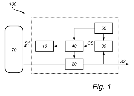
Fig. 1 is a schematic view of a system according to an embodiment.
Fig. 2 is a schematic view of a method of bioimpedance signal
acquisition.
Fig. 3 is a schematic view of a method of calibration of a system.
Fig. 4 is a schematic view of a method of bioimpedance signal
acquisition taking respiratory events into account.
Fig. 5 is a schematic view of a method of adapting bioimpedance
signal acquisition according to a first embodiment.
Fig. 6 is a schematic view of a method of adapting bioimpedance
signal acquisition according to a second embodiment.
Fig. 7 is a schematic view of a method of adapting bioimpedance
signal acquisition based on detection of posture of a subject.
Fig. 8 is a schematic view of a method of adapting bioimpedance
signal acquisition based on selecting electrodes to be used.
Detailed description
Fig. 1 illustrates an electronic system 100 for bioimpedance signal
acquisition.
The system 100 is configured to generate a current signal Si that is to be
applied to a subject and to measure a bioimpedance signal S2 providing
information of the bioimpedance of the subject, which may be further
processed, e.g. for monitoring respiration of the subject. The system 100 is
configured to adaptively change settings in order to maintain desired data
quality of the measured bioimpedance signal S2.
As shown in Fig. 1, the system 100 comprises a current signal injection
module 10. The current signal injection module 10 may be configured to
generate and output the current signal Si, which is to be applied to the
subject. The current signal injection module 10 may comprise a current
source for generating a current signal Si. The current signal injection module
10 may further comprise settings, which may be used for controlling the
current signal Si being generated and output by the current injection module
10.
The current signal injection module 10 may be configured to output an
AC current signal. The settings of the current signal injection module 10 may
control an amplitude and a frequency of the generated current signal Si.
CA 03083151 2020-05-21
WO 2019/115226 PCT/EP2018/082826
17
The system 100 further comprises a bioimpedance signal
measurement module 20. The bioimpedance signal measurement module 20
may be configured to receive voltage input signals representing a voltage
generated by the current signal Si applied to the subject. The bioimpedance
signal measurement module 20 may be configured to extract a measured
bioimpedance signal S2 from the received voltage input signals.
The bioimpedance signal measurement module 20 may comprise
settings, which may be used for controlling the extraction of the bioimpedance
signal S2 from the received voltage input signals. For instance, a gain of the
measured bioimpedance signal S2 may be controlled by the settings.
The bioimpedance signal measurement module 20 may be configured
to process the received voltage input signals, e.g. by filtering the input
signals, in order to extract relevant information. The filtering of the input
signals may also be controlled by settings of the bioimpedance signal
measurement module 20 or may be performed according to a fixed set-up.
The bioimpedance signal measurement module 20 may output the
measured bioimpedance signal S2, which may be used for determining a
condition of the subject by further processing of the measured bioimpedance
signal S2. For instance, the measured bioimpedance signal S2 may be used
for monitoring respiration of the subject. The further processing of the
measured bioimpedance signal S2 may be performed by an analysis module
within the system 100. However, according to an alternative, the measured
bioimpedance signal S2 is output to an external unit for further processing.
The system 100 further comprises a data quality detection module 30,
which is configured to receive the measured bioimpedance signal S2. The
data quality detection module 30 may be configured to detect and AC level
and/or a DC level of the measured bioimpedance signal S2.
The data quality detection module 30 may further store an AC
reference value range and/or a DC reference value range. The AC reference
value range and/or the DC reference value range may be set to define
acceptable AC levels and DC levels, respectively, for high quality data
acquisition. Alternatively, the AC reference value range and/or the DC
reference value range may be set to define non-acceptable AC levels and DC
levels, respectively, for high quality acquisition.
The data quality detection module 30 may be configured to detect
whether the AC level and/or the DC level of the measured bioimpedance
signal S2 is within or outside the AC reference value range and the DC
CA 03083151 2020-05-21
WO 2019/115226
PCT/EP2018/082826
18
reference value range, respectively. For instance, the data quality detection
module 30 may compare the detected AC level and/or the detected DC level
to the AC reference value range and the DC reference value range,
respectively.
In this way, the data quality detection module 30 may be configured to
determine whether data quality is not within acceptable limits, based on the
relation of the AC level and/or the DC level to the AC reference value range
and the DC reference value range, respectively.
When the data quality detection module 30 detects that the measured
bioimpedance signal S2 is of a non-acceptable data quality, a control signal
CS may be output by the data quality detection module 30.
The system 100 further comprises a signal adaptation module 40,
which is configured for modifying at least one parameter of the current signal
injection module 10 and/or the bioimpedance signal measurement module 20.
The signal adaptation module 40 may thus be configured to cause a change
settings of the system 100 so as to adaptively change the system 100. The
changing of the settings may ensure that a high quality bioimpedance signal
S2 is acquired even if conditions in which the bioimpedance signal S2 is
acquired are changed.
The signal adaptation module 40 may be configured for modifying at
least one parameter of the current signal injection module 10 and/or the
bioimpedance signal measurement module 20 based on whether the AC level
and/or the DC level of the measured bioimpedance signal S2 is within or
outside the AC reference value range and the DC reference value range,
respectively. This implies that the AC level and/or the DC level of the
measured bioimpedance signal S2 may be used as quality measure(s) of the
bioimpedance signal acquisition and the signal adaptation module 40 may be
configured to perform parameter modification based on the quality
measure(s).
The signal adaptation module 40 may be configured to send parameter
modification signals to the current signal injection module 10 and/or the
bioimpedance signal measurement module 20. The parameter modification
signal may comprise information that a parameter is to be modified and may
comprise a new value of the parameter. Alternatively, the parameter
modification signal may indicate whether a value of the parameter is to be
increased or decreased.
CA 03083151 2020-05-21
WO 2019/115226
PCT/EP2018/082826
19
The signal adaptation module 40 may be configured to modify at least
one of an amplitude of the generated current signal Si, a frequency of the
generated current signal Si, and a gain of the measured bioimpedance signal
S2.
The system 100 may further comprise electrodes 70, which may be
integrated with the system 100 and may be connected to the current signal
injection module 10 and the bioimpedance signal measurement module 20.
Alternatively, the electrodes 70 may be configured to be connected to the
system 100.
The electrodes 70 may be configured to be attached to the subject for
applying the current signal Si to the subject and for detecting a voltage
generated by the current Si passing through tissue of the subject. Two or
more electrodes 70 may be used and the electrodes 70 may be configured for
injecting the current signal Si and detecting a voltage by the same or by
different electrodes 70. Having more than two electrodes 70 may also allow
selectively choosing which electrodes 70 that should be part of the pair(s)
used for injecting the current signal Si and detecting the voltage generated
by the current signal Si.
The signal adaptation module 40 may further be configured to select
which electrodes 70 that are to be included in the electrode pair for
measuring
the bioimpedance signal. The signal adaptation module 40 may in this regard
send a parameter modification signal to the bioimpedance signal
measurement module 20 for controlling which input signals that are to be
selected by the bioimpedance signal measurement module 20.
During a process of parameter modification, the signal adaptation
module 40 may send parameter modification signals to the current signal
injection module 10 and/or the bioimpedance signal measurement module 20.
Then, a quality of the measured bioimpedance signal S2 based on changed
parameters, may be detected in the data quality detection module 30. As long
as the quality is not acceptable, the at least one parameter may be
continuously modified by further parameter modification signals from the
signal adaptation module 40. When an acceptable data quality is detected by
the data quality detection module 30, a new control signal CS may be sent to
the signal adaptation module 40 terminating the process of parameter
modification.
The AC reference value range and the DC reference value range may
also be changed in association with parameter modification. For instance, if
CA 03083151 2020-05-21
WO 2019/115226
PCT/EP2018/082826
the parameter modification process results in that a best possible signal
quality is not within desired ranges, the AC reference value range and the DC
reference value range may be changed such that the data quality detection
module will not constantly trigger a parameter modification. This may allow
5 acquiring bioimpedance signal of a relatively high quality. When it is
detected
that a higher quality signal may again be acquired, the AC reference value
range and the DC reference value range may again be changed for
controlling the system to acquire signal quality within desired ranges.
The data quality detection module 30 may be configured to
10 continuously detect quality of the measured bioimpedance signal S2.
Thus,
as soon as signal quality deteriorates, this may be detected in the data
quality
detection module 30.
Alternatively, the data quality detection module 30 may be configured
to detect quality at predetermined intervals. This may be regular intervals or
15 .. intervals depending on input that may indicate a likelihood of data
quality
deteriorating. By the data quality detection module 30 detecting quality at
intervals, data processing power may be saved, while allowing detection of
unacceptable data quality fairly quickly. For instance, the data quality
detection module 30 may detect quality every 10 seconds.
20 Adaptation of the system 100 for bioimpedance signal acquisition may
be needed when the subject changes posture. The posture change may for
instance affect a relation between electrodes 70 and/or between electrodes
70 and the subject. Thus, a posture change may often be associated with a
need of adapting the system 100.
The system 100 may further comprise a posture detection module 50.
The posture detection module 50 may be configured to receive information
relevant to a subject's posture from a sensor, such as an accelerometer
mounted on the subject and/or a camera monitoring a scene in which the
subject is located. The posture detection module 50 may be configured to
.. process the information in order to determine a posture of the subject.
The posture detection module 50 need not necessarily determine an
absolute posture of the subject. According to an alternative, the posture
detection module 50 may be configured to determine that a posture change
occurs.
When the posture detection module 50 determines a changed posture
(or a change in posture), the posture detection module 50 may provide a
signal to the signal adaptation module 40 in order to trigger parameter
CA 03083151 2020-05-21
WO 2019/115226
PCT/EP2018/082826
21
modification. Alternatively or additionally, the posture detection module 50
may provide a signal to the data quality detection module 30 in order to
trigger checking of quality of the measured bioimpedance signal S2, which
may in turn trigger parameter modification.
The system 100 may be calibrated to adapt the system 100 to a
subject. Thus, the system 100 may be personalized and parameters
appropriate for acquiring bioimpedance signals of high quality for the subject
may be determined. The appropriate parameters may differ substantially
between different subjects, e.g. since bioimpedance may vary between
different subjects. Also, the appropriate parameters may differ depending on
placement of electrodes on the subject, so calibration may be needed before
each session of bioimpedance signal acquisition, even for the same subject.
Results of the calibration may be stored in a memory within the system
100. Thus, appropriate parameters may be retrieved from the memory. The
calibration may be performed based on different postures, such that when a
change to a specific posture is detected by the posture detection module 50,
appropriate parameters for the specific posture may be retrieved from the
memory. Thus, the system 100 may immediately be set to use appropriate
parameters, which should enable the system 100 to acquire the measured
bioimpedance signal S2 with a high quality for the changed posture. This may
imply setting the at least one of the amplitude of the current signal Si, the
frequency of the signal Si, the gain of the measured bioimpedance signal S2
and the electrodes to be included in the electrode pair for measuring the
bioimpedance signal. Also, setting the appropriate parameters may include
setting the AC reference value range and the DC reference value range to be
used by the data quality detection module 30.
As described in more detail below, the calibration need not beforehand
determine appropriate settings for different postures. The appropriate
settings
may alternatively be determined when a posture is first detected and, then,
the appropriate settings for the posture may be stored in order to enable re-
use.
The data quality detection module 30 may be configured to detect
whether the change to appropriate parameters does provide an output of a
high quality measured bioimpedance signal S2. If not, further parameter
modification may be triggered.
The system 100 may comprise a memory, which may store the
calibration data. The memory may be accessible for each of the current signal
CA 03083151 2020-05-21
WO 2019/115226 PCT/EP2018/082826
22
injection module 10, the bioimpedance signal measurement module 20, the
data quality detection module 30 in order to retrieve appropriate settings for
the modules. Alternatively or additionally, the memory may be accessible by
the signal adaptation module 40, which may then send information of the
appropriate settings to the other modules. The system 100 may comprise a
single memory which is accessible by the modules. Alternatively, each
module may comprise an internal memory which stores calibration data
relevant for that module.
Each of the modules 10, 20, 30, 40, 50 may be implemented in
hardware, or as any combination of software and hardware. At least part of
the modules 10, 20, 30, 40, 50 may, for instance, be implemented as software
being executed on a general-purpose computer. The system 100 may thus
comprise one or more processing units, such as a central processing unit
(CPU), which may execute the instructions of one or more computer
programs in order to implement functionality of the modules. Thus, the system
100 may comprise a single processing unit, which may provide functionality of
each of the modules 10, 20, 30, 40, 50, e.g. as separate threads within the
processing unit.
The modules 10, 20, 30, 40, 50 may alternatively be implemented as
firmware arranged e.g. in an embedded system, or as a specifically designed
processing unit, such as an Application-Specific Integrated Circuit (ASIC) or
a
Field-Programmable Gate Array (FPGA).
The current signal injection module 10 may comprise circuitry for
converting control instructions, which may be implemented in software and/or
hardware, to an actual current signal 51, which may be output to electrodes
70 for being applied to a subject.
The bioimpedance signal measurement signal 20 may comprise
circuitry for converting control instructions, which may be implemented in
software and/or hardware, to forming a bioimpedance signal based on
received input voltage signals.
The system 100 may comprise a housing, in which the modules 10, 20,
30, 40, 50 may be arranged. The system 100 may thus be delivered in a
single package and may comprise a simple interface for putting the system
100 into use.
The housing may for instance comprise ports, to which electrodes 70
may be connected for receiving the current signal 51 and providing voltage
CA 03083151 2020-05-21
WO 2019/115226
PCT/EP2018/082826
23
signals representing a bioimpedance. Alternatively, electrodes 70 may be pre-
attached to the housing on delivery of the system 100.
The housing may further comprise an output port for connection to an
external unit, which may receive the measured bioimpedance signal S2 for
further processing of the signal. Alternatively or additionally, the housing
may
comprise a communication unit for wireless communication of the
bioimpedance signal S2 to the external unit.
The housing may further comprise additional ports for connecting
further units to the system 100, such as one or more sensors for detecting
posture of the subject.
The housing may be configured to be worn by a subject, such that the
system 100 allowing acquisition of the measured bioimpedance signal S2 with
high quality may be worn and used for long-term monitoring of the subject.
The housing may comprise a strap for attaching the housing to or around a
body part of the subject or may have a shape so as to allow the housing to be
worn by the subject.
Referring now to Figs 2-8, use of the system 100 in bioimpedance
signal acquisition will be further described.
Fig. 2 illustrates a general overview of bioimpedance signal acquisition.
As shown in Fig. 2, two or more electrodes 70 may be attached to a subject.
A further electrode 72, which may provide a bias voltage may optionally be
used.
The system 100 measures 200 a bioimpedance signal using a set
amplitude and frequency of a current signal Si, set gain of the bioimpedance
signal measurement module 20 and set electrode pair as input to the
bioimpedance signal measurement module 20.
The measured bioimpedance signal S2 may be provided as a digital or
analog signal. The AC level and/or DC level may be monitored 202 by the
data quality detection module 30. If it is determined that the AC level and/or
DC level is within or outside the AC reference value range and the DC
reference value range, respectively, adaptation 204 of the parameters for
bioimpedance signal acquisition may be performed. Then, the system 200
may again measure 200 the bioimpedance signal using the new
parameter(s).
As also illustrated in Fig. 2, a sensor, e.g. an accelerometer, may
acquire 206 a signal representing posture of the subject. The acquired signal
may be monitored 208 in order to determine an absolute posture and/or
CA 03083151 2020-05-21
WO 2019/115226
PCT/EP2018/082826
24
determine a change in posture. If the posture monitoring reveals that a
posture has changed, a signal may be sent for triggering the monitoring 202
of the AC level and/or the DC level of the measured bioimpedance signal S2.
Optionally, if posture dependent settings have been stored, a signal
may also be sent for triggering adaptation 204 of the parameters for
bioimpedance signal acquisition (using stored parameter settings).
Referring now to Fig. 3, a calibration procedure will be described. The
calibration may be performed before each session of bioimpedance signal
acquisition. The calibration may determine appropriate settings for a subject
and for a placement of the electrodes 70 on the subject. Calibration data may
be stored by the system 100 for re-use between different sessions on a
subject, such that calibration need not necessarily be performed before each
session.
The calibration may be performed for several different postures, such
that calibration data applying to each posture may be stored. This may allow
retrieving appropriate settings based on detection of a specific posture.
According to an alternative, the calibration is only performed for one
posture in order to initialize bioimpedance measurements. This may allow
quickly starting bioimpedance measurements, but the system 100 may not as
quickly adapt to new postures.
According to an embodiment, illustrated in Fig. 3, the calibration may
start by providing settings of the frequency of the current signal Si and the
gain of the measured bioimpedance signal S2 to generate as large signal as
possible. An amplitude of the current signal Si is swept 300 over all possible
current amplitudes.
During sweeping of the amplitude of the current signal Si, the
measured bioimpedance signal S2 is acquired for each setting of the
amplitude. The AC level and/or DC level of the measured bioimpedance
signal S2 is monitored 302. The AC reference value range and/or the DC
reference value range may be provided 304 as input to the monitoring of the
AC and/or DC levels. The AC reference value range and/or the DC reference
value range may be set as fixed values in the system 100 or may be based
on subject characteristics, which may be manually input. The subject
characteristics may include body mass index (BMI) of the subject, gender of
the subject, and position of electrodes 70 on the subject.
The monitoring of the AC level and/or DC level may compare the AC
and/or DC levels to the AC reference value range and the DC reference value
CA 03083151 2020-05-21
WO 2019/115226
PCT/EP2018/082826
range, respectively, in order to determine whether the AC level and/or DC
level are within acceptable ranges as set by the AC reference value range
and/or the DC reference value range.
The AC reference value range may indicate whether respiration
5 information may be extracted from the measured bioimpedance signal. The
AC reference value range may according to an embodiment be set as
exceeding 90% of a reference value, ACref0. The reference value may be
based on a desired signal-to-noise ratio (SNR) and may be based on a fixed
pre-set value or a value dependent on subject characteristics as mentioned
10 above. The reference value may be related to a level of the detected
signal so
that, if the AC level is at least 90% of the reference value, the SNR will be
acceptable. However, it should be realized that the AC reference value may
be set to any value and then, the AC reference value range may be
correspondingly set based on a percentage of the AC reference value
15 depending on which AC reference value is chosen. Hence, the AC reference
value range may correspond to at least 80% of the reference value or 100%
of the reference value, instead.
In one embodiment, the AC reference value may initially be set to a
default value that is known to give good measurement results. Then, the AC
20 reference value may be updated to correspond to an AC level providing
highest signal quality during the calibration process which will be further
desribed below.
The DC reference value range may indicate whether saturation of the
signal occurs. Thus, the DC reference value range may in one embodiment
25 be defined as 5-95% of an operation range DCref0 of the system 100.
Thus, by
the DC level being within the DC reference value range, the measured
bioimpedance signal S2 will not be saturated and information may be
extracted from the signal.
The AC reference value range and the DC reference value range may
be defined in relation to a respective reference value. Thus, a single
reference value may be provided, such that, when monitoring the AC and/or
DC levels, the AC reference value range and the DC reference value range
may be formed based on input of a single value.
The AC level may be measured as a voltage difference between a
peak representing a maximum value and a following peak representing a
minimum value. The DC level may be measured as an average voltage
around which the AC level oscillates.
CA 03083151 2020-05-21
WO 2019/115226 PCT/EP2018/082826
26
If the criterion or criteria are met, the calibration may be terminated and
a setting of the amplitude of the current signal Si may be selected 306. The
settings of the frequency of the current signal Si and the gain of the
measured bioimpedance signal S2 generating best signal quality are also
selected.
If only the DC level is monitored, the current amplitude generating a
highest DC level signal without exceeding a saturation criterion set by the DC
reference value range may be selected.
If only the AC level is monitored, the current amplitude generating a
highest AC level may be selected.
If both the AC level and the DC level are monitored, the current
amplitude generating a DC level signal within the DC reference value range
and a highest AC level may be selected.
If the criterion or criteria are not met by any of the amplitude settings of
the injected current signal Si, a gain of the bioimpedance signal
measurement module 20 is changed to the next level and a new current
amplitude sweep is made. This is repeated 308 for different gain settings,
changing the gain in steps from a gain providing a highest signal level to a
gain providing a lowest signal level of the measured bioimpedance signal S2.
During the changing of gain level and current amplitude sweep, the AC and/or
DC levels are monitored, as explained above in step 304.
Again, if the criterion or criteria are met, the calibration may be
terminated and settings of the parameters may be selected 310. The settings
of the frequency of the current signal Si generating best signal quality may
then be selected together with a gain and a current amplitude based on the
sweep. If the criterion or criteria are met, the gain need not be changed to
check all possible gains, but rather the gain level for which the criterion or
criteria are met may be selected. Further, the current amplitude may be
selected based on highest AC or DC level as described above.
If the criterion or criteria are still not met by any of the combination of
amplitude settings of the injected current signal Si and the gain of the
bioimpedance signal measurement module 20, a frequency of the current
signal Si is changed to the next level. Then, a new sweep of the gain of the
bioimpedance signal measurement module 20 and the amplitude of the
injected current signal Si as made in 308 is repeated. This is repeated 312
for different frequency settings, changing the frequency in steps from a
frequency providing a highest signal level to a frequency providing a lowest
CA 03083151 2020-05-21
WO 2019/115226
PCT/EP2018/082826
27
signal level of the measured bioimpedance signal S2. During the changing of
the frequency level, the gain level and the current amplitude sweep, the AC
and/or DC levels are monitored, as explained above in 304.
Again, if the criterion or criteria are met, the calibration may be
terminated and settings of the parameters may be selected 314. The settings
of the amplitude and frequency of the current signal Si, and the gain may
then be selected based on highest AC or DC level as described above. All
levels of frequencies need not be swept, but rather the frequency level for
which the criterion or criteria are met may be selected.
It should also be realized that an order in which parameters are
changed during calibration need not necessarily be in the order described
above. Rather, parameters may be changed in any order for determining
appropriate settings.
In an embodiment, the amplitude of the current signal Si may be
varied between 10 pA and 1 mA using a step size of 10 pA. The gain of the
bioimpedance signal measurement module 20 may be varied between 50 VA/
and 500 VA/ using a step size of 10 VN. The frequency of the current signal
Si may be varied between 1 kHz and 1 MHz using a step size of 10 kHz. It
should be realized that other ranges and step sizes may be used.
Referring now to Fig. 4, data quality monitoring in relation to both the
AC and the DC level of the measured bioimpedance signal will be described.
Thus, the adaptive bioimpedance signal acquisition is in this embodiment
based on both AC and DC level of the signal. This adaptive bioimpedance
signal acquisition may be especially suitable for sleep monitoring or in any
other situation where respiratory events may be expected, as the adaptation
is configured to take into account that loss of data quality may be due to
respiratory events.
The AC and DC levels are monitored 400. The AC and DC levels may
be extracted from the measured bioimpedance signal S2 at regular time
intervals. For instance, the AC and DC levels may be extracted every 10
seconds, which allows quickly detecting a low data quality, without requiring
constantly determining the AC and DC levels.
The AC and DC levels may be extracted based on input of a posture
change from posture monitoring 402, if such is performed. The detection of a
posture change may indicate a likelihood that the bioimpedance signal
acquisition may need adaptation and, therefore, may trigger extra monitoring
of AC and DC levels.
CA 03083151 2020-05-21
WO 2019/115226
PCT/EP2018/082826
28
The AC and DC levels may be monitored and compared to AC
reference value range and DC reference value range as set during
calibration. It should be noted that at least the AC reference value range may
be set in dependence on the chosen settings during calibration.
If both the AC level and the DC level are within the AC reference value
range and the DC reference value range, i.e. indicate that the data quality is
acceptable, measurement of the bioimpedance may be ongoing 404 and no
signal adaptation is necessary.
If the DC level is out of range, the measured bioimpedance signal S2 is
saturated, which implies that information may not be extracted. Thus, if it is
detected that the DC level is out of range, adaptation 406, as will be
described later, may be initiated.
If the AC level is out of range, i.e. the AC signal level is low, this may
be due to a respiratory event, such as apnea, shallow breathing or hypopnea.
Thus, adaptation of the bioimpedance signal acquisition may not necessarily
be needed or should not even be performed, as adaptation should be
performed based on conditions of acquiring the bioimpedance signal
changing, not based on the bioimpedance information changing.
Hence, if it is detected that the AC level is out of range, but the DC
level is still within the range of the DC reference value range, data quality
may
be continuously monitored 408 for a period of time. For instance, the data
quality may be monitored for 60 seconds. Thus, data quality may be
monitored during such a long period of time that, if the AC level being out of
range was due to a respiratory event, normal respiration may be resumed.
The DC level may also be used in order to determine whether a
detection of the AC level being out of range relates to a change that needs
signal adaptation (such as due to a change in posture) or relates to a
respiratory event. If the AC level is detected to be out of range and it is
simultaneously detected that the DC level has changed, the change may
likely be due to a posture change and not due to a respiratory event. Then,
adaptation 406 may be initiated. However, if the DC level has not changed,
the detection of the AC level being out of range has a higher likelihood to be
due to a respiratory event and data quality may then be continuously
monitored 408 for a period of time.
If the AC level returns to being within the AC reference value range,
ongoing measurement 404 of the bioimpedance signal may be resumed and
no signal adaptation is necessary.
CA 03083151 2020-05-21
WO 2019/115226
PCT/EP2018/082826
29
If, on the other hand, the AC level does stay outside the AC reference
value range, it may be determined that the change in AC level was not due to
a respiratory event. Hence, adaptation 406, as will be described later, may be
initiated.
As an alternative or in addition to monitoring the AC level and the DC
level for a period of time, the system 100 may comprise additional sensor(s)
which may be configured to detect respiratory events. Such sensor(s) may
e.g. measure whether any chest movement occurs for detecting apnea. Also,
the bioimpedance measurement may be used for detecting respiratory
events. Thus, if a respiratory event is detected, the ongoing measurement
406 may continue and the monitoring 400 of the AC and DC levels may be
performed again at regular time intervals.
Referring now to Fig. 5, parameter modification according to a first
embodiment of adaptation of the bioimpedance signal acquisition will be
described. The parameter modification according to the first embodiment
resembles the calibration process as described above with reference to Fig.
3.
The adaptation according to the first embodiment aims to establish
settings that provide a high quality bioimpedance signal. The settings are
established without any prejudice to certain settings previously used.
Thus, similar to the calibration described with reference to Fig. 3, the
adaptation may start by providing settings of the frequency of the current
signal 51 and the gain of the measured bioimpedance signal S2 to generate
best signal quality. An amplitude of the current signal 51 is swept 500 over
all
possible current amplitudes.
During sweeping of the amplitude of the current signal 51, the
measured bioimpedance signal S2 is acquired for each setting of the
amplitude. The AC level and/or DC level of the measured bioimpedance
signal S2 is monitored 502. The AC reference value range and/or the DC
reference value range may be provided 504 as input to the monitoring of the
AC and/or DC levels, or a single value may be provided as input allowing
forming of the AC reference value range and the DC reference value range.
At least the AC reference value range may be based on an adapted AC
reference value AC ref which may be set during use of the system 100 and
does not necessarily correspond to the AC reference value ACref0 as used
during calibration. The DC reference value range may be based on the same
DC reference value DCref0 as used during calibration.
CA 03083151 2020-05-21
WO 2019/115226
PCT/EP2018/082826
The monitoring of the AC level and/or DC level may compare the AC
and/or DC levels to the AC reference value range and the DC reference value
range, respectively, in order to determine whether the AC level and/or DC
level are within acceptable ranges as set by the AC reference value range
5 and/or the DC reference value range.
As explained for calibration above, if the criterion or criteria are met,
the adaptation may be terminated and a setting of the amplitude of the current
signal Si may be selected 506. The settings of the frequency of the current
signal Si and the gain of the measured bioimpedance signal S2 generating
10 best signal quality are also selected.
Further, as explained for calibration above, if the criterion or criteria are
not met by any of the amplitude settings of the injected current signal Si,
the
gain of the bioimpedance signal measurement module 20 is changed 508 and
current amplitude sweeps are made for different gain settings, while
15 monitoring the AC and/or DC levels.
Again, if the criterion or criteria are met, the calibration may be
terminated and settings of the parameters may be selected 510 based on
highest AC or DC level of the signal.
If the criterion or criteria are still not met by any of the combination of
20 amplitude settings of the injected current signal Si and the gain of the
bioimpedance signal measurement module 20, a frequency of the current
signal Si is changed to the next level. Then, a new sweep of the gain of the
bioimpedance signal measurement module 20 and the amplitude of the
injected current signal Si as made in 508 is repeated. This is repeated 512
25 for different frequency settings, while the AC and/or DC levels are
monitored.
Again, if the criterion or criteria are met, the adaptation may be
terminated and settings of the parameters may be selected 514. The settings
of the amplitude and frequency of the current signal Si, and the gain may
then be selected based on highest AC level of the signal.
30 If the criteria are still not met, it may be determined that the
criteria may
not be met and the settings providing best results may be used. Thus, the
adaptation may end with the setting of the amplitude, the gain and the
frequency being updated with values for which best results are obtained.
Referring now to Fig. 6, parameter modification according to a second
embodiment of adaptation of the bioimpedance signal acquisition will be
described. The parameter modification according to the second embodiment
makes use of previous settings and tries to change the settings based on the
CA 03083151 2020-05-21
WO 2019/115226
PCT/EP2018/082826
31
previous settings in order to quickly arrive at an adapted bioimpedance signal
acquisition which provides high quality data.
The adaptation receives 602 the AC reference value range and/or the
DC reference value range as input to the monitoring of the AC and/or DC
levels, or a single value may be received as input allowing forming of the AC
reference value range and the DC reference value range. At least the AC
reference value range may be based on an adapted AC reference value
ACref, which may be set during use of the system 100 and does not
necessarily correspond to the AC reference value ACref0 as used during
calibration. The DC reference value range may be based on the same DC
reference value DCref0 as used during calibration.
The adaptation is started 604 monitoring the AC level and/or the DC
level against the AC reference value range ACref and the DC reference value
range DCref0. Also, the current parameter values of the at least one parameter
.. of the current signal injection module 10 and the bioimpedance signal
measurement module 20 are used as initial values.
If it is found that the AC level is outside the AC reference value range,
e.g. <0.9*ACref, it may be determined that an increase in the amplitude of the
measured bioimpedance signal S2 is needed. Thus, the adaptation may use
the present settings of parameter values and adapt the bioimpedance signal
acquisition in relation to the present settings.
First, values of the gain of the bioimpedance signal measurement
module 20 and the frequency of the current signal Si according to the
present settings may be maintained. The amplitude of the current signal Si
may be increased 606 in sequential steps. During increasing of the amplitude
of the current signal Si, the measured bioimpedance signal S2 is acquired for
each setting of the amplitude. The AC level and the DC level of the measured
bioimpedance signal S2 is monitored and compared to the AC reference
value range and the DC reference value range, respectively. Thus, it is
determined whether the criteria are met and the increasing of the amplitude of
the current signal Si is continued until the criteria are met or a maximum
amplitude is reached.
If the criteria are met, the adaptation may be terminated and the setting
of the amplitude is updated 608 with a value for which the criteria are met.
Also, the AC reference value ACref is updated based on the new setting of the
amplitude of the current signal Si.
CA 03083151 2020-05-21
WO 2019/115226
PCT/EP2018/082826
32
If the criteria are not met by any of the amplitude settings of the
injected current signal Si, the gain of the bioimpedance signal measurement
module 20 is increased to the next level and a current amplitude sweep is
made. This is repeated 610 for different gain settings, changing the gain in
steps towards a maximum gain. During the increasing of the gain level and
the current amplitude sweep, the AC and DC levels are monitored.
If the criteria are met, the adaptation may be terminated and the setting
of the amplitude and the gain are updated 612 with values for which the
criteria are met. Also, the AC reference value ACref is updated based on the
new setting of the amplitude of the current signal Si.
If the criteria are not met by any of the combinations of amplitude and
gain settings, the frequency of the current signal Si is changed. Depending
on a position on the semi-circular relation in the Cole-Cole plot of the
resistance and reactance parts of the measured bioimpedance signal S2, the
frequency may be decreased or increased to the next level and a sweep of
current amplitude and gain settings is made. This is repeated 614 for
different
frequency settings, changing the frequency in steps towards a minimum or
maximum frequency. During the decreasing or increasing of the frequency
level and the gain and current amplitude sweep, the AC and DC levels are
monitored.
If the criteria are met, the adaptation may be terminated and the setting
of the amplitude, the gain and the frequency are updated 616 with values for
which the criteria are met. Also, the AC reference value ACref is updated
based on the new setting of the amplitude of the current signal Si.
If the criteria are not met for any frequency, it may be determined that
the criteria may not be met and the settings providing best results may be
used. Thus, the adaptation may end with the setting of the amplitude, the gain
and the frequency being updated 618 with values for which best results are
obtained. Also, the AC reference value ACref is updated based on the new
setting of the amplitude of the current signal Si.
The process of adapting bioimpedance signal acquisition for increasing
the AC level may also be performed in relation to a maximum time. Thus, a
maximum time may be set, such that parameter modification may not
continue for a time period exceeding the maximum time. This implies that a
time period during which bioimpedance signal data may not be analyzed is
limited, as the bioimpedance signal during parameter modification may not be
CA 03083151 2020-05-21
WO 2019/115226
PCT/EP2018/082826
33
used as providing reliable data (e.g. because the conditions during which the
bioimpedance signal is measured is constantly changed).
Thus, if the adaptation process has not terminated within the maximum
time, the settings providing best results may be used. Thus, the adaptation
may end when reaching the maximum time with the setting of the amplitude,
the gain and the frequency being updated with values for which best results
are obtained. Also, the AC reference value AC ref is updated based on the new
setting of the amplitude of the current signal Si.
According to an embodiment, the maximum time may be set to at least
30 seconds, which may give reasonable time for allowing adaptation to be
performed.
If it is found when the adaptation is started at 604 that the DC level is
outside the DC reference value range, e.g. that DC saturation occurs or is
close to occurring due to the DC level >0.95*DCrefo, it may be determined that
a decrease in the amplitude of the measured bioimpedance signal S2 is
needed. Thus, the adaptation may use the present settings of parameter
values and adapt the bioimpedance signal acquisition in relation to the
present settings.
First, values of the gain of the bioimpedance signal measurement
module 20 and the frequency of the current signal Si according to the
present settings may be maintained. The amplitude of the current signal Si
may be decreased 620 in sequential steps. During decreasing of the
amplitude of the current signal Si, the measured bioimpedance signal S2 is
acquired for each setting of the amplitude. The AC level and the DC level of
the measured bioimpedance signal S2 is monitored and compared to the AC
reference value range and the DC reference value range, respectively. Thus,
it is determined whether the criteria are met and the increasing of the
amplitude of the current signal Si is continued until the criteria are met or
a
minimum amplitude is reached.
If the criteria are met, the adaptation may be terminated and the setting
of the amplitude is updated 622 with a value for which the criteria are met.
Also, the AC reference value ACref is updated based on the new setting of the
amplitude of the current signal Si.
If the criteria are not met by any of the amplitude settings of the
injected current signal Si, the gain of the bioimpedance signal measurement
module 20 is decreased to the next level and a current amplitude sweep is
made. This is repeated 624 for different gain settings, changing the gain in
CA 03083151 2020-05-21
WO 2019/115226
PCT/EP2018/082826
34
steps towards a minimum gain. During the decreasing of the gain level and
the current amplitude sweep, the AC and DC levels are monitored.
If the criteria are met, the adaptation may be terminated and the setting
of the amplitude and the gain are updated 626 with values for which the
criteria are met. Also, the AC reference value ACref is updated based on the
new setting of the amplitude of the current signal Si.
If the criteria are not met by any of the combinations of amplitude and
gain settings, the frequency of the current signal Si is changed. Depending
on a position on the semi-circular relation in the Cole-Cole plot of the
resistance and reactance parts of the measured bioimpedance signal S2 and
the frequency of the current signal Si, the frequency may be increased or
decreased to the next level and a sweep of current amplitude and gain
settings is made. This is repeated 628 for different frequency settings,
changing the frequency in steps towards a maximum or minimum frequency.
During the increasing or decreasing of the frequency level and the gain and
current amplitude sweep, the AC and DC levels are monitored.
If the criteria are met, the adaptation may be terminated and the setting
of the amplitude, the gain and the frequency are updated 630 with values for
which the criteria are met. Also, the AC reference value ACref is updated
based on the new setting of the amplitude of the current signal Si.
If the criteria are not met for any frequency, it may be determined that
the criteria may not be met and the settings providing best results may be
used. Thus, the adaptation may end with the setting of the amplitude, the gain
and the frequency being updated 632 with values for which best results are
obtained. Also, the AC reference value ACref is updated based on the new
setting of the amplitude of the current signal Si. However, if the DC level is
still saturated or close to saturating, it may not be possible to extract
meaningful information from the measured bioimpedance signal S2 and a
new adaptation may be immediately triggered.
The adaptation of the bioimpedance signal acquisition according to the
first embodiment discussed with reference to Fig. 5, may be useful in
adapting the system 100 when a posture change has occurred. A posture
change may significantly change conditions in which the bioimpedance signal
is acquired and using the present settings as starting point for adaptation
may
not be relevant. The adaptation of the bioimpedance signal acquisition
according to the second embodiment discussed with reference to Fig. 6, may
be useful in adapting the system 100 when the signal drifts out of an
CA 03083151 2020-05-21
WO 2019/115226 PCT/EP2018/082826
acceptable range. Then, only a small change in parameter values may be
needed and the adaptation according to the second embodiment may very
quickly terminate with updated settings.
Thus, a system 100 may make use of both embodiments and may
5 choose which adaptation process to be used based on further input. Such
further input may be input indicating that a posture change has occurred or
determining that a sudden large change in the AC and/or DC level has
occurred.
However, it should be realized that the determining which of the first
10 and second embodiments of adaptation of the bioimpedance signal
acquisition should be used may be based on other conditions. Also, the
system 100 may be set up to use only one of the embodiments.
Referring now to Fig. 7, an embodiment of adaptation of the
bioimpedance signal acquisition in relation to a posture change will be
15 described.
The adaptation is based on input of a posture of the subject. Thus, as
described above, the posture detection module 50 is used for determining the
posture of the subject.
When a new posture is detected 702 by the posture detection module,
20 the adaptation may be started. First, the posture may be determined. Here,
the posture is denoted I.
Then, it is determined whether a previous measurement of the
bioimpedance signal has been done for the posture i, either during calibration
or during previous measurements. If no previous measurements have been
25 done, no calibration data for the posture i may be stored. Thus, an
adaptation
is made 704 either according to the first embodiment as discussed in relation
to Fig. 5 or according to the second embodiment as discussed in relation to
Fig. 6.
When the adaptation is finished, the bioimpedance signal acquisition
30 may be continued 706 using the determined settings. Further, the settings
of
the amplitude and frequency of the current signal and the gain of the
bioimpedance signal measurement module 20 may be stored in relation to the
posture i. Thus, the settings may be later retrieved, if the subject again
assumes the same posture i.
35 If it is found when a new posture i is detected 702 that previous
measurements have been done for the posture i, stored data applying to the
posture i may be retrieved. Then, the current amplitude and frequency and
CA 03083151 2020-05-21
WO 2019/115226
PCT/EP2018/082826
36
the gain may be set 708 using the retrieved values. The stored data may be
calibration data generated during calibration of the system 100. However,
when measurements are made in a posture i, the calibration data may be
updated with the last settings used with the subject being in the posture.
Once the retrieved settings have been set, the AC and/or DC levels
may be monitored in order to determine whether data quality is acceptable. In
this respect, the AC level may be compared to an AC reference value range
based on an AC reference value for the posture settings for the posture i,
AC ref,i .
If the criteria are met, the bioimpedance signal is acquired with
acceptable data quality and measurement of the bioimpedance signal may
continue 710 using the settings for the parameters.
If the criteria are not met, an adaptation is made 712 either according
to the first embodiment as discussed in relation to Fig. 5 or according to the
second embodiment as discussed in relation to Fig. 6.
When the adaptation is finished, the bioimpedance signal acquisition
may be continued 714 using the determined settings. Further, the settings of
the amplitude and frequency of the current signal and the gain of the
bioimpedance signal measurement module 20 may be stored in relation to the
posture i. Thus, the updated settings may be later retrieved, if the subject
again assumes the same posture i.
In the above, adaptation of the bioimpedance signal acquisition has
mainly been discussed using the amplitude of the current signal Si, the
frequency of the current signal Si and the gain of the measured
bioimpedance signal S2. However, adaptation of the bioimpedance signal
acquisition may alternatively or additionally use selection of which
electrodes
70 to be included for measuring the bioimpedance signal.
According to one embodiment, selection of electrodes 70 may be
performed during set-up of the system 100. Thus, the electrodes 70 to be
used may be selected based on subject characteristics, such as gender and
BM I, and on a position of the electrodes 70 on the subject (such as
positioning or orientation on chest). Hence, the electrodes 70 to be used may
be pre-selected and the same electrode pair(s) may be used throughout a
session of bioimpedance signal acquisition.
According to a second embodiment, selection of electrodes 70 may be
based on a calibration performed during set-up of the system 100. Thus, the
electrode pair(s) may be selected based on measurements of which
CA 03083151 2020-05-21
WO 2019/115226 PCT/EP2018/082826
37
electrodes 70 that provide a highest AC level of the measured bioimpedance
signal S2. Then, the selected electrodes 70 may be used throughout a
session of bioimpedance signal acquisition.
According to a third embodiment, selection of electrodes 70 may be
included both in a calibration process and in an adaptation process. Thus, the
selection of electrodes 70 may be included as a last step after the parameter
values of amplitude and frequency of the current signal Si and gain of the
measured bioimpedance signal S2 have been varied. Thus, if the criteria are
not met, the selection of electrodes 70 may be varied for different
configurations of electrodes 70 and the settings of the amplitude, gain and
frequency may be swept in order to find appropriate settings.
Referring to Fig. 8, selection of electrodes 70, which may be used in
the second or third embodiment, is discussed in further detail.
The electrode configuration is swept 800. If a two-electrode
measurement is used, i.e. the same electrodes 70 are used both for injecting
the current signal Si and sensing the voltage generated by the current signal
Si, the pair of electrodes 70 to be used may be varied starting with the
electrodes 70 being farthest away from each other towards the electrodes 70
being closest to each other.
For each electrode pair, the amplitude of the current signal Si, the gain
of the measured bioimpedance signal S2 and the frequency of the current
signal Si may be swept. During sweeping of the amplitude of the current
signal Si, the measured bioimpedance signal S2 is acquired for each setting.
The AC level and/or DC level of the measured bioimpedance signal S2 is
monitored 802. The AC reference value range and/or the DC reference value
range may be provided 804 as input to the monitoring of the AC and/or DC
levels, or single values ACref0 and DCref0 may be provided as input allowing
forming of the AC reference value range and the DC reference value range.
If the criterion or criteria are met, the adaptation may be terminated
and settings of the parameters including the electrodes 70 to be included in
the electrode pair may be selected 806 based on highest AC level of the
signal. If the criterion or criteria are met, all possible electrode pairs
need not
be checked, but rather the electrodes 70 for which the criterion or criteria
are
met may be selected.
The process of selecting electrodes 70 may also be performed in
relation to a maximum time. Thus, a maximum time may be set, such that
parameter modification may not continue for a time period exceeding the
CA 03083151 2020-05-21
WO 2019/115226
PCT/EP2018/082826
38
maximum time. Thus, if the adaptation process has not terminated within the
maximum time, the settings providing best results may be used.
If a four-electrode measurement is used, i.e. two electrodes 70 are
used for injecting the current signal Si and two other electrodes 70 are used
for sensing the voltage generated by the current signal Si, the electrode
sweep may start with two outer electrodes 70 having the largest distance
between them for applying the current signal Si to the subject in combination
with two inner electrodes 70, arranged between the two outer electrodes 70
and having the largest distance between them for sensing the generated
voltage.
For instance, if a row of six electrodes 70 are provided and the
electrodes are numbered 1-6 along the row, the electrode sweep may start by
using electrodes 1 and 6 for current signal injection and electrodes 2 and 5
for
voltage sensing. Then, a combination of electrodes 1 and 6 for current signal
injection and electrodes 3 and 4 for voltage sensing may be tested. Finally, a
combination of electrodes 2 and 5 for current signal injection and electrodes
3
and 4 for voltage sensing may be tested. If none of these set-ups provide a
bioimpedance signal of acceptable quality, a combination of electrodes 1 and
4 for current signal injection and electrodes 2 and 3 for voltage sensing may
__ be tested followed by a combination of electrodes 3 and 6 for current
signal
injection and electrodes 4 and 5 for voltage sensing.
In the above the inventive concept has mainly been described with
reference to a limited number of examples. However, as is readily
appreciated by a person skilled in the art, other examples than the ones
__ disclosed above are equally possible within the scope of the inventive
concept, as defined by the appended claims.
For instance, although it is described that parameters are modified in a
certain order during parameter modification in order to find settings allowing
bioimpedance signal acquisition to be made with high quality, it should be
realized that another order may be used and/or fewer or more parameters
may be used.