Note: Descriptions are shown in the official language in which they were submitted.
CA 03083194 2020-05-20
WO 2019/104237
PCT/US2018/062339
SYSTEMS AND METHODS FOR PRIMING FLUID CIRCUITS OF A PLASMA
PROCESSING SYSTEM
CROSS-REFERENCE
The present application relies on United States Provisional Patent Application
Number
62/589,919, entitled "Systems and Methods for Causing Regression of Arterial
Plaque" and filed
on November 22, 2017, for priority.
FIELD
The present invention generally relates to systems, apparatus and methods for
removing
lipids from HDL particles while leaving LDL particles substantially intact,
via the extracorporeal
treatment of blood plasma using either a single solvent or multiple solvents,
in order to regress
vulnerable arterial plaques, which is implicated in many disease states. More
specifically, the
presently disclosed inventions address the priming of the plasma processing
system and the
management of waste, particularly solvent waste, generated by the described
treatment processes.
BACKGROUND
Familial Hypercholesterolemia (FH) is an inherited genetic autosomal dominant
disease
characterized by markedly elevated low density lipoprotein (LDL), tendon
xanthomas, and
premature coronary heart disease, caused by mutations of "FH genes," which
include the LDL-
receptor (LDLR), apolipoprotein B-100 (APOB) or proprotein convertase
subtilisin/kexin type 9
(PC SK9).
FH produces a clinically recognizable pattern that consists of severe
hypercholesterolemia due to the accumulation of LDL in the plasma, cholesterol
deposition in
tendons and skin, as well as a high risk of atherosclerosis manifesting almost
exclusively as
coronary artery disease (CAD). In FH patients, this genetic mutation makes the
liver unable to
effectively metabolize (or remove) excess plasma LDL, resulting in increased
LDL levels.
If an individual has inherited a defective FH gene from one parent, the form
of FH is
called Heterozygous FH. Heterozygous FH is a common genetic disorder,
inherited in an
autosomal dominant pattern, occurring in approximately 1:500 people in most
countries. If the
individual has inherited a defective FH gene from both parents, the form of FH
is called
Homozygous FH. Homozygous FH is very rare, occurring in about 1 in 160,000 to
one million
1
CA 03083194 2020-05-20
WO 2019/104237
PCT/US2018/062339
people worldwide, and results in LDL levels >700 mg/di, 10 fold higher than
the ideal 70 mg/di
level desired for patients with CVD. Due to the high LDL levels, patients with
Homozygous FH
have aggressive atherosclerosis (narrowing and blocking of blood vessels) and
early heart attacks.
This process starts before birth and progresses rapidly. It can affect the
coronary arteries, carotid
arteries, aorta, and aortic valve.
Heterozygous FH (HeFH) is normally treated with statins, bile acid
sequestrants, or other
lipid lowering agents that lower cholesterol levels, and/or by offering
genetic counseling.
Homozygous FH (HoFH) often does not respond adequately to medical therapy and
may require
other treatments, including LDL apheresis (removal of LDL in a method similar
to dialysis), ileal
bypass surgery to dramatically lower their LDL levels, and occasionally liver
transplantation. A
few medications have recently been approved for use by HoFH subjects. However,
these
medications lower LDL only, and modestly contribute to slowing, but not
stopping, further
progression of atherosclerosis. Additionally, these medications are known to
have significant
side-effects.
Cholesterol is synthesized by the liver or obtained from dietary sources. LDL
is
responsible for transferring cholesterol from the liver to tissues at
different sites in the body.
However, if LDL collects on the arterial walls, it undergoes oxidation caused
by oxygen free
radicals liberated from the body's chemical processes and interacts
deleteriously with the blood
vessels. The modified LDL causes white blood cells in the immune system to
gather at the
arterial walls, forming a fatty substance called plaque and injuring cellular
layers that line blood
vessels. The modified oxidized LDL also reduces the level of nitric oxide,
which is responsible
for relaxing the blood vessels and thereby allowing the blood to flow freely.
As this process
continues, the arterial walls slowly constrict, resulting in hardening of the
arteries and thereby
reducing blood flow. The gradual build-up of plaque can result in blockage of
a coronary vessel
and ultimately in a heart attack. The plaque build up can also occur in
peripheral vessels such as
the legs and this condition is known as peripheral arterial disease.
Obstructions can also appear in blood vessels that supply blood to the brain,
which can
result in ischemic strokes. The underlying condition for this type of
obstruction is the
development of fatty deposits lining the vessel walls. It is known that at
least 2.7% of men and
women over the age of 18 in the United States have a history of stroke.
Prevalence of stroke is
also known to be higher with increasing age. With the increase in the aging
population, the
2
CA 03083194 2020-05-20
WO 2019/104237
PCT/US2018/062339
prevalence of stroke survivors is projected to increase, especially among
elderly women. A
considerable portion of all strokes (at least 87%) are ischemic in nature.
Further, it has been shown that hypercholesterolemia and inflammation are two
dominant
mechanisms implicated in the development of atherosclerosis. There is
significant overlap
between vascular risk factors for both Alzheimer's disease and
atherosclerosis. Inflammation
has been implicated in Alzheimer's disease pathogenesis and it is suggested
that abnormalities in
cholesterol homeostasis may have a role as well. In addition, many of the
contributory factors in
atherogenesis also contribute to Alzheimer's disease. Specifically, in cell
cultures, increased and
decreased cholesterol levels promote and inhibit the formation of beta amyloid
(A13) from
Amyloid Precursor Protein (APP), respectively. Thus, the use of treatments
with proven effects
on the process of atherosclerosis may be one method for treating the
progression of the
Alzheimer's disease.
Another common cardiovascular disease that occurs due to development of
atherosclerosis (hardening and narrowing of the arteries) within the elastic
lining inside a
coronary artery, is Coronary Artery Disease (CAD), also known as Ischemic
Heart Disease
(IHD). On the basis of a statistical data collected from 2009 to 2012, an
estimated 15.5 million
Americans > 20 years of age have CAD. The total CAD prevalence in the United
States is 6.2%
of adults > 20 years of age.
An acute decrease in blood flow in the coronary arteries may result in part of
the heart
muscle unable to function properly. This condition is known as Acute Coronary
Syndrome
(ACS). A conservative estimate for the number of hospital discharges with ACS
in 2010 is
625,000.
In contrast to LDL, high plasma HDL levels are desirable because they play a
major role
in "reverse cholesterol transport", where the excess cholesterol is
transferred from tissue sites to
the liver where it is eliminated. Optimal total cholesterol levels are 200
mg/di or below with a
LDL cholesterol level of 160 mg/di or below and a HDL-cholesterol level of 45
mg/di for men
and 50 mg/di for women. Lower LDL levels are recommended for individuals with
a history of
elevated cholesterol, atherosclerosis or coronary artery disease. High levels
of LDL increase the
lipid content in coronary arteries resulting in formation of lipid filled
plaques that are vulnerable
to rupture. On the other hand, HDL has been shown to decrease the lipid
content in the lipid
filled plaques, reducing the probability of rupture. In the last several
years, clinical trials of low
3
CA 03083194 2020-05-20
WO 2019/104237
PCT/US2018/062339
density lipoprotein (LDL)-lowering drugs have definitively established that
reductions in LDL
are associated with a 30-45% decrease in clinical cardiovascular disease (CVD)
events. CVD
events include events occurring in diseases such as HoFH, HeFH, and peripheral
arterial disease.
Despite lowered LDL, however, many patients continue to have cardiac events.
Low levels of
HDL are often present in high risk subjects with CVD, and epidemiological
studies have
identified HDL as an independent risk factor that modulates CVD risk. In
addition to
epidemiologic studies, other evidence suggests that raising HDL would reduce
the risk of CVD.
There has been increasing interest in changing plasma HDL levels by dietary,
pharmacological
or genetic manipulations as a potential strategy for the treatment of CVD
including HoFH, HeFH,
Ischemic stroke, CAD, ACS, and peripheral arterial disease and for treating
the progression of
Alzheimer's Disease.
The protein component of LDL, known as apolipoprotein-B (ApoB), and its
products,
comprise atherogenic elements. Elevated plasma LDL levels and reduced HDL
levels are
recognized as primary causes of coronary disease. ApoB is in highest
concentration in LDL
particles and is not present in HDL particles. Apolipoprotein A-I (ApoA-I) and
apolipoprotein
A-II (ApoA-II) are found in HDL. Other apolipoproteins, such as ApoC and its
subtypes (C-I,
C-II and C-III), ApoD, and ApoE are also found in HDL. ApoC and ApoE are also
observed in
LDL particles.
Numerous major classes of HDL particles including HDL2b, HDL2a, HDL3a, HDL3b
and HDL3 have been reported. Various forms of HDL particles have been
described on the basis
of electrophoretic mobility on agarose as two major populations, a major
fraction with a-HDL
mobility and a minor fraction with migration similar to VLDL. This latter
fraction has been
called pre-f3 HDL and these particles are the most efficient HDL particle
subclass for inducing
cellular cholesterol efflux.
The HDL lipoprotein particles are comprised of ApoA-I, phospholipids and
cholesterol.
The pre-f3 HDL particles are considered to be the first acceptors of cellular
free cholesterol and
are essential in eventually transferring free and esterified cholesterol to a-
HDL. Pre-f3 HDL
particles may transfer cholesterol to a-HDL or be converted to a-HDL. The
alpha HDL transfers
cholesterol to the liver, where excess cholesterol can be removed from the
body.
HDL levels are inversely correlated with atherosclerosis and coronary artery
disease.
Once cholesterol-carrying a-HDL reaches the liver, the a-HDL particles divest
of the cholesterol
4
CA 03083194 2020-05-20
WO 2019/104237
PCT/US2018/062339
and transfer the free cholesterol to the liver. The a-HDL particles (divested
of cholesterol) are
subsequently converted to pre-f3 HDL particles and exit the liver, which then
serve to pick up
additional cholesterol within the body and are converted back to a-HDL, thus
repeating the cycle.
Accordingly, what is needed is a method to decrease or remove cholesterol from
these various
HDL particles, especially the a-HDL particles, so that they are available to
remove additional
cholesterol from cells.
Hyperlipidemia (or abnormally high concentration of lipids in the blood) may
be treated
by changing a patient's diet. However, diet as a primary mode of therapy
requires a major effort
on the part of patients, physicians, nutritionists, dietitians, and other
health care professionals and
thus undesirably taxes the resources of health professionals. Another negative
aspect of this
therapy is that its success does not rest exclusively on diet. Rather, success
of dietary therapy
depends upon a combination of social, psychological, economic, and behavioral
factors. Thus,
therapy based only on correcting flaws within a patient's diet, is not always
successful.
In instances when dietary modification has been unsuccessful, drug therapy has
been
used as adjunctive therapy. Such therapy has included use of commercially
available
hypolipidemic drugs administered alone or in combination with other therapies
as a supplement
to dietary control. These drugs, called statins, include lovastatin,
pravastatin, simvastatin,
fluvastatin, atorvastatin, and cerivastatin. Statins are particularly
effective for lowering LDL
levels and are also effective in the reduction of triglycerides, apparently in
direct proportion to
their LDL-lowering effects. Statins raise HDL levels, but to a lesser extent
than other anti-
cholesterol drugs. Statins also increase nitric oxide, which, as described
above, is reduced in the
presence of oxidized LDL.
Bile acid resins, another drug therapy, work by binding with bile acid, a
substance made
by the liver using cholesterol as one of the primary manufacturing components.
Because the
drugs bind with bile acids in the digestive tract, they are then excreted with
the feces rather than
being absorbed into the body. The liver, as a result, must take more
cholesterol from the
circulation to continue constructing bile acids, resulting in an overall
decrease in LDL levels.
Nicotinic acid, or niacin, also known as vitamin B3, is effective in reducing
triglyceride
levels and raising HDL levels higher than any other anti-cholesterol drug.
Nicotinic acid also
lowers LDL-cholesterol.
5
CA 03083194 2020-05-20
WO 2019/104237
PCT/US2018/062339
Fibric acid derivatives, or fibrates, are used to lower triglyceride levels
and increase HDL
when other drugs ordinarily used for these purposes, such as niacin, are not
effective.
Probucol lowers LDL-cholesterol levels, however, it also lowers HDL levels. It
is
generally used for certain genetic disorders that cause high cholesterol
levels, or in cases where
other cholesterol-lowering drugs are ineffective or cannot be used.
PCSK9s lower LDL-cholesterol levels via increasing the cellular level of LDL
receptors
that reside in the liver.
Hypolipidemic drugs have had varying degrees of success in reducing blood
lipid;
however, none of the hypolipidemic drugs successfully treats all types of
hyperlipidemia. While
some hypolipidemic drugs have been fairly successful, the medical community
has found little
conclusive evidence that hypolipidemic drugs cause regression of
atherosclerosis. In addition,
all hypolipidemic drugs have undesirable side effects. As a result of the lack
of success of
dietary control, drug therapy and other therapies, atherosclerosis remains a
major cause of death
in many parts of the world.
New therapies have been used to reduce the amount of lipid in patients for
whom drug
and diet therapies were not sufficiently effective. For example,
extracorporeal procedures like
plasmapheresis and LDL-apheresis have been employed and are shown to be
effective in
lowering LDL.
Plasmapheresis therapy or plasma exchange therapy, involves replacing a
patient's
plasma with donor plasma or more usually a plasma protein fraction.
Plasmapheresis is a
process whereby the blood plasma is removed from blood cells by a cell
separator. The
separator works either by spinning the blood at high speed to separate the
cells from the fluid or
by passing the blood through a membrane with pores so small that only the
fluid component of
the blood can pass through. The cells are returned to the person undergoing
treatment, while the
plasma is discarded and replaced with other fluids.
This treatment has resulted in complications due to the introduction of
foreign proteins
and transmission of infectious diseases. Further, plasmapheresis has the
disadvantage of non-
selective removal of all serum lipoproteins, such as VLDL, LDL, and HDL.
Moreover,
plasmapheresis can result in several side effects including allergic reactions
in the form of fever,
chills, and rash and possibly even anaphylaxis.
6
CA 03083194 2020-05-20
WO 2019/104237
PCT/US2018/062339
As described above, it is not desirable to remove HDL, which is secreted from
both the
liver and the intestine as nascent, disk-shaped particles that contain
cholesterol and
phospholipids. HDL is believed to play a role in reverse cholesterol
transport, which is the
process by which excess cholesterol is removed from tissues and transported to
the liver for
reuse or disposal in the bile.
In contrast to plasmapheresis, the LDL-apheresis procedure selectively removes
ApoB
containing cholesterol, such as LDL, while retaining HDL. Several methods for
LDL-apheresis
have been developed. These techniques include absorption of LDL in heparin-
agarose beads, the
use of immobilized LDL-antibodies, cascade filtration absorption to immobilize
dextran sulfate,
and LDL precipitation at low pH in the presence of heparin. Each method
described above is
effective in removing LDL. This treatment process has disadvantages, however,
including the
failure to positively affect HDL or to cause a metabolic shift that can
enhance atherosclerosis and
other cardiovascular diseases. LDL apheresis, as its name suggests, merely
treats LDL in
patients with severe hyperlipidemia.
Yet another method of achieving a reduction in plasma cholesterol in
homozygous
familial hypercholesterolemia, heterozygous familial hypercholesterolemia and
patients with
acquired hyperlipidemia is an extracorporeal lipid elimination process,
referred to as cholesterol
apheresis. In cholesterol apheresis, blood is withdrawn from a patient, the
plasma is separated
from the blood, and the plasma is mixed with a solvent mixture. The solvent
mixture extracts
lipids from the plasma. Thereafter, the delipidated plasma is recombined with
the patient's blood
cells and returned to the patient. Using this procedure, however, results in a
modification of the
LDL particles, such that the modified LDL particles could result in increased
intensity of the
heart disease. At the same time, this process also resulted in further
delipidation of the HDL
particles.
United States Patent Numbers 7,361,739; 7,375,191; 7,393,826; 8,030,281;
8,048,015;
8,268,787; and 8,637,460, assigned to the Applicant of the present
specification, and herein
incorporated by reference in their entirety, all describe "systems, apparatus
and methods for
creating derivatives of at least one form of HDL without substantially
affecting LDL. These
derivatives of HDL are particles with reduced lipid content, particularly
reduced cholesterol
content. These particles have the capacity to bind cholesterol and are
administered to a patient to
7
CA 03083194 2020-05-20
WO 2019/104237
PCT/US2018/062339
enhance cellular cholesterol efflux and reduce cholesterol levels in cells,
tissues, organs, and
blood vessels".
United States Patent Number 7,375,191, assigned to the Applicant of the
present
specification, and herein incorporated by reference in its entirety, describes
"[a] composition
comprising substantially unmodified low density lipoprotein particles and a
particle derivative of
high density lipoprotein particles comprising lipids, apolipoprotein A-1 and
at least one of
apolipoprotein apolipoprotein D or apolipoprotein E, wherein the
lipids include
phospholipids, wherein the composition is formed by an extracorporeal process
comprising
exposing a biological fluid comprising low density lipoprotein particles and
high density
lipoprotein particles to a lipid removing agent, wherein the substantially
unmodified low density
lipoprotein particles are substantially unmodified as compared to the low
density lipoprotein
particles in the biological fluid prior to exposure of the biological fluid to
the lipid removing
agent, and wherein the particle derivative of the high density lipoprotein
particles has a lower
content of at least one of the phospholipids or cholesterol than the high
density lipoprotein
particles in the biological fluid prior to exposure of the biological fluid to
the lipid removing
agent."
United States Patent Number 7,361,739, assigned to the Applicant of the
present
specification, and herein incorporated by reference in its entirety, describes
"[a] composition
comprising a particle derivative of an HDL particle and a substantially
unaffected LDL particle,
the particle derivative comprising a lipid bilayer comprising phospholipids
and a protein shell
comprising apolipoprotein A-1 and apolipoprotein A-2, and at least one of
apolipoprotein
apolipoprotein D or apolipoprotein E, wherein the particle derivative has a
lower content of at
least one of phospholipids or cholesterol than the HDL particle, and wherein a
content of at least
one of phospholipids or cholesterol in the substantially unaffected LDL
particle is substantially
similar to a content of at least one of phospholipids or cholesterol,
respectively, in an LDL
particle; and wherein the composition is obtained extracorporeally."
United States Patent Number 7,393,826, assigned to the Applicant of the
present
specification, and herein incorporated by reference in its entirety, describes
"[a] selectively
delipidated biological fluid comprising a particle derivative of an HDL
particle and a
substantially unmodified LDL particle as compared to an LDL particle, wherein
the selectively
delipidated biological fluid is formed by an extracorporeal selective
delipidation process
8
CA 03083194 2020-05-20
WO 2019/104237
PCT/US2018/062339
comprising the step of exposing a biological fluid comprising the HDL particle
and the LDL
particle to a lipid removing agent, wherein the particle derivative of the HDL
particle comprises
a lipid bilayer comprising phospholipids and a protein shell comprising
apolipoprotein A-1,
apolipoprotein A-2, and at least one of apolipoprotein
apolipoprotein D or apolipoprotein
E, and wherein a cholesterol content of the HDL particle derivative is lower
than a cholesterol
content of the HDL particle."
United States Patent Number 8,030,281, assigned to the Applicant of the
present
specification, and herein incorporated by reference in its entirety, describes
"[a] method for
making a particle derivative of at least one form of high density lipoprotein
wherein the particle
derivative comprises a protein shell and lipid comprising the steps of: a.
connecting a patient to a
device for withdrawing blood; b. withdrawing blood containing blood cells from
the patient; c.
separating the blood cells from the blood to yield a blood fraction containing
high density
lipoprotein and low density lipoprotein; d. separating the low density
lipoprotein from the blood
fraction; e. mixing the blood fraction with a solvent which removes lipid
associated with the high
density lipoprotein to yield a mixture of lipid, the solvent, and the particle
derivative; and, f.
separating the particle derivative, wherein the particle derivative comprises
apolipoprotein Al
and phospholipid, from the lipid and the solvent."
United States Patent Number 8,048,015, assigned to the Applicant of the
present
specification, and herein incorporated by reference in its entirety, describes
"[a] method of
modifying a protein distribution in a fluid, wherein the protein distribution
has a first state, the
first state having alpha high density lipoproteins and pre-beta high density
lipoproteins,
comprising the steps of: exposing the fluid to a lipid removing agent wherein
the exposure
modifies the protein distribution from the first state into a second state,
the second state having
an increased concentration of pre-beta high density lipoproteins relative to
the first state; and,
removing the lipid removing agent from the fluid, wherein the lipid removing
agent comprises
sevoflurane."
United States Patent Number 8,268,787, assigned to the Applicant of the
present
specification, and herein incorporated by reference in its entirety, describes
"[a] method for
enhancing cellular cholesterol efflux in a patient, comprising administering
to the patient a
composition comprising a particle derivative of at least one form of high
density lipoprotein,
wherein the particle derivative comprises a protein shell and lipid and is
obtained by a process
9
CA 03083194 2020-05-20
WO 2019/104237
PCT/US2018/062339
comprising the steps of: a. connecting a patient to a device for withdrawing
blood; b.
withdrawing blood containing blood cells from the patient; c. separating the
blood cells from the
blood to yield a blood fraction containing high density lipoprotein and low
density lipoprotein; d.
separating the low density lipoprotein from the blood fraction; e. mixing the
blood fraction with
a solvent which removes lipid associated with the high density lipoprotein to
yield a mixture of
lipid, the solvent, and the particle derivative; and, f. separating the
particle derivative from the
lipid and the solvent, wherein the particle derivative comprises
apolipoprotein Al and
phospholipid, and wherein the particle derivative has a reduced lipid content
as compared to the
high density lipoprotein particle that does not have the solvent treatment."
United States Patent Number 8,637,460, assigned to the Applicant of the
present
specification, and herein incorporated by reference in its entirety, describes
"[a] method of
modifying a protein distribution in a fluid, wherein the protein distribution
has a first state, the
first state having alpha high density lipoproteins and pre-beta high density
lipoproteins,
comprising the steps of: exposing the fluid to a lipid removing agent wherein
the exposure
modifies the protein distribution from the first state into a second state,
the second state having
an increased concentration of pre-beta high density lipoproteins relative to
the first state; and,
removing the lipid removing agent from the fluid, wherein the lipid removing
agent comprises a
combination of sevoflurane with at least one of n-butanol, hexanol, ethanol,
isoflurane,
diisopropyl ether or trifluoroethane."
Further, United States Patent Application Numbers 16/003,926 and 15/876,808
assigned
to the Applicant of the present specification, are also herein incorporated by
reference in their
entirety.
Vigorous multi-stage solvent exposure and extraction can have several
drawbacks. It
may be difficult to remove a sufficient amount of solvents from the
delipidated plasma in order
for the delipidated plasma to be safely returned to a patient. What is also
needed is a system and
a method to process the plasma and solvent mixture and consequently derive
delipidated plasma
that can be provided to a patient, in chronic diseases.
What are also needed are systems and methods that provide a simple and
improved
priming and waste management process. More specifically, what is needed is a
system and
method that is capable of processing both solvent waste and prime waste
separately so that the
waste streams can be treated and disposed of appropriately.
CA 03083194 2020-05-20
WO 2019/104237
PCT/US2018/062339
SUMMARY
The following embodiments and aspects thereof are described and illustrated in
conjunction with systems, tools and methods, which are meant to be exemplary
and illustrative,
not limiting in scope.
The present specification discloses a method of priming a plasma processing
system
comprising at least a first fluid flow path, a second fluid flow path, third
fluid flow path, and a
fourth fluid flow path, comprising: flushing a first fluid circuit, wherein
the first fluid circuit is
defined by a source of a first fluid, a first valve positioned between the
source of the first fluid
and the first fluid flow path, a second valve positioned between the first
fluid flow path and the
second fluid flow path, a first pump positioned between the second fluid flow
path and the third
fluid flow path, and a first waste container in fluid communication with the
third fluid flow path;
closing the second valve, thereby preventing a flow of fluid to the second
fluid flow path, third
fluid flow path, and first waste container; closing the first valve, thereby
preventing a flow of the
first fluid to the first fluid flow path from the source of the first fluid;
opening a third valve,
wherein the third valve is positioned between the first fluid flow path and
the fourth fluid flow
path; opening a fourth valve, wherein the fourth valve is positioned between a
source of a second
fluid and the first fluid flow path; and opening the second valve, thereby
enabling a flow of fluid
to the second fluid flow path, third fluid flow path, and first waste
container.
Optionally, the first fluid is saline.
Optionally, the second fluid is saline.
Optionally, the first fluid circuit is not in fluid communication with a
source of plasma, a
source of solvent, or an output plasma container.
Optionally, the plasma processing system further comprises a connector tube
positioned
along the second fluid flow path. Optionally, the method further comprises,
after opening the
second valve, clamping the second fluid flow path and removing the connector
tube. Optionally,
the method further comprises, after removing the connector tube, inserting a
solvent extraction
device in place of the removed connector tube. Optionally, the solvent
extraction device is a
charcoal column.
Optionally, plasma processing system further comprises a fifth valve
positioned between
the third fluid flow path and the first waste container.
Optionally, the fourth fluid flow path is in fluid communication with a
separator.
11
CA 03083194 2020-05-20
WO 2019/104237
PCT/US2018/062339
The present specification also discloses a method of priming a plasma
processing system
comprising at least a first fluid flow path, a second fluid flow path, third
fluid flow path, and a
fourth fluid flow path, comprising: flushing a first fluid circuit, wherein
the first fluid circuit is
defined by a source of a first fluid, a first valve positioned between the
source of the first fluid
and the first fluid flow path, a second valve positioned between the first
fluid flow path and the
second fluid flow path, a first pump positioned between the second fluid flow
path and the third
fluid flow path, and a first waste container in fluid communication with the
third fluid flow path;
and flushing a second fluid circuit, wherein the second fluid circuit is
defined by a source of a
second fluid, a third valve, wherein the third valve is positioned between the
first fluid flow path
and the fourth fluid flow path, and a fourth valve, wherein the fourth valve
is positioned between
a source of a second fluid and the first fluid flow path, by closing the
second valve, thereby
preventing a flow of fluid to the second fluid flow path, third fluid flow
path, and first waste
container, closing the first valve, thereby preventing a flow of the first
fluid to the first fluid flow
path from the source of the first fluid, opening the third valve, and opening
the fourth valve.
Optionally, the first fluid is saline and the second fluid is saline.
Optionally, the first fluid circuit is not in fluid communication with a
source of plasma, a
source of solvent, or an output plasma container.
Optionally, the plasma processing system further comprises a connector tube
positioned
along the second fluid flow path.
Optionally, the method further comprises, after closing the second valve,
waiting a period
of time and then opening the second valve, thereby enabling a flow of fluid to
the second fluid
flow path, third fluid flow path, and first waste container.
Optionally, the method further comprises, after opening the second valve,
clamping the
second fluid flow path and removing the connector tube. Optionally, the method
further
comprises, after removing the connector tube, inserting a solvent extraction
device in place of the
removed connector tube. Optionally, the solvent extraction device is a
charcoal column.
Optionally, the plasma processing system further comprises a fifth valve
positioned
between the third fluid flow path and the first waste container.
Optionally, the fourth fluid flow path is in fluid communication with a
separator.
The present specification also discloses a method for treating plasma using an
apparatus
to treat the plasma with a solvent, the method comprising: configuring the
apparatus to separate a
12
CA 03083194 2020-05-20
WO 2019/104237
PCT/US2018/062339
solvent waste and a prime waste; priming the apparatus with a priming fluid,
the priming
resulting in priming waste, wherein the priming waste is collected in a
container configured to
collect prime waste; installing a solvent extraction device within the
apparatus; priming the
apparatus with the solvent extraction device, the priming resulting in priming
waste, wherein the
priming waste is collected in the container configured to collect prime waste;
introducing the
plasma and the solvent in to a mixing device; mixing the plasma and the
solvent; separating the
plasma and the solvent, wherein the solvent is removed from the plasma into a
container
configured to collect solvent waste; and extracting remaining solvent from the
plasma by
transporting the separated plasma through the solvent extraction device.
Optionally, the solvent is at least one or more of a combination of n-butanol,
ethyl acetate,
di chl oromethane, chloroform, i soflurane, sevoflurane (1,1, 1,3, 3 , 3 -
hexafluoro-2-
(fluoromethoxy) propane-d3), perfluorocyclohexanes, trifluoroethane, and
cyclofluorohexanol.
Optionally, the solvent is a lipid removing agent which removes lipids to
yield a mixture
of lipid, the lipid removing agent, modified high density lipoprotein, and the
low density
lipoprotein, wherein the modified high density lipoprotein is a delipidated
high density
lipoprotein.
Optionally, separating the plasma and the solvent comprises separating the
modified high
density lipoprotein and the low density lipoprotein from the lipid and the
lipid removing agent.
Optionally, the step of separating the plasma and the solvent comprises using
gravity.
Optionally, configuring the apparatus to separate a solvent waste and a prime
waste
comprises configuring a first waste container to collect solvent waste and a
second waste
container, separate from the first waste container, to collect prime waste.
Optionally, priming the apparatus with a priming fluid further comprises
attaching a
prime connector tube in the apparatus, wherein the prime connector tube is
replaced by the
solvent extraction device.
The present specification also discloses a method of using an apparatus to
modify protein
distribution in a fluid, wherein the method comprises: priming the apparatus
with a priming fluid,
the priming resulting in priming waste, wherein the priming waste is collected
in a second waste
container configured to collect prime waste; installing a solvent extraction
device within the
apparatus; priming the apparatus with the solvent extraction device, the
priming resulting in
priming waste, wherein the priming waste is collected in the second container;
inputting a
13
CA 03083194 2020-05-20
WO 2019/104237
PCT/US2018/062339
plasma in to a first fluid container; opening a first valve to direct flow
from the first fluid
container to a mixing device; inputting a solvent in to a second fluid
container; opening a second
valve to direct flow from the second fluid container to the mixing device;
mixing the plasma and
the solvent in the mixer for a first predetermined period of time; after the
first predetermined
period of time, opening a third valve to direct the plasma and the solvent
mixture to a funnel-
shaped bag separator; separating the plasma and the solvent in the separator
for a second
predetermined period of time; after the second predetermined period of time,
opening a fourth
valve to direct flow of separated solvent from the separator in to a first
waste container
configured to collect solvent waste; opening a fifth valve to direct flow of
separated plasma from
the separator in to the solvent extraction device; closing a sixth valve to
inhibit flow of separated
plasma from the solvent extraction device in to the second waste container;
and opening a
seventh valve to direct flow of separated plasma from the solvent extraction
device in to a third
fluid container configured to collect separated plasma.
Optionally, the opening the third valve to direct the plasma and the solvent
mixture to the
funnel-shaped bag separator results in gravity-directed flow of the plasma and
the solvent
mixture.
Optionally, the method further comprises pumping the priming fluid to direct
flow of the
priming fluid towards the second container, and pumping the separated plasma
to direct flow of
the separated plasma in to the solvent extraction device and the third fluid
container.
Optionally, opening the fourth valve to direct flow of separated solvent from
the separator
comprises directing the flow through a cone-shaped bottom of the separator.
Optionally, the solvent extraction device is a charcoal column.
The present specification also discloses a method for mixing a plasma and a
solvent in a
mixing device, to modify protein distribution in the plasma, the method
comprising: introducing
a first volume of the plasma in to the mixing device, wherein said mixing
device comprises at
least one of a mixing bag, a mixer and a platform positioned above the mixer
for said mixing bag
to be placed upon; introducing a second volume of the solvent in to the mixing
device; and
mixing the first volume of the plasma and the second volume of the solvent in
the mixing device,
wherein the mixing device has a set of features; and varying at least one of
the first volume, the
second volume, the plasma, the solvent, the mixing device, and the set of
features of the mixing
device, to vary the extent of modification of protein distribution in the
plasma.
14
CA 03083194 2020-05-20
WO 2019/104237
PCT/US2018/062339
Optionally, varying the mixing device comprises using a mixer that is one of
an orbital
mixer, a vortex mixer, a rotating table mixer, and a coiled tube mixer.
Optionally, varying the mixing device comprises varying an amount of energy
applied to
the mixer.
Optionally, varying the mixing device comprises varying a shape of the mixing
bag.
Optionally, varying the mixing device comprises varying an angle at which the
platform
is positioned.
Optionally, varying the mixing device comprises varying a speed of operation
of the
mixer.
Optionally, a duration of the mixing is varied.
Optionally, the varying of the first volume and of the second volume comprises
varying a
ratio of the first volume to the second volume.
Optionally, varying the plasma comprises selecting one of a human plasma, a
bovine
plasma, a normal plasma, and a lipemic IV plasma.
Optionally, a ration of the constituents of the solvent is varied.
Optionally, a ration of the plasma to solvent is varied.
The aforementioned and other embodiments of the present specification shall be
described
in greater depth in the drawings and detailed description provided below.
BRIEF DESCRIPTION OF THE DRAWINGS
These and other features and advantages of the present invention will be
appreciated, as
they become better understood by reference to the following detailed
description when
considered in connection with the accompanying drawings, wherein:
FIG. 1 is a schematic representation of a prior art system comprising a
plurality of
components used in accordance with some embodiments of the present
specification to achieve
the processes disclosed herein;
FIG. 2 is a flow chart illustrating an exemplary process for treating
cardiovascular
diseases using the system of FIG. 1, in accordance with some embodiments of
the present
specification;
FIG. 3A is a schematic representation of the system illustrating the
implementation of the
process described in FIG. 2, in accordance with some embodiments of the
present specification;
CA 03083194 2020-05-20
WO 2019/104237
PCT/US2018/062339
FIG. 3B is a schematic representation of the system illustrating the
implementation of the
process described in FIG. 2, in accordance with some embodiments of the
present specification;
FIG. 3C is a schematic representation of the system illustrating the
implementation of the
process described in FIG. 2, in accordance with some embodiments of the
present specification;
FIG. 3D is a schematic representation of the system illustrating the
implementation of the
process described in FIG. 2, in accordance with some embodiments of the
present specification;
FIG. 3E is a schematic representation of the system illustrating the
implementation of the
process described in FIG. 2, in accordance with some embodiments of the
present specification;
FIG. 3F is a schematic representation of the system illustrating the
implementation of the
.. process described in FIG. 2, in accordance with some embodiments of the
present specification;
FIG. 3G is a schematic representation of the system illustrating the
implementation of the
process described in FIG. 2, in accordance with some embodiments of the
present specification;
FIG. 3H is a schematic representation of the system illustrating the
implementation of the
process described in FIG. 2, in accordance with some embodiments of the
present specification;
FIG. 31 is a schematic representation of the system illustrating the
implementation of the
process described in FIG. 2, in accordance with some embodiments of the
present specification;
FIG. 3J is a schematic representation of the system illustrating the
implementation of the
process described in FIG. 2, in accordance with some embodiments of the
present specification;
FIG. 3K is a schematic representation of the system illustrating the
implementation of the
process described in FIG. 2, in accordance with some embodiments of the
present specification;
FIG. 3L is a schematic representation of the system illustrating the
implementation of the
process described in FIG. 2, in accordance with some embodiments of the
present specification;
FIG. 3M is a schematic representation of the system illustrating the
implementation of the
process described in FIG. 2, in accordance with some embodiments of the
present specification;
FIG. 3N is a schematic representation of the system illustrating the
implementation of the
process described in FIG. 2, in accordance with some embodiments of the
present specification;
FIG. 30 is a schematic representation of the system illustrating the
implementation of the
process described in FIG. 2, in accordance with some embodiments of the
present specification;
FIG. 4 is a table showing the effect on the reduction of lipids resulting from
variation in
different chemical and mechanical parameters involved in implementing various
embodiments in
accordance with the present specification;
16
CA 03083194 2020-05-20
WO 2019/104237
PCT/US2018/062339
FIG. 5 is a table listing another exemplary set of variables that affect the
delipidation
process and outcome;
FIG. 6 is a table providing another exemplary set of variables that may be
used for
normal plasma and lipemic IV plasma using different solvents and different
methods of
separation;
FIG. 7 illustrates an exemplary mixing device, in accordance with embodiments
described in context of FIG. 31;
FIG. 8A illustrates a side view of shaker angle brackets that are used to a
position mixing
device within a system, in accordance with some embodiments of the present
specification;
FIG. 8B illustrates another side view of shaker angle brackets that are used
to position a
mixing device within a system, in accordance with some embodiments of the
present
specification; and
FIG. 8C illustrates a perspective view of shaker angle brackets that are used
to position a
mixing device within a system, in accordance with some embodiments of the
present
specification.
DETAILED DESCRIPTION
In some embodiments, the present specification is directed towards systems,
apparatuses
and methods for removing lipid from a-High Density Lipoprotein (a-HDL)
particles derived
primarily from plasma of the patient thereby creating modified HDL particles
(also referred to as
delipidated HDL) with reduced lipid content, particularly reduced cholesterol
content.
Embodiments of the present specification create these modified HDL particles
with reduced lipid
content without substantially modifying LDL particles.
Embodiments of the present
specification modify original a-HDL particles (present in delipidated plasma)
to yield modified
HDL particles that have an increased concentration of pre-0 HDL relative to
the original HDL.
The modified HDL, with a concentrated solution of pre-0 HDL is administered to
the patient to
enhance cellular cholesterol efflux and treat cardiovascular diseases and/or
other lipid-associated
diseases.
The treatment processes of the present specification renders the methods and
systems of
the present specification more effective in treating cardiovascular diseases
including
Homozygous Familial Hyp erchol e sterol em ia (HoFH),
Heterozygous Familial
17
CA 03083194 2020-05-20
WO 2019/104237
PCT/US2018/062339
Hypercholesterolemia (HeFH), Ischemic stroke, Coronary Artery Disease (CAD),
Acute
Coronary Syndrome (ACS), peripheral arterial disease (PAD), Renal Arterial
Stenosis (RAS),
and for treating the progression of Alzheimer's Disease.
Embodiments of the present specification provide systems and methods to
achieve the
above objectives. Systems and methods are provided where plasma and solvent(s)
are
introduced into a specially designed mixing bag in precise quantities and
volumetric ratios. The
solvent and plasma are then mixed in an orbital fashion for a prescribed
period, resulting in
delipidation. The mixture is then drained into a separator bag. Each batch is
mixed and drained
into the separator bag until the input plasma is fully processed. When the
separator bag reaches
capacity, excess solvent is drained to a solvent waste bag.
The timed suspension in the separator bag separates the plasma and solvent
into distinct
fractions so the solvent can be drained into the solvent waste bag. Some
solvent, however,
remains dissolved in the plasma. This residual solvent is substantially
removed by passing the
plasma through a specially-designed charcoal column. The output plasma
contains selectively
delipidated HDL with substantially unchanged or undelipidated LDL.
The present specification is directed towards multiple embodiments. The
following
disclosure is provided in order to enable a person having ordinary skill in
the art to practice the
invention. Language used in this specification should not be interpreted as a
general disavowal
of any one specific embodiment or used to limit the claims beyond the meaning
of the terms used
therein. The general principles defined herein may be applied to other
embodiments and
applications without departing from the spirit and scope of the invention.
Also, the terminology
and phraseology used is for the purpose of describing exemplary embodiments
and should not be
considered limiting. Thus, the present invention is to be accorded the widest
scope encompassing
numerous alternatives, modifications and equivalents consistent with the
principles and features
disclosed. For purpose of clarity, details relating to technical material that
is known in the
technical fields related to the invention have not been described in detail so
as not to
unnecessarily obscure the present invention. In the description and claims of
the application,
each of the words "comprise" "include" and "have", and forms thereof, are not
necessarily
limited to members in a list with which the words may be associated.
18
CA 03083194 2020-05-20
WO 2019/104237
PCT/US2018/062339
It should be noted herein that any feature or component described in
association with a
specific embodiment may be used and implemented with any other embodiment
unless clearly
indicated otherwise.
The term "fluid" may be defined as fluids from animals or humans that contain
lipids or
lipid containing particles, fluids from culturing tissues and cells that
contain lipids and fluids
mixed with lipid-containing cells. For purposes of this invention, decreasing
the amount of
lipids in fluids includes decreasing lipids in plasma and particles contained
in plasma, including
but not limited to HDL particles. Fluids include, but are not limited to:
biological fluids; such as
blood, plasma, serum, lymphatic fluid, cerebrospinal fluid, peritoneal fluid,
pleural fluid,
pericardial fluid, various fluids of the reproductive system including, but
not limited to, semen,
ejaculatory fluids, follicular fluid and amniotic fluid; cell culture reagents
such as normal sera,
fetal calf serum or serum derived from any animal or human; and immunological
reagents, such
as various preparations of antibodies and cytokines from culturing tissues and
cells, fluids mixed
with lipid-containing cells, and fluids containing lipid-containing organisms,
such as a saline
solution containing lipid-containing organisms. A preferred fluid treated with
the methods of the
present invention is plasma. Arrows on the tubing segments in the figures
represent fluid flow or
the movement of fluid while the absence of arrows represents no fluid flow or
movement.
Patterns within the tubing segments in the figures represent fluid within the
tubing while the
absence of patterns represents no fluid within that segment of tubing.
The term "lipid" may be defined as any one or more of a group of fats or fat-
like
substances occurring in humans or animals. The fats or fat-like substances are
characterized by
their insolubility in water and solubility in organic solvents. The term
"lipid" is known to those
of ordinary skill in the art and includes, but is not limited to, complex
lipid, simple lipid,
triglycerides, fatty acids, glycerophospholipids (phospholipids), true fats
such as esters of fatty
acids, glycerol, cerebrosides, waxes, and sterols such as cholesterol and
ergosterol.
The term "extraction solvent" may be defined as one or more solvents used for
extracting
lipids from a fluid or from particles within the fluid. This solvent enters
the fluid and remains in
the fluid until removed by other subsystems. Suitable extraction solvents
include solvents that
extract or dissolve lipid, including but not limited to phenols, hydrocarbons,
amines, ethers,
esters, alcohols, halohydrocarbons, halocarbons, and combinations thereof.
Examples of suitable
extraction solvents are ethers, esters, alcohols, halohydrocarbons, or
halocarbons which include,
19
CA 03083194 2020-05-20
WO 2019/104237
PCT/US2018/062339
but are not limited to di-isopropyl ether (DIPE), which is also referred to as
isopropyl ether,
diethyl ether (DEE), which is also referred to as ethyl ether, lower order
alcohols such as butanol,
especially n-butanol, ethyl acetate, dichloromethane, chloroform, isoflurane,
sevoflurane (1,1,
1,3, 3,3- hexafluoro-2- (fluoromethoxy) propane-d3), perfluorocyclohexanes,
trifluoroethane,
cyclofluorohexanol, and combinations thereof
The term "patient" refers to animals and humans, which may be either a fluid
source to be
treated with the methods of the present invention or a recipient of
derivatives of HDL particles
and or plasma with reduced lipid content.
The term "HDL particles" encompasses several types of particles defined based
on a
variety of methods such as those that measure charge, density, size and immuno-
affinity,
including but not limited to electrophoretic mobility, ultracentrifugation,
immunoreactivity and
other methods known to one of ordinary skill in the art. Such HDL particles
include but are not
limited to the following: a-HDL, pre-0 HDL (including pre-01 HDL, pre-02 HDL
and pre-
03HDL), HDL2 (including HDL2a and HDL2b), HDL3, VHDL, LpA-I, LpA-II, LpA-I/LpA-
II
(for a review see Barrans et al. , Biochemica Biophysica Acta 1300; 73-
85,1996). Accordingly,
practice of the methods of the present invention creates modified HDL
particles. These modified
derivatives of HDL particles may be modified in numerous ways including but
not limited to
changes in one or more of the following metabolic and/or physico-chemical
properties (for a
review see Barrans et al. , Biochemica Biophysica Acta 1300; 73-85,1996);
molecular mass
(kDa); charge; diameter; shape; density; hydration density; flotation
characteristics; content of
cholesterol; content of free cholesterol; content of esterified cholesterol;
molar ratio of free
cholesterol to phospholipids; immuno-affinity; content, activity or helicity
of one or more of the
following enzymes or proteins: Apo-AI, Apo-All, ApoD, ApoE, ApoJ, ApoA-IV,
cholesterol
ester transfer protein (CETP), lecithin; cholesterol acyltransferase (LCAT);
capacity and/or rate
for cholesterol binding, capacity and/or rate for cholesterol transport.
The terms "modified high density lipoprotein" and "delipidated high density
lipoprotein"
may be used interchangeably and refer to reduced lipid blood products, and in
particular, high
density lipoproteins having a reduced lipid content, that may be contained
within the resultant
plasma once a delipidation process has been performed. Similarly, the term
"treated plasma"
refers to the resultant plasma once a delipidation process has been performed.
CA 03083194 2020-05-20
WO 2019/104237
PCT/US2018/062339
FIG. 1 illustrates an exemplary prior art system and its components used to
achieve the
methods of the present specification. The figure depicts an exemplary basic
component flow
diagram defining elements of the HDL modification system 100. Embodiments of
the
components of system 100 are utilized after obtaining a blood fraction from a
patient or another
individual (donor). The plasma, separated from the blood is brought in a
sterile bag to system
100 for further processing. The plasma may be separated from blood using a
known
plasmapheresis device. The plasma may be collected from the patient into a
sterile bag using
standard apheresis techniques. The plasma is then brought in the form of a
fluid input to system
100 for further processing. In embodiments, system 100 is not connected to the
patient at any
time and is a discrete, stand-along system for delipidating plasma. The
patient's plasma is
processed by system 100 and brought back to the patient's location to be
reinfused back into the
patient. In alternate embodiments, the system may be a continuous flow system
that is connected
to the patient in which both plasmapheresis and delipidation are performed in
an excorporeal,
parallel system and the delipidated plasma product is returned to the patient.
A fluid input 105 (containing blood plasma) is provided and connected via
tubing to a
mixing device 120. A solvent input 110 is provided and also connected via
tubing to mixing
device 120. In embodiments, valves 115, 116 are used to control the flow of
fluid from fluid
input 105 and solvent from solvent input 110 respectively. It should be
appreciated that the fluid
input 105 contains any fluid that includes HDL particles, including plasma
having LDL particles
or devoid of LDL particles, as discussed above. It should further be
appreciated that solvent
input 110 can include a single solvent, a mixture of solvents, or a plurality
of different solvents
that are mixed at the point of solvent input 110. While depicted as a single
solvent container,
solvent input 110 can comprise a plurality of separate solvent containers.
Embodiments of types
of solvents that may be used are discussed subsequently.
Mixer 120 mixes fluid from fluid input 105 and solvent from solvent input 110
to yield a
fluid-solvent mixture. In some embodiments, mixer 120 is capable of using a
shaker bag mixing
method with the input fluid and input solvent in a plurality of batches, such
as 1, 2, 3 or more
batches. In alternative embodiments, other known methods of mixing are
utilized. Once formed,
the fluid-solvent mixture is directed, through tubing and controlled by at
least one valve 115a, to
a separator 125. In an embodiment, separator 125 is capable of performing bulk
solvent
separation through gravity separation in a funnel-shaped bag.
21
CA 03083194 2020-05-20
WO 2019/104237
PCT/US2018/062339
In separator 125, the fluid-solvent mixture separates into a first layer and
second layer.
The first layer comprises a mixture of solvent and lipid that has been removed
from the HDL
particles. Typically, the solvent is heavier than the plasma and therefore the
solvent settles at the
bottom of separator 125, and the delipidated plasma is at the top. In
embodiments, the
density/specific gravity of solvent is approximately 1.5 times greater than
that of the plasma fluid.
In embodiments, separator 125 is conical or V-shaped. Once the solvent settles
at the bottom, it
can be easily drained from separator 125 while the plasma fluid containing HDL
particles is
retained. The first layer is transported through a valve 115b to a first waste
container 135. The
second layer comprises a mixture of residual solvent, modified HDL particles,
and other
elements of the input fluid. One of ordinary skill in the art would appreciate
that the composition
of the first layer and the second layer would differ based upon the nature of
the input fluid. Once
the first and second layers separate in separator 125, the second layer is
transported through
tubing to a solvent extraction device 140. In an embodiment, a pressure sensor
(not shown) and
valve 130 is positioned in the flow stream to control the flow of the second
layer to solvent
extraction device 140.
The opening and closing of valves 115, 116 to enable the flow of fluid from
input
containers 105, 110 may be timed using mass balance calculations derived from
weight
determinations of the fluid inputs 105, 110, and separator 125. For example,
valve 115b between
separator 125 and first waste container 135 and valve 130 between separator
125 and solvent
extraction device 140 open after the input masses (fluid and solvent)
substantially balances with
the mass in separator 125 and a sufficient period of time has elapsed to
permit separation
between the first and second layers. Depending on what solvent is used, and
therefore which
layer settles to the bottom of separator 125, either valve 115b between
separator 125 and first
waste container 135 is opened or valve 130 between separator 125 and solvent
extraction device
140 is opened. One of ordinary skill in the art would appreciate that the
timing of the opening is
dependent upon how much fluid is in the first and second layers and would
further appreciate
that it is preferred to keep valve 115b between separator 125 and first waste
container 135 open
just long enough to remove all of the first layer and some of the second
layer, thereby ensuring
that as much solvent as possible has been removed from the fluid being sent to
solvent extraction
device 140.
22
CA 03083194 2020-05-20
WO 2019/104237
PCT/US2018/062339
In embodiments, an infusion grade fluid ("IGF") may be employed via one or
more
inputs 160 which are in fluid communication with the fluid path 121 leading
from separator 125
to solvent extraction device 140 for priming. In an embodiment, saline is
employed as the
infusion grade priming fluid in at least one of inputs 160. In an embodiment,
0.9% sodium
chloride (saline) is employed. In other embodiments, glucose may be employed
as the infusion
grade priming fluid in any one of inputs 160.
A plurality of valves 115c and 115d are also incorporated in the flow stream
from
glucose input 155 and saline input 160 respectively, to the tubing providing
the flow path 121
from separator 125 to solvent extraction device 140. Infusion grade fluid such
as saline and/or
glucose is incorporated into embodiments of the present specification in order
to prime solvent
extraction device 140 prior to operation of the system. In embodiments, saline
is used to prime
most of the fluid communication lines and solvent extraction device 140. If
priming is not
required, the infusion grade fluid inputs are not employed. Where such priming
is not required,
the glucose and saline inputs are not required. In an embodiment, priming is
not required in the
lines between a second waste container 165 and output container 145. Also, one
of ordinary skill
in the art would appreciate that the glucose and saline inputs can be replaced
with other primers
if required by the solvent extraction device 140.
In some embodiments, solvent extraction device 140 is a charcoal column
designed to
remove the specific solvent used in solvent input 110. Exemplary solvent
extraction device 140
includes but is not limited to an Asahi HemosorberTM charcoal column or the
Baxter/Gambro
AdsorbaTM 300C charcoal column or any other charcoal column that is employed
in blood
hemoglobin perfusion procedures. In embodiments, it should be noted that if
the charcoal
column is pre-primed with glucose, it will limit the amount of glucose removed
from plasma
because the free glucose in the priming agent will bind to glucose sites in
the charcoal column,
limiting its ability to absorb more glucose. A pump 150 is used to move the
second layer from
separator 125, through solvent extraction device 140, and to output container
145, through a U-
shaped configuration. In embodiments, pump 150 is a rotary peristaltic pump,
such as a
Masterflex Model 77201-62.
The first layer is directed to waste container 135 that is in fluid
communication with
separator 125 through tubing and at least one valve 115b. Additionally, other
waste, if generated,
can be directed from the fluid path connecting solvent extraction device 140
and output container
23
CA 03083194 2020-05-20
WO 2019/104237
PCT/US2018/062339
145 to second waste container 165. Optionally, in an embodiment, a valve 115f
is included in
the path from the solvent extraction device 140 to the output container 145.
Optionally, in an
embodiment, a valve 115g is included in the path from the solvent extraction
device 140 to the
second waste container 165.
In an embodiment of the present specification, gravity is used, wherever
practical, to
move fluid through each of the plurality of components. For example, gravity
is used to drain
input plasma 105 and input solvent 110 into mixer 120. Where mixer 120
comprises a shaker
bag and separator 125 comprises a funnel bag, fluid is moved from the shaker
bag to the funnel
bag and, subsequently, to first waste container 135, if appropriate, using
gravity.
Suitable materials for use in any of the apparatus components, including bags
and tubing,
as described herein include materials that are biocompatible, approved for
medical applications
that involve contact with internal body fluids, and in compliance with U.S.
PVI or ISO 10993
standards. Further, the materials do not substantially degrade from, for
instance, exposure to the
solvents used in the present invention, during at least a single use. The
materials are sterilisable
by radiation, steam or ethylene oxide (Et0) sterilization. Such suitable
materials are capable of
being formed into objects using conventional processes, such as, but not
limited to, extrusion,
injection molding and others. Materials meeting these requirements include,
but are not limited
to, nylon, polypropylene, polycarbonate, acrylic, polysulfone, polyvinylidene
fluoride (PVDF),
fluoroelastomers such as VITON, available from DuPont Dow Elastomers L.L.C.,
thermoplastic
elastomers such as SANTOPRENE, available from Monsanto, polyurethane,
polyvinyl chloride
(PVC), polytetrafluoroethylene (PTFE), polyphenylene ether (PFE),
perfluoroalkoxy copolymer
(PFA), which is available as TEFLON PFA from E.I. du Pont de Nemours and
Company, and
combinations thereof.
Valves 115, 115a, 115b, 115c, 115d, 115e, 115f, 115g, 116 and any other valve
used in
each embodiment may be composed of, but are not limited to, pinch, globe,
ball, gate or other
conventional valves. In some embodiments, the valves are occlusion valves such
as Acro
Associates' Model 955 valve. However, the present specification is not limited
to a valve having
a particular style. Further, the components of each system described in
accordance with
embodiments of the present specification may be physically coupled together or
coupled together
using conduits that may be composed of flexible or rigid pipe, tubing or other
such devices
known to those of ordinary skill in the art.
24
CA 03083194 2020-05-20
WO 2019/104237
PCT/US2018/062339
In an additional embodiment, not shown in FIG. 1, the output fluid in output
container
145 is subjected to a solvent detection system, or lipid removing agent
detection system, to
determine if any solvent, or other undesirable component, is in the output
fluid. In embodiments,
a solvent sensor is only employed in a continuous flow system. In one
embodiment, the output
fluid is subjected to sensors that are capable of determining the
concentrations of solvents
introduced in the solvent input, such as n-butanol or di-isopropyl ether. In
embodiments, the
sensors are capable of providing such concentration information on a real-time
basis and without
having to physically transport a sample of the output fluid, or air in the
headspace, to a remote
device. The resultant separated modified HDL particles are then introduced to
the bloodstream
of the patient.
In one embodiment, molecularly imprinted polymer technology is used to enable
surface
acoustic wave sensors. A surface acoustic wave sensor receives an input,
through some
interaction of its surface with the surrounding environment, and yields an
electrical response,
generated by the piezoelectric properties of the sensor substrate. To enable
the interaction,
molecularly imprinted polymer technology is used. Molecularly imprinted
polymers are plastics
programmed to recognize target molecules, like pharmaceuticals, toxins or
environmental
pollutants, in complex biological samples. The molecular imprinting technology
is enabled by
the polymerization of one or more functional monomers with an excess of a
crosslinking
monomer in presence of a target template molecule exhibiting a structure
similar to the target
molecule that is to be recognized, i.e. the target solvent.
The use of molecularly imprinted polymer technology to enable surface acoustic
wave
sensors can be made more specific to the concentrations of targeted solvents
and are capable of
differentiating such targeted solvents from other possible interferents. As a
result, the presence
of acceptable interferents that may have similar structures and/or properties
to the targeted
solvents would not prevent the sensor from accurately reporting existing
respective solvent
concentrations.
Alternatively, if the input solvent comprises certain solvents, such as n-
butanol,
electrochemical oxidation could be used to measure the solvent concentration.
Electrochemical
measurements have several advantages. They are simple, sensitive, fast, and
have a wide
dynamic range. The instrumentation is simple and not affected by humidity. In
one embodiment,
the target solvent, such as n-butanol, is oxidized on a platinum electrode
using cyclic
CA 03083194 2020-05-20
WO 2019/104237
PCT/US2018/062339
voltammetry. This technique is based on varying the applied potential at a
working electrode in
both the forward and reverse directions, at a predefined scan rate, while
monitoring the current.
One full cycle, a partial cycle, or a series of cycles can be performed. While
platinum is the
preferred electrode material, other electrodes, such as gold, silver, iridium,
or graphite, could be
used. Although, cyclic voltammetric techniques are used, other pulse
techniques such as
differential pulse voltammetry or square wave voltammetry may increase the
speed and
sensitivity of measurements.
Embodiments of the present specification expressly cover any and all forms of
automatically sampling and measuring, detecting, and analyzing an output
fluid, or the
headspace above the output fluid. For example, such automated detection can be
achieved by
integrating a mini-gas chromatography (GC) measuring device that automatically
samples air in
the output container, transmits it to a GC device optimized for the specific
solvents used in the
delipidation process, and, using known GC techniques, analyzes the sample for
the presence of
the solvents.
The method of operation of system components 100 of FIG. 1 will now be
described in
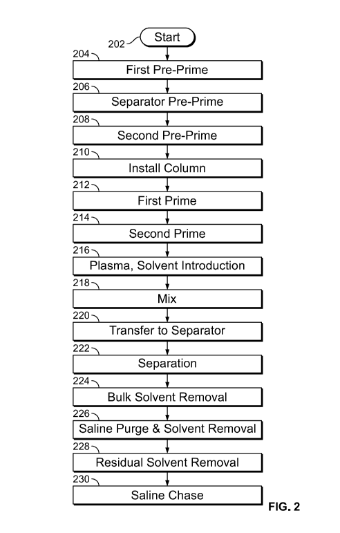
detail below. FIG. 2 is a flow chart illustrating an exemplary process for
separating modified
HDL, in accordance with some embodiments of the present specification. The
method described
in context of FIG. 2 may be implemented using system components 100 described
in context of
FIG. 1. At 202, a plasma delipidation process is started once the bags and
tubing sets are
connected in place, as described in FIG. 1. At 204, a first priming fluid pre-
primes various fluid
lines. In embodiments, fluid lines include the tubing sets and any other
channels for transporting
the fluids between the system's components.
In some embodiments, the present specification includes a computing device
with an
input/output controller, at least one communications interface and system
memory. The system
memory includes at least one random access memory (RAM) and at least one read-
only memory
(ROM). These elements are in communication with a central processing unit
(CPU) to enable
operation of the computing device. In various embodiments, the computing
device may be a
conventional standalone computer or alternatively, the functions of the
computing device may be
distributed across multiple computer systems and architectures. In some
embodiments, execution
of sequences of programmatic instructions enables or causes the processor to
perform various
functions and processes. In alternate embodiments, hard-wired circuitry may be
used in place of,
26
CA 03083194 2020-05-20
WO 2019/104237
PCT/US2018/062339
or in combination with, software instructions for implementation of the
processes of systems and
methods described in this specification. Thus, the systems and methods
described are not limited
to any specific combination of hardware and software.
In some configurations, the embodiments described in the present specification
include a
controller having at least a processor or processing circuitry and a system
memory that is in data
communication with at least one of the basic components of the system of the
present
specification to control or automate operation of the system, including, but
not limited to:
= One or more fluid inputs;
= One or more mixing devices that may be used to mix fluid from a fluid
input and
solvent from a solvent input;
= One or more valves that may be used to control the flow of a fluid, a
solvent or a
fluid-solvent mixture;
= One or more valves that may be used to control the flow of fluid from a
fluid input
and to control the flow of solvent from a solvent input;
= One or more valves that may be used to control the flow of a fluid-solvent
mixture
through tubing and to a separator;
= One or more separators for performing bulk solvent separation and valves
associated
therewith;
= One or more pressure sensors and/or valves positioned in the flow stream
to control
the flow of the second layer to the solvent extraction device;
= One or more glucose inputs and valves associated therewith;
= One or more saline inputs and valves associated therewith;
= One or more solvent extraction devices; and/or
= One or more pumps, which may be a peristaltic, roller, or rotary pump.
FIG. 3A illustrates a bag 355 containing the priming fluid. In some
embodiments, the
priming fluid for the first priming is saline. Saline prepares the system by
flushing the fluid
flow-path (lines) between bag 355 and a second waste container 365. The fluid
flow path
flushed at this step includes a Fluid Flow Path 1 (FFP1) comprising line 380
between bag 355
and a line 321 where line 321 is the fluid flow path between the separator and
a prime connector
tube 370, a line 382 between prime connector tube 370 and the pump 350, and a
line 384
extending between the pump and second waste container 365. FFP1 is not is
communication
27
CA 03083194 2020-05-20
WO 2019/104237
PCT/US2018/062339
with inputs 305, 310, 360, mixer 320, first waste container 335, and output
container 345. In
embodiments, the pump 350 functions to draw the priming fluid towards the
prime waste or
second waste container 365. In embodiments, second waste container 365 is
configured to
collect the prime waste.
In embodiments, at the preliminary priming stage, a solvent extraction device
is separate
from the system. The solvent extraction device may be a charcoal column that
is subsequently
added to the system and used to extract a solvent from plasma that contains
modified HDL
particles. The solvent extraction device is substituted with prime connector
tube 370 between
the fluid lines 321 and 382, between bag 355 and second waste container 365.
Pre-priming the
fluid lines ensures that air is substantially removed from the fluid lines.
Later when the solvent
extraction device is connected, the absence of air safeguards the function of
the solvent
extraction device. In embodiments, the solvent extraction device is a charcoal
column
comprising coated beads of charcoal. The substantial or material presence of
air interferes with
the efficiency and surface area of the charcoal column. In embodiments, once
the pump is closed,
it does not allow for backflow of fluids. At this stage, valves 315c, 315e,
and 315g, along FFP1
are open to facilitate passage and direct the flow of priming fluid from bag
355 to second waste
container 365 containing the prime waste. Other valves (315, 316, 315a, 315b,
315d, 315f, and
330) remain closed to prevent passage of the saline to other parts of the
lines, and therefore FFP1
is not in fluid communication with inputs 305, 310, 360, mixer 320, first
waste container 335,
and output container 345.
Following step 204, valves 315d and 330 are opened to facilitate passage of
priming fluid
from bags 360 to separator 325, while the other valves (315, 316, 315a, 315b,
315c, 315e, 315f,
and 315g) remain closed. At 206, a priming fluid pre-primes various fluid
lines towards a
separator 325. FIG. 3B illustrates at least two bags 360 containing the
priming fluid. In
embodiments, the priming fluid for priming the lines to separator 325 is
saline. The saline
prepares the system by flushing the lines between bags 360 and separator 325.
The fluid flow
paths flushed at this step may include line 380 between bags 360 and line 321,
and line 386
extending from separator 325 to line 321. Therefore, a second fluid flow path
(FFP2) may be
defined as the path including line 380 between bags 360 and line 321, and line
386 extending
from separator 325 to line 321. FFP2 does not include fluid paths to inputs
305, 310, and 355,
mixer 320, prime connector tube 370, pump 350, first waste container 335,
second waste
28
CA 03083194 2020-05-20
WO 2019/104237
PCT/US2018/062339
container 365, and output container 345. The solvent extraction device is
still separate from the
system.
Following step 206, valve 315d remains open, valves 315e and 315g are
additionally
opened, while all other valves (315, 316, 315a, 315b, 315c, 315f, and 330)
remain in order to
facilitate fluid flow along a third fluid flow path (FFP3). FFP3 may be
defined as the path of
fluid from bags 360, through prime connector tube 370, to second waste
container 365. FFP3 is
not in fluid communication with inputs 305, 310, and 355, mixer 320 separator
325, first waste
container 335, and output container 345. At 208, a second pre-priming
operation is performed in
the various fluid lines of the system through FFP3. Referring to FIG. 3C, at
this stage, priming
fluid from bags 360 are transported through valves 315d and 315e, through
prime connector tube
370, and through valve 315g, toward second waste container 365, while all
other valves remain
closed. Step 208 is concluded with presence of priming fluids in the main
lines of the system,
which include line 380, line 321, line 386, line 382, and line 384.
Following step 208, the priming fluid transported through the fluid lines is
drained into
second waste container 365, which is configured to collect prime waste. All
the valves (315, 316,
315a, 315b, 315c, 315d, 315f, 315e, 315g, 330) are then closed. Therefore
there is no path for
flow of fluids. The prime connector tube 370 is clamped and removed from the
fluid line. At
210, a solvent extraction device is installed into the system by replacing the
prime connector tube
370. Referring to FIG. 3D, a solvent extraction device 340 is installed at the
location within the
fluid line, between lines 321 and 382, where prime connector tube 370 was
originally placed.
Fluid lines (lines 321, 380, 382, 384, and 386) between bags 355 and 360,
separator 325, and
second waste container 365 are pre-primed, that is, they are primed before
installing solvent
extraction device 340.
Following step 210, valves 315c, 315e, and 315g are opened while all other
valves (315,
.. 316, 315a, 315b, 330, 315d, 315f) remain closed, which defines a fourth
fluid flow path (FFP4)
extending from input 355, through solvent extraction device 340, to second
waste container 365.
FFP4 is not in fluid communication with inputs 305, 310, 360, mixer 320,
separator 325, first
waste container 335, and output container 345. At 212, a first priming is
performed of the
various fluid lines. Referring to FIG. 3E, priming fluid from bag 355 is
depleted and transported
through FFP4 comprising valves 315c and 315e, through solvent extraction
device 340, valve
29
CA 03083194 2020-05-20
WO 2019/104237
PCT/US2018/062339
315g, and into second waste container 365. The fluid flow paths that are
primed at this step
include lines 380, 321, 382, and 384.
Following step 212, valve 315d is opened, valves 315e and 315g remain open,
while all
other valves (315, 316, 315a, 315b, 315c, 330, 315f) remain closed, which
defines a fifth fluid
flow path (FFP5) extending from inputs 360, through solvent extraction device
340, to second
waste container 365. FFP5 is not in fluid communication with inputs 305, 310,
355, mixer 320,
separator 325, first waste container 335, and output container 345. At 214, a
second priming is
performed of the various fluid lines through FFP5. Referring to FIG. 3F,
priming fluid from
bags 360 is transported through valves 315d, 315e, through solvent extraction
device 340, valve
315g, and into second waste container 365. The fluid flow paths that are
primed at this step
include lines 321, 380, 382, and 384.
At the conclusion of steps 212 and 214, all main fluid lines including lines
321, 380, 382,
and 384, separator 325 and solvent extraction device 340 are primed. In
embodiments, fluid
lines extending from bottom of separator 325 to second waste container 365,
configured to
contain prime waste, is filled with priming fluid. Priming also results in
removal of small
particulates from solvent extraction device 340.
Following step 214, valve 315 is opened and all other valves (316, 315a, 315b,
315c,
315d, 315e, 315f, 315g, and 330) are closed, defining a sixth fluid flow path
(FFP6) from input
305 to mixer 320. FFP6 is not in fluid communication with bag, 310, separator
325, first waste
container 335, inputs 310, 355, 360, solvent extraction device 340, pump 350,
second waste
container 365, and output container 345. At 216, the plasma fluid and the
solvent are introduced
one after the other, into a mixing device of the system. In embodiments, a
blood fraction of the
patient is obtained, which in a still further embodiment is plasma. The
process of blood
fractionation is typically achieved by filtration, centrifuging the blood,
aspiration, or any other
method known to persons skilled in the art. Blood fractionation separates the
plasma from the
blood. In an embodiment, blood fractionation is performed remotely. In one
embodiment, blood
is withdrawn from a patient in a volume sufficient to produce about 12 ml/kg
of plasma based on
body weight. During the fractionation process, the blood can optionally be
combined with an
anticoagulant, such as sodium citrate, and centrifuged at forces approximately
equal to 2,000
times gravity. The blood is separated into plasma and red blood cells using
methods commonly
known to one of skill in the art, such as plasmapheresis. In an embodiment,
the red blood cells
CA 03083194 2020-05-20
WO 2019/104237
PCT/US2018/062339
are then aspirated from the plasma. In one embodiment, the process of blood
fractionation is
performed by withdrawing blood from the patient with the cardiovascular and/or
related disease,
and who is being treated by the physician. In an alternative embodiment, the
process of blood
fractionation is performed by withdrawing blood from a person other than the
patient with the
cardiovascular and/or related disease who is treated by the physician.
Therefore, the plasma
obtained as a result of the blood fractionation process may be either
autologous or non-
autologous.
Subsequent to fractionation, the red blood cells are either stored in an
appropriate storage
solution or, preferably, returned to the patient during plasmapheresis.
Physiological saline, 5%
albumin, or other suitable fluid may also optionally be administered to the
patient to replenish
volume. If the blood was obtained from an individual other than the patient,
the cells are
returned to that individual, who can also be referred to as the donor.
Plasma obtained from blood is usually a straw-colored liquid that comprises
the
extracellular matrix of blood cells. Plasma is typically 95% water, and
contains dissolved
proteins, which constitute about 6-8% of plasma. The plasma also contains
glucose, clotting
factors, electrolytes, hormones, carbon dioxide, and oxygen. The plasma has a
density of
approximately 1006 kg/m3, or 1.006 g/ml.
In some alternate embodiments, Low Density Lipoprotein (LDL) is also separated
from
the plasma. Separated LDL is usually discarded. In alternative embodiments,
LDL is retained in
the plasma. In accordance with embodiments of the present specification, blood
fraction or
plasma obtained includes plasma with High Density Lipoprotein (HDL), and may
or may not
include other protein particles. In embodiments, autologous or non-autologous
plasma collected
from the patient or donor, respectively, is subsequently treated via an
approved plasmapheresis
device. The plasma may be transported using a continuous or batch process.
Referring to FIG. 3G, a plasma input bag 305 contains the plasma that will be
treated by
the various embodiments of the present specification. The plasma is
transported from bag 305,
along FFP6, through a valve 315, into a mixing device 320.
Following transportation of plasma from bag 305 to mixing device 320, valve
315 is
closed and valve 316 is opened, while all the other valves (315a, 315b, 315c,
315d, 315e, 315f,
315g, 330) remain closed, thus defining a seventh fluid flow path (FFP7) from
bag 310 to mixing
device 320. FFP7 is not in fluid communication with bag 305, separator 325,
first waste
31
CA 03083194 2020-05-20
WO 2019/104237
PCT/US2018/062339
container 335, inputs 310, 355, 360, solvent extraction device 340, pump 350,
second waste
container 365, and output container 345. Referring to FIG. 3H, a solvent input
bag 310 contains
the solvent. The solvent is transported along FFP7, from bag 310, through a
valve 316, into
mixing device 320. The solvent is used for extracting lipids from the plasma
fluid or from
particles within the plasma fluid. Suitable extraction solvents include
solvents that extract or
dissolve lipid, including but not limited to phenols, hydrocarbons, amines,
ethers, esters, alcohols,
halohydrocarbons, halocarbons, and combinations thereof. Examples of suitable
extraction
solvents are ethers, esters, alcohols, halohydrocarbons, or halocarbons which
include, but are not
limited to di-isopropyl ether (DIPE), which is also referred to as isopropyl
ether, diethyl ether
(DEE), which is also referred to as ethyl ether, lower order alcohols such as
butanol, especially
n-butanol, ethyl acetate, dichloromethane, chloroform, isoflurane, sevoflurane
(1,1, 1,3, 3,3-
hexafluoro-2- (fluoromethoxy) propane-d3), perfluorocyclohexanes,
trifluoroethane,
cyclofluorohexanol, and combinations thereof In an embodiment, a mix of
Sevoflurane and n-
butanol is used as the solvent. In an embodiment a volume ratio of Sevoflurane
and n-butanol
used is 95:5. In various embodiments, the plasma and the solvent are
transported in any order.
While transporting the plasma and the solvent to mixing device 320, the valves
corresponding to
bags containing the plasma (valve 315) and the solvent (valve 316) are
respectively open. All
other valves (315a, 315b, 315c, 315d, 315e, 315f, 315g, and 330) remain
closed.
Following step 216, once the plasma and the solvent are in mixing device 320,
all the
valves (316, 316, 315a, 315b, 315c, 315d, 315e, 315f, 315g, 330) are closed.
At 218, the plasma
and the solvent, which are present together within the mixing apparatus are
processed by a
mixing operation. In an embodiment, the solvents used include either or both
of organic solvents
sevoflurane and n-butanol. In embodiments, the solvent is optimally designed
such that only the
HDL particles are treated to reduce their lipid levels and LDL levels are not
affected.
The mixing process includes factoring in variables such as the solvent
employed, mixing
method, time, and temperature. Choice of a mixing method may also affect some
system
requirements, such as but not limited to functional requirements, packaging
requirements, cost,
and environmental requirements. Additional variables that may be considered in
system design
are as follows:
1. Priming. Whether the system can handle priming so that it can be primed and
ready
for a process.
32
CA 03083194 2020-05-20
WO 2019/104237
PCT/US2018/062339
2. Continuous or Interrupted Flow. Whether the system has to be continuous in
nature
(continuously separates plasma and inputs replacement fluid in parallel) or
can handle
discrete amounts of liquid (batch flow).
3. Closed Loop Control. Whether the system has to be monitored or can be
validated by
process.
4. Variable Flow. Whether the system can handle various ranges of flow.
5. Hold-up Volume. This is the amount of fluid or blood that remains in the
circuit after
the process is complete, as it is desirable to have as little blood or fluid
outside of the
patient at any given time and so that the plasma that will be returned to the
patient is
not overdiluted.
6. Mixing Control. Whether the system allows for controlling the level, speed
or extent
of mixing.
7. Plasma Range. Whether the system can handle different types of plasma,
including
normal plasma, high LDL plasma, high triglyceride plasma, and other types of
plasma.
8. Packaging Requirements. Whether a hospital or blood bank could accommodate
the
footprint of the system and its associated components, including disposables
and
hardware.
9. Environmental Requirements. Whether the system could be deployed in a
variety of
settings with respect to operating noise/vibration and hardware durability
(for
example, whether it can be deployed in bloodbanks or hospitals).
10. Cost. Whether the system can be manufactured in a cost-effective manner
(for
example, no high cost, high precision connectors).
Different mixing methods provided different results in terms of remaining
cholesterol,
remaining phospholipids, remaining Apo-B, and remaining Apo-A, within the
delipidated
plasma obtained after the mixing. The mixing methods employed in the present
specification
take into account a plurality of variables that, when combined, achieve an
ideal mixing
environment for optimal selective delipidation. By way of background, several
mixing methods,
as are well-known to those of ordinary skill in the art were initially
employed with little to no
success. These methods included continuous vortex mixing, mixing using a
static mixer, mixing
using a silly straw mixer, and mixing using a rotating cylinder.
33
CA 03083194 2020-05-20
WO 2019/104237
PCT/US2018/062339
Continuous vortex type of mixing involves using a vortexer to mix smaller
quantities of
liquid. When a test tube or other container is pressed into the rubber cup of
the vortexer, the
motion is transferred to the liquid inside, creating a fluid vortex or
whirlpool in an off-center
rotation. Because the speeds achieved are close to 2500 rpm, the end result
could be
"overdelipidation", or complete delipidation of both HDL and LDL. As discussed
above, it is
not desirable to delipidate LDL.
A static mixer is a plate-type mixer or a mixer comprising mixing elements
contained
within an elongated housing that effectuates movement of a tube containing a
mixture or mixture
of fluids, where the movement is typically sideways from one side to another.
It is typically
employed for continuous mixing. This method of mixing does not work as it 1)
involves direct
connection to the patient for serial apheresis and delipidation and also
results in
"overdelipidation", or complete delipidation of both HDL and LDL. As discussed
above, it is
not desirable to delipidate LDL
The "silly straw" method of mixing was designed as a coiled tube (a tubing set
wrapped
around a stick) through which a fluid mixture flows continuously creating a
Taylor vortex. A
continuous flow of plasma and solvent in a 2:1 solvent to plasma ratio was
used. This method
proved to be entirely ineffective. One theory is that in order to effectively
selectively delipidate,
the plasma and solvent mixture needs to be in full contact at a specified
ratio, for a specified
amount of time and that an instantaneous flow-through process could not
achieve this
equilibrium.
Mixing using a rotating cylinder involves a tube containing the mixture that
rotates
around its axis (similar to the movement of a record on a turntable) to mix
the fluids within the
tube. In using this process, the fluid tumbles from the top to the bottom of
the test tube. While
the method was not optimal for selective delipidation as described in the
present specification, a
novel mixing bag of specific geometry and size was designed and implemented.
The system of the present specification, and in particular, the mixing sub-
system is
designed so that it can be primed and ready for a process. In addition, the
system of the current
specification can handle fluid processing in batches without the need for
continuous flow. The
system of the present specification advantageously does not require closed
loop control. Once
the parameters (flow rate, volume) are established, the system is gravity
based and operates
accordingly. Optionally, a charcoal column is employed to further ensure that
all solvent is
34
CA 03083194 2020-05-20
WO 2019/104237
PCT/US2018/062339
removed. The system of the present specification can also accommodate various
ranges of fluid
flow. Because the system of the present specification is a stand-alone system
(meaning that
apheresis is not integrated), the issue of hold-up volume becomes a non-issue.
The system of the
present specification also allows for controlling the level of mixing by
determining the speed of
the mixer and using a mixing bag with an appropriate volume and geometry.
Further, the system
of the present specification is designed to be able to handle a wide and
infinite range of plasma
that can be treated by the system, including, but not limited to normal
plasma, high LDL plasma,
high triglyceride plasma, and other types of plasma. The system of the present
specification has
low to minimal footprint, is readily and easily deployable in a variety of
environments with
minimal noise impact. In addition, the system of the present specification can
be manufactured
in a cost-effective manner.
Referring to FIG. 31, mixing device 320 may be a bag used for mixing the
plasma and the
solvent. In embodiments, mixing device 320 includes both an orbital mixer and
a mixing bag,
and is placed at an angle within the system. In one embodiment, the mixing bag
is placed
horizontally over the orbital mixing device, because this position may receive
the most optimal
orbital mixing action for the fluid contained in the bag, as most of the fluid
would gravitate
towards the bottom. The bag and its corners can be used to impart energy. The
mixing bag,
using an angled platform as described below may be placed at a slight angle to
enable draining of
the fluids. The angle may range from 0 degrees (completely vertical) to 90
degrees (completely
horizontal). In one embodiment, the platform upon which the mixing bag rests
is placed at an
angle of 18.2 degrees. In one embodiment, mixing device 320 is of a circular
shape. In another
embodiment, mixing device 320 is of a rectangular shape.
FIG. 7 illustrates an exemplary mixing device (bag) 700, in accordance with
embodiments described in context of FIG. 31. Bag 700 is of a rectangular
shape, comprising a
section 702 where plasma and solvent fluid may be received through an input
pipe 708. Section
702 has at least five edges and is at the center of bag 700. Section 702 is
surrounded by sealed
sections of bag 700. One of the edges of bag 700 includes a rectangular sealed
section 704. Two
mutually inclined edges, opposite to the edge along section 702, include
triangular sealed
sections 706a and 706b. Each sealed section 704, 706a, and 706b, includes at
least one hanger
hole, such as holes 712. Section 702 includes an output pipe 714 positioned
between triangular
sealed section 706a and 706b, to enable letting out of the mixture.
CA 03083194 2020-05-20
WO 2019/104237
PCT/US2018/062339
FIG. 8A illustrates a side view of shaker angle brackets 800 that are used to
position
mixing device 320 within the system, in accordance with some embodiments of
the present
specification. FIG. 8B illustrates a another side view of shaker angle
brackets 800 that are used
to position mixing device 320 within the system, in accordance with some
embodiments of the
present specification. FIG. 8C illustrates a perspective view of shaker angle
brackets 800 that
are used to position mixing device 320 within the system, in accordance with
some embodiments
of the present specification. Referring simultaneously to FIGS. 8A, 8B, and
8C, the mixing bag
used to perform the mixing operation may be placed over an orbital mixer,
which is fitted within
the system with the help of brackets 800. In embodiments, brackets 800 are
manufactured from
Aluminum. In one embodiment, the Aluminum used for making brackets 800 is
0.060 inches
thick. Referring simultaneously to FIGS. 8A, 8B, and 8C, brackets 800 include
two parts 802
and 804, which mirror each other. In one embodiment, bracket 802 is placed on
the left and
bracket 804 is placed opposite to bracket 802on the right. A mixing device,
such as device 320
of FIG. 31, is positioned on brackets 802 and 804. Holes 806 on both brackets
802 and 804
enable fixing the mixing device. In one embodiment, the mixing device provides
a platform for
placing the mixing bag, such as bag 700 of FIG. 7. Each bracket has two
opposing sides
connected by a flat surface between them. A top side 808 of each bracket is
inclined at an angle
for placing the mixing bag. In embodiments, the angle is in the range of 0 to
90 degrees. In one
embodiment, the angle is 18.2 degrees, relative to a horizontal bottom side
810. The incline
provided by top side 808 enables placing the mixing device, and therefore the
mixing bag at an
inclination, for an optimal mixing operation. Each edge 808 and 810 is bent in
two ways to
created angled brackets 802 and 804. The bent portions include holes 806 that
enable fixing the
mixing device with brackets 800.
In one embodiment, mixing device 320 has a capacity of 300 milliliters (ml).
In one
embodiment, mixing device 320 is configured to mix approximately 100 ml of
plasma with the
solvent during a single mixing operation. In one embodiment, solvent and
plasma are mixed in a
volume ratio of 2:1. For example, 100 ml of plasma is mixed with 200 ml of the
solvent. In
another embodiment, the solvent and plasma are mixed in a volume ratio of 1:1.
Solvent type, ratios and concentrations may vary in this step. Acceptable
ratios of
solvent to plasma include any combination of solvent and plasma. In some
embodiments,
(volume) ratios used are 2 parts plasma to 1 part solvent, 1 part plasma to 1
part solvent, or 1 part
36
CA 03083194 2020-05-20
WO 2019/104237
PCT/US2018/062339
plasma to 2 parts solvent. In an embodiment, when using a solvent comprising
95 parts
sevoflurane to 5 parts n-butanol, a ratio of two parts solvent per one part
plasma is used.
Additionally, in an embodiment employing a solvent containing n-butanol, the
present
specification uses a ratio of solvent to plasma that yields at least 5% n-
butanol in the final
solvent/plasma mixture. In an embodiment, a final concentration of n-butanol
in the final
solvent/plasma mixture is 3.33%. In embodiments, the final concentration of n-
butanol in the
resultant solvent/plasma mixture may vary and may be dependent on the solvent
to plasma ratio,
which may also vary. The plasma may be transported to the mixing device using
a continuous or
batch process. Further various sensing means may be included to monitor
pressures,
temperatures, flow rates, solvent levels, and the like. The solvents dissolve
lipids from the
plasma. In embodiments of the present specification, the solvents dissolve
lipids to yield treated
plasma that contains modified HDL particles with reduced lipid content. The
process is designed
such that HDL particles are treated to reduce their lipid levels and yield
modified HDL particles
without destruction of plasma proteins or substantially affecting LDL
particles. It should be
noted that there is no clinically significant decrease in blood constituents
post-plasmapheresis.
In one embodiment, mixing device 320 is operated to mix the plasma solvent
mixture for
60 seconds with an average mixing plasma batch volume of 99 7.5 ml.
In various embodiments, various energy measurements are provided as input to
operate
mixing device 320. Energy is introduced into the system in the form of varied
mixing methods,
time, and speed. A combination of the mixing parameters such as but not
limited to the volume
ratio of solvent to plasma, shape of the mixing device 320, and the amount of
energy input used
to operate mixing device 320, directly affect the success of the mixing
operation to achieve
delipidated HDL particles in the plasma. In one example, a solvent to plasma
ratio of 2:1, for a
batch of 100 ml plasma, mixed for 60 seconds, in a rectangular mixing device,
using an energy
input of 200 RPM does not delipidate the HDL particles from the plasma. In
another example, a
solvent to plasma ratio of 2:1, for a batch of 100 ml plasma, mixed for 60
seconds, in a large
square mixing device, using an energy input of 400 RPM also does not
delipidate the HDL
particles from the plasma. Therefore, multiple parameters affect the success
of delipidating HDL
particles from the plasma. The effect of varying the different parameters is
described in the
subsequent sections, and in context of experiments illustrated in FIGS. 4, 5,
and 6.
37
CA 03083194 2020-05-20
WO 2019/104237
PCT/US2018/062339
Referring back to step 218 of FIG. 2, and FIG. 31, the plasma and the solvent
interact
with each other within mixing device 320 to the extent that HDL particles are
delipidated, while
LDL particles are not. The process is therefore termed as selective
delipidation. In
embodiments, the mixing is performed in order to achieve at least 80%
delipidation of HDL
particles.
After the mixing, valve 315a is opened while all the other valves (315, 316,
315b, 315c,
315d, 315e, 315f, 315g, 330) remain closed, thus defining an eighth fluid flow
path (FFP8)
between mixing device 320 and separator 325. FFP8 is not in fluid
communication with bags
305, 310, 355, 360, waste containers 335, 365, solvent extraction device 340,
pump 350, and
output container 345. At 220, once the mixing operation is completed, the
solvent plasma
mixture is transferred to a separator along FFP8, where the plasma and the
solvent are separated
by gravity. Referring to FIG. 3J, mixture of solvent and plasma is dropped
down through a valve
315a in to a separator 325. The mixture remains in separator 325 until the
solvent settles at the
bottom of separator 325. The plasma is separated and remains in a layer above
the solvent. The
solvent employed is preferably of a higher density than plasma, and therefore
settles at the
bottom.
In embodiments, steps 216, 218, and 220 are performed iteratively, in batches,
until
separator 325 is filled to its capacity. Once the separator is filled to its
capacity, all the valves
(315, 316, 315a, 315b, 315c, 315d, 315e, 315f, 315g, 330) are closed. At 222,
and referring to
FIG. 3K, the collected mixture of plasma and solvent in separator 325 is
allowed to stand for a
period of time, until the solvent separates and settles at the bottom of
separator 325. In
embodiments, the period of time is dependent upon the time it takes for the
solvent to fully
separate without a loss or sacrifice in the amount of plasma. In one
embodiment, the mixture is
allowed to stand for approximately 30 minutes. In embodiments, separator 325
has a cone-
shaped bottom that enables easy removal of bulk solvent in a subsequent step.
Following the separation, valve 315b is opened to define a ninth fluid flow
path (FFP9)
from separator 325 to first waste container 335. FFP9 is not in fluid
communication with bags
305, 310, 355, 360, mixer 320, second waste container 365, solvent extraction
device 340, pump
350, and output container 345. At 224, bulk solvent is removed from the
separator 325 along
FFP9. Referring to FIG. 3L, bulk solvent that has settled at the bottom
portion of separator 325
flows to a first waste container 335 through a valve 315b, which, when open
allows fluid to flow
38
CA 03083194 2020-05-20
WO 2019/104237
PCT/US2018/062339
freely using gravity. In other embodiments, a pump may be employed to remove
the solvent.
Cone-shaped bottom of separator 325 aids easy removal of bulk solvent. Valve
315b is closed
after bulk solvent has been moved through it and before the plasma from
separator 325 reaches
valve 315b.
In embodiments, a weight of separator 325 is known, in addition to weight of
the plasma
and of the solvent. In embodiments, the weight of the separator bag is
continuously monitored.
With this information, valve 315b is closed as soon as the amount of solvent
removed from
separator 325 corresponds to the known weight of the solvent. The weight of
the solvent that
flows to the first waste container 335 is, in an embodiment, indirectly
monitored, because the
amount of solvent that is added to the system and the amount of solvent
present in the separator
waste bag are known. In addition, the residual concentration of solvent that
is in the plasma is
based on validation of system parameters and a validated analysis of residual
solvent
concentrations via GC over many process runs.
Once valve 315b is closed, valves 330, 315e, and 315g are opened while all
other valves
(315, 316, 315a, 315c, 315d, 315f, 330) remain closed, thus defining a tenth
fluid flow path
(FFP10). FFP10 is not in fluid communication with bags 305, 310, 355, 360,
mixing device 320,
first waste container 335, second waste container 365, and output device 345.
At 226, and
referring to FIG. 3M, a pump 350 is turned on and valves 330 and 315e are
opened in order to
pull plasma from separator 325 through fluid line 321 towards solvent
extraction device 340,
along FFP10. During this operation, initially a valve 315g is simultaneously
open. Valve 315g
is placed between solvent extraction device and second waste container 365. As
the pump pulls
the fluid present in lines 321 from separator 325 through solvent extraction
device 340, priming
fluid that was initially present in lines 321, 382, and 384, extending between
separator 325 and
second waste container 365, is pushed, or chased, further ahead in the lines
by the plasma being
pulled through valve 315g, towards second waste container 365 configured to
contain prime
waste. Once plasma (pulled by pump 350) reaches valve 315g, which is
determined using both
the tube length and the volume of fluid passed through the pump per
revolution, the valve 315g
is closed so that priming fluid is separated from plasma. This ensures that
the plasma is not
diluted and additional fluids are not collected along with the plasma that
will subsequently be
.. delivered back to the patient.
39
CA 03083194 2020-05-20
WO 2019/104237
PCT/US2018/062339
Subsequently, valve 315f is opened in addition to already open valves 330,
315e, while
all other valves (315, 316, 315a, 315b, 315c, 315d, 315g) remain closed, thus
defining another
fluid flow path (FFP11) from separator 325, through solvent extraction device
340, to output
device 345. At 228, and referring to FIG. 3N, pump 350 further pulls plasma
along FFP11, from
.. separator 325 through valves 330 and 315e, through solvent extraction
device 340, and through a
valve 315f, towards and into an output plasma container 345. As plasma moves
through solvent
extraction device 340, charcoal in solvent extraction device 340 absorbs and
therefore extracts
any remaining solvent from the plasma.
After extracting the delipidated plasma in to output container 345, valve 330
is closed
.. along with valves 315, 316, 315a, 315b, 315c, 315g, and valve 315d is
opened along with open
valves 315e and 315f, thus defining another fluid flow path FFP12 from bags
360 through
solvent extraction device 340, to output device 345. FFP 12 is not in fluid
communication with
bags 305, 310, 355, mixing device 320, separator 325, first waste container
335, and second
waste container 365. At 230, and referring to FIG. 30, once plasma is pulled
out from separator
325 completely, pump 350 is still operated until priming fluid from bags 360
along FFP12 to
follow or chase the plasma in the lines 380, 321, 382, and 384, through valve
315e, through
solvent extraction device 340, and through valve 315f. Pump 350 is stopped
once the priming
fluid, chasing the plasma, reaches a position in the fluid line which is just
before reaching output
plasma container 345. In an embodiment, 150 mL of priming fluid is used to
further chase the
plasma into the plasma output bag 145/345 to ensure full recovery of the
delipidated plasma. In
an embodiment, chasing the fluid flow to the prime waste occurs to the point
where pump 350
reaches a specific number of revolutions that is indicative of the plasma
volume that has flowed
through the system. Thus, the revolutions of the pump control how much fluid
is in the prime
waste or second waste container 345. Pump 350 is stopped to ensure that as
much of the
delipidated plasma that available in the system is collected in container 345,
while the collected
plasma is saved from unnecessary dilution by priming fluids. In embodiments,
pump 350 is
stopped automatically by the system based on the amount of plasma collected,
which
corresponds to the known amount of input plasma. In embodiments, the
configurations of the
disposable elements within the system are employed to program the system to
automatically stop
pump 350. In an embodiment, the tubing sets are of a known length and
diameter. In addition,
CA 03083194 2020-05-20
WO 2019/104237
PCT/US2018/062339
the volume of solvent at the bottom of separator bag 325 is also known in
addition to the amount
of plasma.
The extracted modified HDL plasma solution has an increased concentration of
pre-beta
HDL. It is estimated that the modified HDL in the delipidated plasma, has
approximately 80-
85% of pre-0 particles, and about 15% of a HDL particles. Concentration of pre-
beta HDL is
greater in the modified HDL, relative to the original HDL that was present in
the plasma before
treating it with the solvent. Compared to the plasma solution originally
separated from the blood
fraction, which typically contains approximately 5% of pre-0 HDL particles,
the concentration of
pre-0 HDL particles is substantially increased.
At the end of this process, solvent waste is collected separately in first
waste container
135/335, and prime waste is collected in second waste container 165/365,
through their separate
waste streams. This is advantageous for many reasons. Primarily, it is more
expensive to
dispose of certain types of waste, such as solvent waste. If solvent waste is
"contaminated" with
or combined with other types of waste, the additional waste will have to be
disposed of in the
same costly manner as solvent waste. Prime waste, for example, which consists
of mostly saline
and/or glucose, can be directed to a normal hospital waste stream. If mixed
with solvent, the
prime waste will have to be diverted into the chemical waste disposal
channels, by default. By
separating out waste, each waste stream can be treated and disposed of
appropriately. In some
embodiments, the solvent waste can be treated or scrubbed to reclaim a pure
solvent so that it can
be re-used.
Examples of effect of varying multiple parameters are now explained briefly.
Among
various methods by which plasma may be delipidated, parameters affecting the
extent of
delipidation may be broadly identified as chemical and mechanical parameters.
Examples of
chemical parameters may include, but may not be limited to, plasma type
(bovine, human,
lipemic), plasma volumes, solvent type (n-butanol/DiPE or n-
butanol/sevoflurane, any other),
percentage of n-butanol present in the solvent, and solvent to plasma ratio.
Examples of some of
the mechanical parameters may include, a method of mixing (rocker table,
vortex, any other),
mixing duration, method of separation (gravity, centrifuge, any other),
separation time, and
centrifuge force.
For purposes of illustrating the effect of varying these parameters on the
extent of
delipidation, an experimental delipidation process was performed in a
laboratory setting. The
41
CA 03083194 2020-05-20
WO 2019/104237
PCT/US2018/062339
results, presented in table 400 of FIG. 4, are briefly discussed herein.
Referring to table 400, first
column 402 lists different embodiments in separate rows. Each embodiment
corresponds to a
unique combination of the parameters that affect the extent of delipidation.
The second column
404 lists the plasma type used for each embodiment. The plasma type was
selected from the
plasma of a human or that of a bovine. Column 406 lists the plasma volumes (in
milliliter) used
in each embodiment. Column 408 lists the type of solvent used. In most
embodiments, the
solvent type is either of n-Butanol and DiPe. Column 410 lists the percentage
of n-Butanol used,
which may also be inferred as an indication of the solvent ratio. Column 412
lists the solvent to
plasma ratio used in each embodiment. Column 414 lists the type of mixing
method used for
each embodiment. Column 416 lists the time for which the mixing process was
implemented.
Column 418 lists the chosen method for separation of the plasma and the
solvent. Column 420
lists the time for which the process of separation was performed for each
embodiment. Column
422 lists the amount of centrifugal force applied for each embodiment. Lastly,
column 424 lists
the results that show the variation across each embodiment, in the percentage
of lipids that
remain in the treated plasma.
Embodiment 1: About 10 milliliters (m1) of plasma derived from a human was
used. This
plasma was mixed with n-butanol/DiPE solvent. A solvent to plasma ratio of 2:1
was used. The
rocker table was used to perform the mixing operation, for about five minutes.
A centrifugal
force of 563 x G was applied for about two minutes to separate the delipidated
plasma from the
solvent. The effect of varying percentage of n-butanol in the solvent within a
range of 0% to
40% is that remaining lipids progressively decrease with an increase in the
quantity of n-butanol
in the solvent.
Embodiment 2: In another similar experiment, 10m1 of bovine plasma was mixed
with n-
butanol/DiPE solvent containing 25% n-butanol. The mixture was mixed using a
rocker table for
about five minutes. A centrifugal force of 563 x G was applied for about two
minutes to separate
the delipidated plasma from the solvent. The effect of varying the solvent to
plasma ratio in a
range of 0.25 to 10 is that a lower ratio, specifically within a range of 1 to
2, results in most
reduced lipid concentration in the delipidated solution.
Embodiment 3: In another similar experiment, 10m1 of human plasma was mixed
with n-
butanol/DiPE solvent containing 25% n-butanol, using a solvent to plasma ratio
of 2:1. Different
samples of the mixture were mixed using a rocker table and using a vortex.
Gravity separation
42
CA 03083194 2020-05-20
WO 2019/104237
PCT/US2018/062339
was used for about five minutes to separate some of the samples, as well as a
centrifugal force of
563 x G was applied for about two minutes to separate the delipidated plasma
from the solvent
for the remaining samples. The effect of different mixing methods and by
varying the duration
of mixing for both the methods used for separating (gravity and centrifuge) is
that there is a
variation on the concentration of lipids remaining in the delipidated plasma.
Embodiment 4: In yet another similar experiment, 10m1 of human plasma was
mixed
with n-butanol/DiPE solvent containing 25% n-butanol, using a solvent to
plasma ratio of 2:1.
The mixture was mixed using a rocker table for about five minutes. A range of
centrifugal force
was applied for about two minutes to separate the delipidated plasma from the
solvent. The
effect of varying the centrifugal force used for separation on the lipid
concentration remaining in
the delipidated plasma
FIG. 5 is a table 500 that lists another exemplary set of variables that may
affect the
delipidation process and resultant percentage selective delipidation and is
presented by way of
example only to show possible combinations of variables. The ideal results
from these
experiments include a substantial change in HDL concentration, no change in
LDL concentration,
preservation of Apo-Al, preservation of Apo-B, and preservation of
phospholipids, resulting in
selective delipidation of plasma. Referring to the table 500, the first column
502 lists the type of
solvent mix used. The constituents for the solvent solution may contain one or
more of
Sevoflurane (S), n-butanol (N), DiPE (D), and Isofluorane (I). The second
column 504 (Solvent
Ratio) lists the ratio of the constituents of the solvent that may be used in
the solvent solution,
corresponding to the first column. The third column 506 (Plasma: Solvent
Ratio) lists the
proportion of the plasma and the solvent that may be mixed together for the
delipidation. The
fourth column (Mix Method) 508 states the corresponding mixing method that may
be used. The
fifth column (Time) 510 provides the corresponding duration for which mixing
can be performed.
The sixth column (Sep. Method) 512 lists the method used for separation of the
delipidated
plasma and the solvent. The two methods commonly used for separation are
gravity separation
(GS) and centrifugal separation (CF), in the embodiments of the present
specification.
FIG. 6 is a table 600 that provides another exemplary set of variables that
may be used
for normal plasma and lipemic IV plasma using different solvents and different
methods of
separation. A first column 602 (Plasma) lists the type of plasma (normal or
lipemic IV) used in
each embodiment, where each row corresponds to a different embodiment. Column
604
43
CA 03083194 2020-05-20
WO 2019/104237
PCT/US2018/062339
(solvents) lists the type of solvent or solvent mixture used corresponding to
each embodiment.
Column 606 (Ratio) lists the ratios of constituents in a solvent mixture for
each embodiment.
Column 608 (P:S) lists the plasma to solvent ratio corresponding to each
embodiment. Column
610 (Volume) lists the volume of the plasma used for each embodiment. Column
612 (S
Volume) lists the volume of the solvent/solvent mixture used for each
embodiment. The
volumes of the plasma and the solvent/solvent mixture corresponds to the ratio
listed in column
608. Column 614 (Mix Method) lists the method of mixing used for each
embodiment. Column
616 (Time) lists the duration for which the mixing was performed. Column 618
(Separation)
lists the method used for separation (centrifugal or gravity separation) of
the plasma and the
solvent. Column 620 (time(min)) lists the duration (in minutes) for which the
separation process
was performed for each embodiment. Lastly, column 622 (Solvent Removal) lists
the type of
method used for solvent removal. As seen in table 600, a charcoal column was
used in all the
embodiments to remove the solvent.
In general, the present specification preferably comprises configurations
wherein all
inputs, such as input plasma and input solvents, disposable elements, such as
mixing bags,
separator bags, waste bags, solvent extraction devices, and solvent detection
devices, and output
containers are in easily accessible positions and can be readily removed and
replaced by a
technician.
To enable the operation of the above described embodiments of the present
invention, it
is preferable to supply a user of such embodiments with a packaged set of
components, in kit
form, comprising each component required to practice embodiments of the
present specification.
The kit may include an input fluid container (i.e. a high density lipoprotein
source container), a
lipid removing agent source container (i.e. a solvent container), disposable
components of a
mixer, such as a bag or other container, disposable components of a separator,
such as a bag or
other container, disposable components of a solvent extraction device (i.e. a
charcoal column),
an output container, disposable components of a waste container, such as a bag
or other container,
solvent detection devices, and, a plurality of tubing and a plurality of
valves for controlling the
flow of input fluid (high density lipoprotein) from the input container and
lipid removing agent
(solvent) from the solvent container to the mixer, for controlling the flow of
the mixture of lipid
removing agent, lipid, and particle derivative to the separator, for
controlling the flow of lipid
and lipid removing agent to a waste container, for controlling the flow of
residual lipid removing
44
CA 03083194 2020-05-20
WO 2019/104237
PCT/US2018/062339
agent, residual lipid, and particle derivative to the extraction device, and
for controlling the flow
of particle derivative to the output container.
In one embodiment, a kit comprises a plastic container having disposable
components of
a mixer, such as a bag or other container, disposable components of a
separator, such as a bag or
other container, disposable components of a waste container, such as a bag or
other container,
and, a plurality of tubing and a plurality of valves for controlling the flow
of input fluid (high
density lipoprotein) from the input container and lipid removing agent
(solvent) from the solvent
container to the mixer, for controlling the flow of the mixture of lipid
removing agent, lipid, and
particle derivative to the separator, for controlling the flow of lipid and
lipid removing agent to a
waste container, for controlling the flow of residual lipid removing agent,
residual lipid, and
particle derivative to the extraction device, and for controlling the flow of
particle derivative to
the output container. Disposable components of a solvent extraction device
(i.e. a charcoal
column), the input fluid, the input solvent, and solvent extraction devices
may be provided
separately.
The above examples are merely illustrative of the many applications of the
system of
present invention. Although only a few embodiments of the present invention
have been
described herein, it should be understood that the present invention might be
embodied in many
other specific forms without departing from the spirit or scope of the
invention. Therefore, the
present examples and embodiments are to be considered as illustrative and not
restrictive, and
the invention may be modified within the scope of the appended claims.