Note: Descriptions are shown in the official language in which they were submitted.
STAND-UP BAG
BACKGROUND
Field of the Invention
100011 Our invention relates to a storage bag. More specifically, our
invention relates to a plastic
storage bag that can be shifted between a flat configuration and a stand-up
configuration wherein
the bag can be easily filled.
Related Art
100021 Storage bags made from flexible plastic materials are well known. Such
plastic storage
bags are offered in a variety of sizes and can be used to contain a variety of
items, including
food, utensils, clothing, tools, etc. These storage bags often include a
zipperlike closure
mechanism to releasably seal the interior of the bag. Different types of
plastic storage bags with
closure mechanisms are sold by the assignee of the present application under
the 'ZIPLOCIO
trademark.
100031 It is desirable to configure a plastic storage bag such that a user can
set the hag in an
opened position with the bag standing upright and without the user having to
hold onto the bag.
That is, it is desirable for a plastic storage bag to stand upright, with its
closure mechanism
unsealed, without the user grasping the bag. In such an upright and opened
position, the user's
hands are free to fill the bag with items.
10004] Al other times, however, it is desirable for the plastic storage bag to
lie as flat as possible.
For example, when the bag is not being used, a flat bag may be more compactly
stored.
Date Recue/Date Received 2020-06-15
WO 2015/138559
PCT/US2015/019878
100051 In order
to provide a plastic storage bag that can stand upright without the user
holding onto the bag, a pleat or gusset is sometimes added to the bottom of
the bag. By
"pleat" or "gusset" we mean additional material provided between other
portions of the
bag, for example, a fold formed by doubling back the material forming the bag
on itself.
An example of such a pleat/gusset arrangement in a bag can be seen in U.S.
Patent No.
3,738,565. In addition to a pleat, a storage bag may be made thicker
throughout its sides
and bottom to more firmly support itself in an upright position. Both a pleat
and a thicker
bag, however, require the use of additional material to form the bag, thereby
increasing the
costs associated with manufacturing the bag. Moreover, a pleat and additional
material
reduce the ability of the bag to be made flat, for example, when not being
used and being
stored.
SUMMARY OF THE INVENTION
100061 In one aspect, our invention is directed to a storage bag
including a first
sidewall that includes at least one shift region that extends from near a
comer of the first
sidewall and a second sidewall directly connected to the first sidewall along
three sides of
the bag to form an interior of the bag with an opening thereto. The second
sidewall
includes at least one shift region that extends from near a corner of the
second sidewall.
The bag is shiftable about the at least one shift region of the first sidewall
and shiftable
about the at least one shift region of the second sidewall such that the bag
can be shifted
between (i) a flat configuration with the first and second sidewalls
positioned adjacent to
each other, and (ii) a stand-up configuration with the first and second
sidewalls separated
from each other. In the stand-up configuration, a substantially flat base is
formed for the
bag.
2
Date Recue/Date Received 2020-06-15
WO 2015/138559
PCT/US2015/019878
[0007] In another aspect, our invention is directed to a storage bag
including a
first sidewall that includes (i) a first shift region that extends from a
first corner of the first
sidewall, (ii) a second shift region that extends from the first corner of the
first sidewall,
(iii) a third shift region that extends from a second comer of the first
sidewall, and (iv) a
fourth shift region that extends from the second corner of the first sidewall,
and a second
sidewall connected to the first sidewall so as to form an interior of the bag
with an opening
thereto. The second sidewall includes (i) a first shift region that extends
from near a first
comer of the second sidewall, (ii) a second shift region that extends from
near the first
comer of the second sidewall, (iii) a third shift region that extends from
near a second
comer of the second sidewall, and (iv) a fourth shift region that extends from
near the
second corner of the second sidewall. The bag can be shifted between (i) a
flat
configuration with the first and second sidewalls positioned adjacent to each
other and (ii)
a stand-up configuration with the first and second sidewalls separated from
each other. In
the stand-up configuration, the bag is shifted about the first, second, third,
and fourth shift
regions of the first sidewall and about the first, second, third, and fourth
shift regions of
the second sidewall such that a substantially flat base is formed for the bag.
100081 In another aspect, our invention is directed to a storage bag
including a
first sidewall that includes (i) shift regions that extend from near a first
corner of the first
sidewall and (ii) shift regions that extend from near a second corner of the
first sidewall,
and a second sidewall directly connected to the first sidewall along three
sides of the bag
to form an interior of the bag with an opening thereto. The second sidewall
includes (i)
shift regions that extend from near a first corner of the second sidewall and
(ii) shift
regions that extend from near a second comer of the second sidewall. The bag
is shifted
about the shift regions of the first sidewall and shifted about the shift
regions of the second
3
Date Recue/Date Received 2020-06-15
WO 2015/138559
PCT/US2015/019878
sidewall such that the bag can be shifted between (i) a flat configuration
with the first and
second sidewalls positioned adjacent to each other, and (ii) a stand-up
configuration with
the first and second sidewalls separated from each other. In the stand-up
configuration, a
substantially flat base is formed for the bag.
100091 In yet another aspect, our invention is directed to a storage
bag including a
first sidewall and a second sidewall connected to the first sidewall so as to
form an interior
of the bag with an opening thereto. The first and second sidewalls each
include (i) a first
shift region that extends from near a first corner of the bag, (ii) a second
shift region that
extends from the first corner of the bag, (iii) a third shift region that
extends from near a
second comer of the bag, and (iv) a fourth shift region that extends from the
second corner
of the bag. When a is an angle between the first and third shift regions of
the first and
second sidewalls and adjacent edges of the bag, and when l is an angle between
the
second and fourth shift regions of the first and second sidewalls and a bottom
edge of the
bag, then angles a and p are generally defined
= ¨ ¨4a + 45
7
[0010] In a further aspect, our invention is directed to a storage
bag including a
first sidewall that includes a plurality of shift regions that extend from
near a corner of the
first sidewall, wherein at least one of the plurality of shift regions crosses
another of the
plurality of shift regions, and a second sidewall directly connected to the
first sidewall
along three sides of the bag to form an interior of the bag with an opening
thereto, the
second sidewall including a plurality of shift regions that extend from near a
corner of the
second sidewall, wherein at least one of the plurality of shift regions
crosses another of the
plurality of shift regions. The bag is shiftable about the plurality of shift
regions of the
first sidewall and shiftable about the plurality of shift regions of the
second sidewall such
4
Date Recue/Date Received 2020-06-15
WO 2015/138559
PCT/US2015/019878
that the bag can be shifted between (i) a flat configuration with the first
and second
sidewalls positioned adjacent to each other, and (ii) a stand-up configuration
with the first
and second sidewalls separated from each other. In the stand-up configuration,
a
substantially flat base is formed for the bag.
[00111 In still another aspect, our invention is directed to a
storage bag including
a first sidewall that includes a shift region that extends from near a first
side of the first
sidewall to near a second side of the first sidewall, wherein the shift region
has a beaded
shape, and a second sidewall directly connected to the first sidewall along
three sides of
the bag to form an interior of the bag with an opening thereto, the second
sidewall
including a shift region that extends from near a first side of the second
sidewall to near a
second side of the second sidewall, wherein the shift region has a beaded
shape. The bag
is shiftable about the shift regions of the first and second sidewalls such
that the bag can
be shifted between (i) a flat configuration with the first and second
sidewalls positioned
adjacent to each other, and (ii) a stand-up configuration with the first and
second sidewalls
separated from each other. In the stand-up configuration, a substantially flat
base is
formed for the bag.
100121 In yet another aspect, our invention provides a storage bag
including a first
sidewall, a first closure structure extending from a first side of the first
sidewall to a
second side of the first sidewall, a second sidewall directly connected to the
first sidewall
along three sides of the bag to form an interior of the bag with an opening
thereto, and a
second closure structure extending from a first side of the second sidewall to
a second side
of the second sidewall. The second closure structure is configured to
interlock with the
first closure structure and thereby seal the opening of the bag. The storage
bag further
includes a first lip formed on the same side of the bag as the first sidewall,
the lip
Date Recue/Date Received 2020-06-15
WO 2015/138559
PCT/US2015/019878
extending above the first closure structure and provided adjacent to the
opening, and a
second lip formed on the same side of the bag as the second sidewall, the lip
extending
above the second closure structure and provided adjacent to the opening. The
first and
second lips are stiffer than the first and second sidewalls. The bag is
shiftable between (i)
a flat configuration with the first and second sidcwalls positioned adjacent
to each other,
and (ii) a stand-up configuration with the first and second sidewalls
separated from each
other. In the stand-up configuration, a substantially flat base is formed for
the bag.
[00131 In still
another aspect, our invention is directed to a storage bag including
a first sidewall that includes a plurality of shift regions, wherein at least
one of the
plurality of shift regions is provided on a lower portion of the first
sidewall, and wherein
at least one of the plurality of shift regions is provided on an upper portion
of the first
sidewall, and a second sidewall directly connected to the first sidewall along
three sides of
the bag to form an interior of the bag with an opening thereto, the second
sidewall
including a plurality of shift regions, wherein at least one of the plurality
of shift regions is
provided on a lower portion of the second sidewall, and wherein at least one
of the
plurality of shift regions is provided on an upper portion of the second
sidewall. The bag
is shiftable about the plurality of shift regions of the first sidewall and
shiftable about the
plurality of shift regions of the second sidewall such that the bag can be
shifted between
(i) a flat configuration with the first and second sidewalls positioned
adjacent to each
other, and (ii) a stand-up configuration with the first and second sidewalls
separated from
each other and the opening of the bag is opened. In the stand-up
configuration, a
substantially flat base is formed for the bag.
[00141 These
and other advantages and features will become more apparent from the
following description taken in conjunction with the drawings.
6
Date Recue/Date Received 2020-06-15
WO 2015/138559
PCT/US2015/019878
BRIEF DESCRIPTION OF THE DRAWINGS
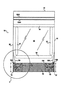
[0015] FIG. IA is a side view of a bag according to our invention in a
flat
configuration.
[0016] FIG. I B is a detailed view of the section A of the bag shown in
FIG. IA.
100171 FIG. 2 is an end view of a bag according to our invention in the
flat
configuration.
[0018] FIG. 3 is a perspective side view of a bag according to our
invention in a stand-
up configuration.
[0019] FIG. 4 is a perspective side view of a bag according to our
invention in the
stand-up configuration.
[0020] FIG. 5 is a side view of a bag according to another embodiment of
our
invention.
[0021] FIGS. 6A to 6G are cross-sectional views of portions of bags
according to
embodiments of our invention.
[0022] FIG. 7 is a side view of a bag according to yet another
embodiment of our
invention.
[0023] FIG. 8 is a side view of a bag according to a still further
embodiment of our
invention.
DETAILED DESCRIPTION OF THE INVENTION
[0024] Our invention relates to a plastic storage bag that includes
features for shifting
the bag between a flat configuration and a stand-up configuration. In the
stand-up
configuration, the bag stands on a substantially flat base without being
grasped by a user
such that the bag can easily be filled.
7
Date Recue/Date Received 2020-06-15
WO 2015/138559
PCT/US2015/019878
[0025] As will be apparent from the description herein, the terms "bag"
and "storage
bag" encompass a broad range of structures designed to contain items. Such bag
structures might also be termed pouches, envelopes, packets, and the like. In
general, the
terms "bag" and "storage bag," as used herein, simply mean a somewhat flexible
container
with an opening, such that the bag is capable of carrying any number of items.
The
storage bags may be tailored for particular uses, for example, the bags may be
used to
store food in a refrigerator in some embodiments, or the bags may be used to
store food in
a freezer in other embodiments.
[0026] Figures IA, 1B, and 2 to 4 are views of a storage bag 100
according to
embodiments of our invention. The bag 100 includes a first sidewall 102 and a
second
sidewall 104 that are connected along side edges 106 and 110 and along a
bottom edge
108. An opening 112 is formed at the top of the bag 100 through which items
may be
placed into the interior of the bag 100. Notably, the bag 100 does not include
a pleat or
gusset at the bottom portion 118 between the first and second sidewalls 102
and 104. That
is, the first and second sidewalls 102 and 104 are directly connected to each
other along
the bottom edge 108 of the bag 100 without any sort of folding or expandable
structure
provided between the sidewalls 102 and 104. The first and second sidewalls 102
and 104
are also directly connected along side edges 106 and 110 without any pleat or
gusset
connecting the two sidewalls 102 and 104.
100271 The opening 112 may be sealed by the interlocking closure
structures 114A,
114B, 116A, and 116B. Interlocking closure structures for plastic storage bags
are well
known in the art, and examples of different shapes and configurations of
interlocking
members that can be used with our storage bag 100 can be seen in U.S. Patent
Nos.
5,070,584; 7,784,160; 7,886,412; 7,946,766; and 8,061,898, and in U.S. Patent
Date Recue/Date Received 2020-06-15
Application Publication No. 2009/0324141. As an alternative to the closure
structures 114A,
114B, 116A, and 116B, in other embodiments, a slider-type closure structure
could be used to
seal the opening 112 of the bag 100 along the top edge of the first and second
sidewalls 102 and
104. Examples of slider-type closure structures can be seen in U.S. Patent
Nos. 5,664,299;
5,836,056; and 7,052,181.
[0028] Illustrative plastic materials that can be used to form the bag 100
include, for example,
polypropylene (PP), polyethylene (PE), metallocene-polyethylene (mPE), low
density
polyethylene (LIDPE), linear low density polyethylene (1.1.,DPE), ultra low
density polyethylene
(ULDPE), biaxially-oriented polyethylene terephthalate (BPET), high density
polyethylene
(1-113PE), polyethylene terephthalate (PET), among other polyolelm plastomers
and combinations
and blends thereof. Still other materials that may be used include styrenic
block copolymers,
polyolefm blends, elastomeric alloys, thermoplastic polyurethanes,
thermoplastic copolyesters,
thermoplastic polyamides, polymers and copolymers of polyvinyl chloride (PVC),
polyvinylidene chloride (PVDC), saran polymers. ethylene/vinyl acetate
copolymers, cellulose
acetates, polyethylene terephthalate (PET), ionomer, polystyrene,
polycarbonates, styrene
aeryloacrylonitrile, aromatic polyesters, linear polyesters, and thermoplastic
polyvinyl alcohols.
Those skilled in the art will recognize that a wide variety of other materials
may also be used to
form the storage bag 100. Those skilled in the art will also recognize that by
using the plastic
materials described above, the storage bag 100 can be made in a range of
colors and
transparencies.
9
Date Recue/Date Received 2020-06-15
WO 2015/138559
PCT/US2015/019878
100291 A variety of manufacturing techniques may be used to form the
plastic storage
bag 100. As one specific example, the sidewalls 102 and 104 of the bag 100 can
be
extruded together as one sheet, with a portion of the first sidewall 102 and a
portion of the
second sidewall 104 being joined together to form the bag structure using, for
example,
thermoplastic welding techniques. As another example, the first and second
sidewalls 102
and 104 can be formed as separate structures that arc joined together along
the three edges
106, 108, and 110. Along these lines, when referring herein to the sidewalls
102 and 104
as being "connected" together, the sidewalls may be integrally formed, or,
alternatively,
the sidewalls 102 and 104 may be separate structures that have been joined
together at the
connection. The formation of specific additional features of the bag 100 will
be described
below.
100301 The storage bag 100 according to our invention can be shifted
between a flat
configuration, as shown in Figures 1A, I B, and 2, and a stand-up
configuration, as shown
in Figures 3 and 4. The bag 100 maintains the stand-up position even though it
does not
include a pleat or gusset adjacent to its bottom edge 126. Instead, the bag
100 is made to
stand upright through unique configurations at the bottom portions 118 of the
sidewalls
102 and 104, which will now be described.
[0031] As shown in Figures lA and 3, a plurality of shift regions 122A,
122B, 123A,
123B, 124A, 124B, 124C, 124D, 126, and 128 is formed in the bottom portion 118
of the
first sidewall 102. Figure 1B shows the details of the region A in Figure 1A,
including the
additional shift regions 125A, 125B, and 125C. The shift regions are
configured to allow
the bag to be easily shifted between flat and stand-up configurations, as will
be described
in detail below. In some embodiments, the shift regions 122A, 122B, 123A,
123B, 124A,
124B, 124C, 124D, 125A, 125B, 125C, 126, and 128 are slight indentations,
scores, or
Date Recue/Date Received 2020-06-15
WO 2015/138559
PCT/US2015/019878
crimps formed in the sidewalls 102 and 104 of the bag 100 that are made to a
depth such
that the bag 100 can easily shift about the regions. However, the shift
regions 122A,
122B, 123A, 123B, 124A, 124B, 124C, 124D, 125A, 125B, 125C, 126, and 128 are
not
made to a depth that substantially weakens the integrity of the bag 100. Those
skilled in
the art will recognize that a variety of techniques can be used to form the
shift regions
122A, 122B, 123A, 123B, 124A, 124B, 124C, 124D, 125A, 125B, 125C, 126, and
128,
such as deforming the bag 100 with a mechanical structure or, as another
example, by
using ultrasonic deforming. As yet another example, the shift regions 122A,
122B, 123A,
123B, 124A, 124B, 124C, 124D, 125A, 125B, 125C, 126, and 128 can be formed by
deforming the sidewalls 102 and 104 of the storage bag 100 by squeezing
portions of the
sidewalls 102 and 104 so as to permanently deform the portions in the shapes
of the shift
regions.
[0032] With the shift regions 122A, 122B, 123A, 123B, 124A, 124B, 124C,
124D,
125A, 125B, 125C, 126, and 128, the bag 100 is shiftable between a flat
configuration, as
shown in Figures 1A, 1B, and 2, and a stand-up configuration, as shown in
Figures 3 and
4. In the flat configuration, the first and second sidewalls 102 and 104 are
positioned
adjacent to each other. In the stand-up configuration, the first and second
sidewalls 102
and 104 are separated from each other. To separate the first and second
sidewalls 102 and
104, the bottom portion 118 of the bag is moved about the shift regions 122A,
122B,
123A, 123B, 124A, 124B, 124C, 124D, 125A, 125B, 125C, 126, and 128 such that
the
bottom portion 118 forms a substantially flat base for the upright bag 100. By
being
shifted in this manner, the ends of the bottom portion 118 that are adjacent
to the corners
120 and 121 extend outward in a triangular-shaped configuration. The bottom
portion 118
of the bag 100 is thereby outlined by the shift regions 124A, 124B, 124C,
124D, 126, and
11
Date Recue/Date Received 2020-06-15
WO 2015/138559
PCTALJS2015/019878
128. When shifting from the flat configuration to the stand-up configuration,
the bag 100
is also moved about shift regions 122A and 122B, such that the portions 130A
and 130B
of the first sidewall 102 are shifted over other portions 128A and 128B of the
first
sidewall 102. Shifting to the stand-up configuration is facilitated by
grasping the bag 100
at the portions 130A and 130B, which, in effect, act as hinges that naturally
effect shifting
of the bag 100 to the stand-up configuration.
100331 In the
embodiment shown in Figures lA to 4, the shift regions are provided on
both of the bottom corners of both sidewalls 102 and 104 of the bag 100.
Specifically, a
plurality of shift regions 124C, 124D, and 128 is provided on the second
sidewall 104
corresponding to the shift regions 124A, 124B, and 126 that are provided on
the first
sidewall 104, as can be seen in Figures 3 and 4. Note that by "corresponding,"
we mean
that the shift regions are in the same relative positions on the first and
second sidewalls
102 and 104. In other embodiments, however, fewer shift regions may be
provided. For
example, the shift regions may only be provided in one comer of one of the
sidewalls 102
and 104. In still other embodiments, shift regions may be provided on the two
bottom
corners of one of the sidewalls 102 and 104, but not provided on the other of
the sidewalls
102 and 104. In yet other embodiments, the shift regions may be provided on
the bottom
comer of one of the sidewalls 102 and 104 and other shift regions may be
provided on the
bottom comer on the other side of the other sidewall 102 or 104, such that the
shift regions
on one side of the bag 100 do not correspond to shift regions on the other
side of the bag
100.
100341
Similarly, the bag 100 may only include some, but not all, of the depicted
shift
regions 122A, 122B, 123A, 123B, 124A, 124B, 124C, 124D, 125A, 125B, 125C, 126,
and
128. For example, in one embodiment, the bag 100 might include the shift
regions 122A,
12
Date Recue/Date Received 2020-06-15
WO 2015/138559
PCT/US2015/019878
122B, 124A, and 124B, but not include any of the other depicted shift regions
123A,
123B, 124C, 124D, 125A, 125B, 125C, 126, and 128. In such an embodiment, the
shift
regions 122A, 122B, 124A, and 124B facilitate shifting of the bag 100 from the
flat
configuration to the stand-up configuration. Also, in the depicted
embodiments, the shift
regions 122A, 122B, 123A, 123B, 124A, 124B, 124C, 124D, 125A, 125B, 125C, 126,
and
128 arc shown to extend in continuous lines. In other embodiments, however,
the shift
regions 122A, 122B, 123A, 123B, 124A, 124B, 124C, 124D, 125A, 125B, 125C, 126,
and
128 can be discontinuous. For example, any one of the shift regions can be
formed as a
plurality of distinct line segments, dots, etc. As will be appreciated by
those skilled in the
art, the number and continuity of the shift regions provided to a bag
according to our
invention can be adjusted in order to make the shifting of the bag more or
less easy, or the
number and continuity of the shift regions can be adjusted based on other
factors such as
aesthetics and cost of manufacturing of the bag. Along these lines, in some
embodiments,
the bag may only be provided with one of the shift regions 122A, 122B, 123A,
123B,
124A, 124B, 124C, 124D, 125A, 125B, 125C, 126, and 128.
100351 As can
be seen in Figures IA and 1B, there are two angles a and 0 formed by
the shift regions 122A, 122B, 124A, 124B, 124C, 124D, 126, and 128 relative to
the side
edge 106, side edge 110, and bottom edge 108. Further, with the reference
lines 134A and
134B, areas 128A, 128B, 132A, and 132B are defined. Note that reference lines
134A
and 134B are provided in Figures IA and 1B for purposes of understanding our
invention,
but are not actually a structure in the bag 100. As is apparent from the
figures, the size of
angles a and 0 determines the relative sizes of the areas 128A, 128B, 132A,
and 132B.
Generally speaking, we have found that, to facilitate the shifting movement
from the flat
configuration to the stand-up configuration, the areas 128A and 128B should be
13
Date Recue/Date Received 2020-06-15
WO 2015/138559
PCT/US2015/019878
approximately equal to the areas 132A and 132B. Further, we have found that
shifting is
greatly facilitated when the angles a and p satisfy the following Equation
(1):
fl.--a+45 (1)
7
When angles a and p are generally defined by the relation of Equation (1), the
bag 100
can be easily shifted from the flat configuration to the stand-up
configuration. Note,
however, that Equation (1) does not have to be exactly satisfied, but rather,
both a and p
can vary slightly from the relation while still allowing for the bag 100 to be
easily moved
from the flat configuration to the stand-up configuration. For example, given
a specific
angle a, then angle 13 may vary by less than about 2 degrees from the value
for angle 13
calculated from Equation (1). Given a specific angle 13, then angle a may vary
less than
about 4 degrees from the value for angle a calculated from Equation (1). For
example,
in specific embodiments, angle a is about 14 degrees to about 16 degrees and
angle 13 is
about 37 degrees to about 39 degrees. It should again be noted, however, that
the bag 100
is not necessarily limited to any particular angle a and angle (3.
[0036] The horizontal shift regions 126 and 128 extend a height H above
the bottom
edge 108 of the bag 100. This height H will, in effect, determine the width of
the flat base
of the bag 100 when the bag 100 is in the stand-up configuration. That is, as
shown in
Figure 4, the width of the bottom of the bag 100 is about 2H at a center
region of the bag.
In embodiments of our invention, the height H is about 1 inch to about 3.5
inches, more
specifically, about 1.5 inches to about 3 inches, and still more specifically,
about 2 inches
to about 2.5 inches. It follows that the width of the base of the bag is about
twice these
heights, i.e., about 2 inches to about 7 inches, more particularly, about 3
inches to about 6
inches, and still more particularly, about 4 inches to about 5 inches. In a
specific
embodiment, the height H is about 2 inches, and, thus, the width of the base
of the bag is
14
Date Recue/Date Received 2020-06-15
WO 2015/138559
PCT/US2015/019878
about 4 inches. Generally speaking, with such ranges, storage bags of standard
sizes, such
as those for storing food, can be made to stand upright.
[0037] With the configuration of the bag 100 shown in Figures IA to 4,
the bag 100
may be made to stand upright without any additional structural features. For
example,
unlike other bags known in the art, the bag 100 does not need to include a
pleat or gusset
between the bottom portions of the first and second sidcwalls 102 and 104. In
addition, to
not requiring a pleat or gusset, the sidewalls 102 and 104 of the bag 100 can
be made with
a relatively uniform thickness. Along these lines, in some embodiments, the
sidewalls 102
and 104 may have a thickness of only about 1.6 mils to about 2.6 mils. As one
of ordinary
skill in the art will appreciate, a thickness of about 1.6 mils is
substantially thinner than
the thickness of many types of stand-up plastic storage bags.
[0038] While the bag 100 will remain in the stand-up configuration when
provided
with uniformly slightly thick sidewalls 102 and 104, in other embodiments,
specific
portions of the bag 100 are made slightly thicker in order to further
facilitate the stand-up
configuration. In one example, regions of the bottom portions 108 of the
sidewalls 102
and 104 of the bag 100 are made thicker than the rest of the bag 100.
Specifically, the
bottom portions 108 are about twice as thick as the other portions of the
sidewalls 102 and
104. In other embodiments, regions of the bottom portions 108 are made about
one mil
thicker than the other portions of the sidewalls 102 and 104. When an
extruding technique
is used to manufacture the bag 100, the bottom portions 108 can be made
thicker by
adjusting the amount of material used to form the bottom portions 108 in
comparison with
the other portions, e.g., by adjusting the extruding process such that the
bottom portions
108 are about 1 mil thicker, while the other portions of the side walls 102
and 104 are
reduced by about 0.1 mil of thickness.
Date Recue/Date Received 2020-06-15
WO 2015/138559
PCT/US2015/019878
[0039] In some embodiments, the bottom portions 108 of the first and
second
sidewalls 102 and 104 can be made visually distinct from the other portions of
the first
and second sidewalls 102 and 104. For example, a visually distinct texture
could be
formed in the bottom portions 108 between the horizontal shift regions 126 and
128 of the
first and second sidcwalls 102 and 104. Such a texture may aid the user in
identifying the
bottom portions 108 that are to be shifted. Further, the texture may increase
the friction of
the base when the bag 100 is in the stand-up configuration, thereby further
stabilizing the
bag 100.
100401 In order to further facilitate the stand-up configuration of the
bag 100, other
portions of the sidewalls 102 and 104 above the bottom portions 108 can be
made stiffer.
Examples of such stiffer portions are the areas labeled as 140, 142, 144, and
146 on the
first sidewall 102 in Figure 1A. Although not shown, corresponding stiffer
areas can be
formed on the second sidewall 104. The stiffer portions 140, 142, 144, and 146
provide
structural support to the sidewalls 102 and 104 that helps to maintain the bag
upright in
the stand-up configuration. While the stiffer areas 140, 142, and 146 extend
within the
sidewall 102, the stiffer area 144 extends from the edge 106 to the edge 110
of the
sidewall 102. By extending the full length of the sidewall 102 and being
positioned
adjacent to the opening 112 of the bag 100, the stiffer area 144, along with a
corresponding stiffer area on the second sidewall 104, helps to maintain the
opening 112
in an open position when the bag 100 is in the stand-up configuration and the
closure
structures 114A, 114B, 116A, and 116B are not sealed. At the same time, the
vertical
stiffer areas 140 and 142, and the corresponding stiffer areas on the sidewall
104 help to
push out the sides of the bag in the stand-up configuration. The bag 100,
therefore, can be
maintained in an upright position so that it can be easily filled by a user.
16
Date Recue/Date Received 2020-06-15
WO 2015/138559
PCT/US2015/019878
100411 The stiffer areas 140, 142, 144, and 146 can be formed by
extruding the
sidewalls 102 and 104 of the bag in a manner such that the areas 140, 142,
144, and 146
on the first sidewall 102, and the corresponding portions on the second
sidewall 104, are
made thicker than the other portions of the sidewalls 102 and 104.
Alternatively, the
stiffer areas 140, 142, 144, and 146 can be formed by applying additional
material onto
the sidewalls 102 and 104.
100421 In still other embodiments of our invention, upper portions of
the bag are made
stiffer in order to help maintain the opening 112 in the open position. As
will be
appreciated by those skilled in the art, the lips are the region of the bag
above the closure
structures (L e., the area between the closure structures 116A/B and the top
edge of the bag
shown in Figure 1A). In some embodiments, one or both of the lips of the bag
are made
stiffer, thereby making the opening 112 more readily stay in the open
position.
[00431 Those skilled in the art will recognize many different ways that
the lips of the
bag can be made stiffer. For example, additional material can be added to the
lip areas in
a manner analogous to the way that additional material is added to form the
above-
described areas 140, 142, 144, and 146. That is, the lips can be made stiffer
by providing
additional material in the lip areas such that the lips are thicker than other
portions of the
bag. In this regard, making the lips thicker has an additional benefit of
making the lips
easier to grasp, for example, when the bag is being opened. In a specific
example, the lips
are made 20% stiffer than other portions of the bag, thereby making the bag
opening more
readily stay in the open position and making the lips easier to gasp.
100441 Additional material provided to make the lips stiffer can be the
same material
as the material that is used to form the rest of the bag. Alternatively, a
different material
can be used to stiffen the lips. For example, the bag can be made from PE, and
HDPE can
17
Date Recue/Date Received 2020-06-15
WO 2015/138559
PCT/US2015/019878
be added to the lip areas in order to make the lips stiffer. In other
embodiments, the lips
themselves can be at least partially formed from a different, stiffer material
than other
portions of the bag. For example, when the bag is primarily formed from PE,
the lips can
be separately formed from HDPE, with the higher density HDPE making the lips
stiffer
than the rest of the bag. Of course, the material used to form the lips added
to the lip
areas, or the additional material added to the lips, can be any material that
is compatible
with the other materials used to form the bag.
[00451 As indicated above, the closure structure or closure structures
of a bag are
positioned near the opening. Thus, in addition to, or as an alterative to,
making the lips
stiffer, the closure structure or structures of the bag can be formed from a
material that is
stiffer than other portions of the bag, thereby making the bag more readily
stay in the open
position (when the closure structures are not functioning to close the
opening). In an
embodiment that includes stiffer closure structures, the closure structures
are made from
HDPE, whereas the rest of the bag is made from PE.
[00461 Figure 5 is a side view of a bag 200 according to another
embodiment of our
invention. The bag 200 includes some of the features that are provided in the
embodiments described above, including sidewalls 202 and 204 and closure
structures
224A, 224B, 226A, and 226B. In the bag 200, however, the shift regions 222A,
222B,
224A, and 224B do not extend all the way to corners 220 and 221. Instead, the
shift
regions 222A, 222B, 224A, and 224B extend from positions close to, but not
directly
adjacent to, the comers 220 and 221. In this regard, the shift regions in
embodiments of
our invention may extend from positions "near" the corners, in that the shift
regions
extend from positions directly adjacent to the corners, as shown in the bag
100 in Figure
18
Date Recue/Date Received 2020-06-15
WO 2015/138559
PCT/US2015/019878
1A, or from other positions "near" the corners, in that the shift regions
extend from
positions that are close to the corners, as shown in Figure 5 with respect to
bag 200.
100471 The shift regions 222A, 222B, 224A, and 224B of bag 500 are not
straight, but
instead, have a curved shape. The bag 200 is shiftable between a flat
configuration and a
stand-up configuration by being shifted about the curved shift regions 222A,
222B, 224A,
224B, and 226 in a manner similar to the way that the bag 100 shifts between
configurations, as described above. With the curved shift regions 222B and
224B, the
angle a is measured between the side 210 and a line Ti that is tangent to a
point in the
middle portion of the shift region 222B, and the angle t is measured between
the bottom
208 and a line T2 that is tangent to a point in the middle portion of the
shift region 224B.
Although not shown, similar angles a and 13 can be measured between lines
tangent to the
shift regions 222A, 224A, the side edge 206, and the bottom edge 208. The
angles a and
may be in the relation of Equation (1), as described above.
[00481 In the embodiments described above, a bag according to our
invention is
described as being provided with shift regions that are formed as indentations
in the bags.
In other embodiments, however, the locations about which the bag is shifted
between the
flat and stand-up configurations could be formed in a different manner, such
as by
providing a slight amount of additional polymeric material to the sides of the
bag. For
example, small amount of polyethylene may be provided on the sides of the bag
at the
same positions as the above-described shift regions on the bag. Those skilled
in the art
will appreciate the variety of techniques that could be used to apply such
additional
material, for example, nozzles that turn on and off to rapidly deposit the
material in the
pattern of the shift regions. In other embodiments, the locations about which
the bag can
be shifted are provided as regions of varying thickness, elevation, etc., in
the sides of the
19
Date Recue/Date Received 2020-06-15
WO 2015/138559
PCT/US2015/019878
bag. In this regard, Figures 6A to 6G are cross-sectional views of portions of
bags
according to embodiments of our invention, with the cross sections including
different
shift regions 600A to 600G. Any of the shift regions 600A to 600G may be
provided at
locations about which the bag can be shifted between the flat and stand-up
configurations,
such as the positions of the shift regions in the embodiments described above.
Thus, the
shift regions 600A to 600G provide for a bottom when the bag is in a stand-up
configuration, and the bag need not include a pleat or gusset formed between
the sidewalls
at the bottom of the bag.
100491 Figure 7 shows a specific example of how a shift region, as
generally depicted
in Figure 6B, can be used in a bag according to our invention. The bag 700
includes shift
regions 727A, 727B, 724A, 724B, 726, and 728 (the region 728 being provided on
the
sidewall 704 that is opposite from the shown sidewall 702). In this
embodiment, the shift
regions 726 and 728 have a bead-like configuration. Note that the beaded shift
regions
726 and 728 correspond in their positions to the shift regions 126 and 128 of
the bag 100
shown above. As such, the shift regions form the edges of the base of the bag
700 when
the bag is shifted to the stand-up configuration.
[0050] The beaded shaped shift regions 726 and 728 can be formed from
the same
material as that of the bag, for example, by specifically extruding the
material that forms
the sidewalls 702 and 704 such that the shift regions 726 and 728 are formed
with the
beaded shape. Alternatively, the beaded shift regions 726 and 728 can be
formed by using
a different material to form the sidewalls of the bag, with the different
material being used
to form the shift regions 726 and 728 at the same time as the sidewalls 702
and 704 are
formed, or by adding the different material to form the shift regions 726 and
728 after the
sidewalls 702 and 704 are formed. In this regard, the shift regions 726 and
728 can be
Date Recue/Date Received 2020-06-15
WO 2015/138559
PCIYUS2015/019878
formed from any of the plastic materials we discussed above. As other
examples, the
material used to form the beaded shift regions 726 and 728 could be an
adhesive, an ink,
or a wax material. In some cases, the additional material used to form the
beaded shift
regions 726 and 728 is not directly attached to the sidewalls 702 and 704 of
the bag, but
rather one or more intermediate layers are formed between the beaded shift
regions 726
and 728 and the sidewalls 702 and 704. In still other embodiments, the beaded
regions
726 and 728 themselves are formed from multiple layers of one or more
materials.
[0051] The
beaded shift regions 726 and 728 can be formed to any thickness such that
the regions facilitate shifting of the bag, as described above. In some
embodiments,
however, the beaded shift regions 726 and 728 are about two to about twenty
times thicker
than the sidewalls 702 and 704 of the bag. In still more specific embodiments,
the beaded
shift regions 726 and 728 are about 2 to about ten times thicker than the
sidewalls 702 and
704 of the bag. And, in a specific embodiment, the beaded shift regions 726
and 728
extend about 15 mils from the surface of the sidewalls 702 and 704.
[0052] It
should be noted that while the beaded shift regions 726 and 728 are depicted
on the outside surfaces of the sidewalls 702 and 704, as is the case with all
of the shift
regions described herein, one or both of the beaded shift regions 726 and 728
could be
provided on the inside surfaces of the sidewalls 702 and 704 (i.e., in the
interior of the
bag). It should also be noted that while the beaded shift regions 726 and 728
have a
generally rounded shape as shown in Figure 6B, the beaded shift regions 726
and 728 may
be more or less rounded than depicted. In fact, the beaded shift regions 726
and 728 need
not be rounded, but rather may be formed in any shape, e.g., square,
rectangular, or
triangular.
21
Date Recue/Date Received 2020-06-15
WO 2015/138559
PCT/1152015/019878
[0053] In the embodiment depicted in Figure 7, the beaded shift region
726 on
sidewall 702 is slightly offset from the corresponding beaded shift region 728
on sidewall
704 such that the beaded shift regions 726 and 728 are not positioned
immediately
adjacent to each other when the bag 700 is in the flat configuration. This
offset is not
required, but the offset may minimize the formation of leaks wherein the shift
regions 726
and 728 meet the sides 106 and 110 of the bag. Of course, as generally
described above,
in some embodiments, the beaded shift regions 726 and 728 do not extend to the
sides 106
and 110, but rather only extend over a part of the length of the sidewalls 702
and 704 of
the bag. Further, as also generally described above, the beaded shift regions
726 and 728
may be continuous or discontinuous.
[0054] A still further embodiment of the invention is shown in Figure 8.
This
embodiment includes additional shift regions in the lower and upper portions
of the
sidewalls 802 and 804 of the bag 800. With respect to the bottom portion, a
pattern of
seven shift regions 822A, 824A, 826A, 828A, 830A, 832A, and 834A is provided
near
one of the bottom corners of sidewall 802, and a similar pattern of seven
shift regions
822B, 824B, 826B, 828B, 830B, 832B, and 834B is provided at the other corner
of
sidewall 802. These shift regions 822A, 824A, 826A, 828A, 830A, 832A, 834A,
822B,
824B, 826B, 828B, 830B, 832B, and 8348 can take any of the forms described
above,
e.g., indentations, scores, beads, etc. Notably, the pattern of these shift
regions is such that
some of the shift regions cross one or more of the other shift regions. For
example, shift
region 828A crosses shift region 830A and shift region 832A. As another
example, shift
region 824A crosses shift regions 826A, 828A, and 830A. We have found that
such a
pattern, with at least one shift region crossing another shift region,
facilitates the shifting
function, thereby making it easier to move the bag between the flat and stand-
up
22
Date Recue/Date Received 2020-06-15
WO 2015/138559
PCT/US2015/019878
configurations. And, having multiple shift regions cross more than one shift
region still
further enhances the shifting functionality. Note that, although not shown in
Figure 8, a
similar pattern of shift regions can be formed at the bottom two comers of the
opposite
sidewall 804 of the bag 800. Further, any combination of such shift regions
can be formed
at the corners of the bag, e.g., the shift regions are only provided at one
corner on sidewall
802 and one corner of the sidewall 804. Also, the pattern shown may be altered
such that
one or more of the shift regions is omitted, or one or more additional shift
regions are
provided.
[00551 With
respect to the upper portion of bag 800, shift regions 836A and 838A are
provided on sidewall 802 below the closure structures 814A/B and 816A1B, with
the shift
regions 836A and 836B extending from the side 806 of the bag 800. Similarly,
shift
regions 836B and 838B are provided extending from the side 810. The additional
shift
regions 836A, 836B, 838A, and 838B help to maintain the opening 812 of the bag
in the
open position by causing portions of the bag 800 to deflect along the shift
regions 836A,
836B, 838A, and 838B when the bag 800 is opened. These shift regions 836A,
836B,
838A, and 838B can take any of the shift region forms described above, e.g.,
indentations,
scores, beads, etc. And, the shift regions 836A, 836B, 838A, and 838B can be
provided
anywhere in the general area of the upper portion near sides 806 and 808. In a
specific
embodiment, however, the shift regions 836A and 836B are about one inch below
the
closure structures 814A/B, as measured along sides 806 and 810, and the shift
regions
838A and 838B are about one-half inch below the shift regions 836A and 836B
(about one
and one-half inches below the closure structures 814A/B), as measured along
sides 806
and 810. In the specific embodiment, the shift regions 836A, 836B, 838A, and
838B
23
Date Recue/Date Received 2020-06-15
WO 2015/138559
PCT/U52015/019878
extend about one inch along sidewall 802, as measured in a line perpendicular
from sides
806 and 810.
100561 In some embodiments, shift regions corresponding to shift regions
836A,
836B, 838A, and 838B are provided on the second sidewall 804 of the bag 800.
Those
skilled in the art will recognize that more or less shift regions can be
provided in a similar
manner to the 836A, 836B, 838A, and 838B on either of the upper portions of
the
sidewalls 802 and 804.
[00571 Any of the shift regions provided on the bag 800 can be combined
with any of
the other embodiments of our bag as described herein. For example, the shift
regions
836A, 836B, 838A, and 838B could be provided on the bags 100 and 200 described
above. Further, features from the other embodiments described herein can also
be
provided with bag 800. For example, the visually distinct texture described
above can be
provided on the bottom portion of bag 800, if desired. More generally, as will
be fully
appreciated by those skilled in the art, any of the features described herein
with respect to
a specific embodiment may be combined with, or substituted for, features of
another
specific embodiment. For example, a bag according to our invention could be
formed
with the combination of (1) the stiffer portions 140, 142, 144, and 146, as
described in
conjunction with the bag 100, (2) the curved shift regions 222A, 222B, 224A,
and 224B,
as described in conjunction with the bag 200, (3) the beaded shift region, as
described in
conjunction with the bag 700, and (4) the shift regions 836A, 836B, 838A, and
838B, as
described in conjunction with the bag 800.
[00581 A bag according to our invention is highly functional inasmuch as
it can be
made to stand upright without being held by a user. The bag can thereby be set
on a
surface, and easily filled by the user. This stand-up configuration is
achieved without the
24
Date Recue/Date Received 2020-06-15
WO 2015/138559
PCT/US2015/019878
use of a pleat, gusset, or other additional structure at the bottom portion of
the bag. Thus,
the bag can be made to lay substantially flat when not in use, and thereby be
compactly
stored. Further, by not including an additional structure at the bottom
portion, the bag can
be made from substantially less material than other stand-up bags known in the
art. Those
skilled in the art will recognize numerous other advantageous of our bag based
on the
foregoing description.
100591 Although this invention has been described in certain specific
exemplary
embodiments, many additional modifications and variations would be apparent to
those
skilled in the art in light of this disclosure. It is, therefore, to be
understood that this
invention may be practiced otherwise than as specifically described. Thus, the
exemplary
embodiments of the invention should be considered in all respects to be
illustrative and
not restrictive, and the scope of the invention to be determined by any claims
supportable
by this application and the equivalents thereof, rather than by the foregoing
description.
Industrial Applicability
[0060] The invention described herein can be used in the commercial
production of
storage bags. Such storage bags have a wide variety of uses, such as being
utilized to
store food, chemicals, or other substances.
Date Recue/Date Received 2020-06-15