Note: Descriptions are shown in the official language in which they were submitted.
CA 03084241 2020-06-02
WO 2019/110451 1
PCT/EP2018/083220
An apparatus for separating particles of different sizes by means of cyclonic
separation
Technical field
The present invention relates to an apparatus for separating smaller particles
from larger
particles by means of cyclonic separation. The invention also relates to use
of such an
apparatus for separating wood particles from a wood powder.
Background
In many applications it is necessary to separate particles of different sizes
or density. An air
classifier is an apparatus that separates materials with different sizes and
density. It works by
injecting a stream of material to be sorted into a separation chamber which
contains a vertical
column of rising air. Inside the separation chamber, the air drag on the
material supplies an
upward force which counteracts the force of gravity and lifts the material to
be sorted up into
the air. Due to the dependence of air drag on size and shape of an object, the
particles in the
moving air column are sorted vertically and can be separated in this manner.
Air classifiers are
commonly employed in industrial processes where a large volume of mixed
materials with
differing physical characteristics need to be separated quickly and
efficiently.
Cyclonic separation is a method of removing particles from air, gas or liquid
streams, without
the use of filters, through vortex separation. Rotational effects and gravity
are used to
separate mixtures of solids and air. A high-speed rotating air flow is
established within a
cylindrical or conical container called a cyclone. The air flows in a helical
pattern. Larger
particles in the rotating stream have too much inertia to follow the tight
curve of the stream,
and strike the outside wall, then fall to the bottom of the cyclone where they
can be removed.
The rotating air flow moves towards a narrow end of the cyclone thus
separating smaller and
smaller particles. The cyclone geometry, together with volumetric flow rate,
defines the cut-
off point for the particle size of the cyclone. This defines the size of
particles that will be
removed from the stream with at least 50% efficiency. Particles larger than
the cut-off point
will be removed with a greater efficiency, and smaller particles with a lower
efficiency.
There is as desire to use wood powder as a replacement of fossil fuel. The
size of the particles
of the wood powder is essential for the use of the wood powder as fuel. Thus,
there is a desire
to provide an apparatus that makes it possible to separate larger wood
particles from smaller
to achieve wood powder including particles of desired sizes. A problem with
separating wood
particles from wood powder is that wood material becomes lumped when it is
moist, which
makes it difficult to separate the particles. Thus, an efficient separation is
needed.
US7108138 discloses a material classifier that includes a cyclone comprising a
cyclone inlet, a
cyclone outlet, a blower and a blower discharge; an air diffuser connected at
a diffuser inlet
to the cyclone outlet and at a diffuser outlet to an air lock such that the
cyclone and air diffuser
are in fluid communication; wherein the diffuser including a central
cylindrical portion
including an air inlet for admitting controlled amounts of diffuser air around
substantially the
CA 03084241 2020-06-02
WO 2019/110451 2
PCT/EP2018/083220
entire cylinder outer periphery of the central cylindrical portion, wherein
the material
classifier separating fine particles from coarse particles and discharging the
fine particles
together with air out the blower discharge, and discharging the coarse
particles through the
air lock, such that varying the amount of diffuser air one can control the
size of the fine
.. particles being separated from the coarse particles.
US4526678 discloses an apparatus for separating large from small particles
suspended in a
moving stream of gas by centrifugal forces which includes sifting of large
particles in a stream
of gas to strip small particles away from the larger particles.
DE433256 discloses an apparatus for separating large particles from small
particles, wherein
.. the apparatus comprises a separation chamber, an air inlet, an outlet and a
feeding pipe. The
material is disposed in the separation chamber by means of the feeding pipe.
By means of an
air flow created by the air inlet unit the lighter material is elevated in the
separation chamber
and is then fed through the outlet unit. The heavier material falls down to a
separate outlet.
The apparatus does not use cyclonic separation.
.. CH314655 discloses an apparatus for separating large particles from small
particles, wherein
the apparatus comprises a separation chamber, an outlet, and air inlet, a
feeding pipe. The
material is supplied to the separation chamber through the feeding pipe and
then falls on a
displacement body causing the material to be evenly distributed. The air
coming from the air
inlet then causes the lighter material to be elevated to the outlet. This
apparatus does not use
.. cyclonic separation.
A problem with the prior art apparatus is that they do not provide efficient
separation of
material including lumps, such as moist wood material. For example, the shape
of the
separation chamber does not now allow for a constant air flow, resulting in
less efficient
separation. Further, the arrangement and design of the feeding pipe may cause
the material
.. to become stuck in the feeding pipe.
Summary
An aspect of the present invention is to provide an improved apparatus for
separating smaller
particles from larger particles in a material containing particles of
different sizes. More
specifically, the disclosure provides for an apparatus that enables efficient
separation of moist
.. material containing lumps. Yet another aspect of the disclosure is to
provide an apparatus
achieving efficient separation of wood particles.
This aspect is achieved by an apparatus as defined in claim 1.
The apparatus comprises a feeding pipe having an upper end for receiving
material to be
separated and defining a first channel for transporting the material to a
lower end of the
.. feeding pipe, a separation chamber having a curved wall, a first opening
arranged at an upper
CA 03084241 2020-06-02
WO 2019/110451 3
PCT/EP2018/083220
end of the separation chamber, a second opening arranged at a lower end of the
separation
chamber, and the separation chamber surrounds the feeding pipe such that a
second channel
is formed between the feeding pipe and the curved wall. The feeding pipe and
the separation
chamber are concentrically arranged. The apparatus comprises an air inlet unit
arranged for
supplying air to the second opening of the second channel, and an outlet unit
arranged for
receiving air and separated material from the first opening of the second
channel and to
discharge the air and separated material. The curved wall is conically shaped
and tapers from
the second opening to the first opening of the separation chamber, and the
feeding pipe and
the separation chamber are concentrically arranged.
The rotating air flow is flowing upwards from the lower end of the second
channel to the upper
end of the second channel. The material is separated by means of the rotating
air flow since
larger particles are moved downwards due to gravity and smaller particles
follow the rotating
air flow. Larger particles that follow the rotating air flow will strike the
wall of the separation
chamber, and then fall downwards due to gravity. Thus, the smallest particles
remain in the
air flow the longest and travel the highest in the second channel.
Due to the fact that the curved wall of the separation chamber is conically
shaped and tapers
from the second opening to the first opening of the separation chamber, the
curved wall
continually decreases from the air inlet to the air outlet of the separation
chamber. The
steepness of the curved wall prevents heavier particles from moving to the
upper end of the
separation chamber and allows lighter particles to move to the upper end of
the second
channel. The conical shape of the curved wall allows for a constant air flow
without
disturbances. The separation is further improved by having the feeding pipe
and the
separation chamber concentrically arranged. This along with the conical shape
of the curved
wall creates a uniform airflow towards the upper end, preventing the air flow
to vary, resulting
in an efficient separation of the particles.
Since the curved wall is conically shaped, the radius of separation chamber
continuously
decreases from the second opening of the separation chamber, where the air is
inlet, to the
first opening of the separation chamber, where the air is outlet. Thus, also
the second channel
is conically shaped and continuously decreases towards the upper end of the
separation
chamber. A further advantage with the conical shape is that it makes it easier
to extract
smaller particles since it provides an increasing upward force as the radius
of the second
channel decreases towards the upper end.
The material is fed to the separation chamber from above through the feeding
pipe. The
feeding pipe has a longitudinal axis extending between the upper and lower end
of the feeding
pipe. The feeding pipe and the separation chamber are concentrically arranged,
which means
that the longitudinal axis of the feeding pipe is aligned with an axis of
symmetry of the
separation chamber. Thus, the feeding pipe can be vertically arranged when the
apparatus is
CA 03084241 2020-06-02
WO 2019/110451 4
PCT/EP2018/083220
in use, and the material supplied to the upper end of the feeding pipe will
fall down into the
separation chamber due to gravity. Accordingly, the supplied material is
prevented from
sticking to the walls of the feeding pipe. This is particularly advantageous
when the supplied
material is moist, such as wood material.
The second channel surrounds the feeding pipe and accordingly surrounds the
first channel.
The first and second channels are arranged coaxial. Preferably, the separation
chamber has a
larger inner diameter than the outer diameter of the feeding pipe to be able
to receive the
feeding pipe and to surround the feeding pipe. The second channel is formed
between the
feeding pipe and the separation chamber. Since the wall of the separation
chamber is curved,
it encourages the air flow to rotate in the second channel.
In one aspect, the separation chamber is shaped as a truncated cone having one
opening in
the narrow end and another opening is in the wider end of the truncated cone.
In one aspect,
the second opening is said opening is in the wider end of the truncated cone.
In one aspect, the feeding pipe penetrates through the opening in the narrow
end of the
separation chamber, so that said first opening is formed between the curved
wall of the
separation chamber and the feeding pipe to allow the rotating air flow and
separated particle
in the separation chamber to leave the separation chamber.
In one aspect, the first opening is annular and surrounds the feeding pipe.
In one aspect, the second opening is circular. Suitably, the second opening
has a diameter
corresponding to an inner diameter of the lower end of the separation chamber.
In one aspect, the air inlet unit comprises a housing defining a curved third
channel for the air
flow having an inlet opening for receiving the air and the third channel is
arranged in
communication with a lower end of the second channel to allow the air flow in
the curved
third channel to enter the lower end of the second channel.
In one aspect, the outlet unit comprises a housing defining a curved fourth
channel for the air
flow having an outlet opening for discharging the air and separated material,
and the fourth
channel is arranged in communication with the upper end of the second channel
to allow the
air flow in the second channel to enter the fourth channel.
The apparatus comprises a suction unit operatively connected to the outlet
opening of the
outlet unit and arranged for sucking air from said inlet opening to said
outlet opening via said
second, third and fourth channels so that a rotating air flow is formed in
said second channel
and smaller particles are transported upwards to the outlet unit by means of
the rotating air
flow while larger particles are moved downwards due to gravity. The suction
unit sucks air
from the fourth channel and by that generates a rotating air flow in the
fourth channel. Since
the fourth channel is curved, it encourages the air flow to rotate. The
suction unit also sucks
CA 03084241 2020-06-02
WO 2019/110451 5
PCT/EP2018/083220
air from the second channel via the fourth channel and by that a rotating air
flow is generated
in the second channel. The curved third channel supplies air to the second
opening of the
separation chamber, where the rotating air flow in the second channel is
started. Since the
third channel is curved, it encourages the air flow to rotate. The fourth
channel receives the
.. rotating air flow including separated material and air from the second
channel and guides the
air flow to the outlet opening of the outlet unit where the separated
particles can be collected.
Due to the curved form of the fourth channel, the speed of the rotating air
flow is essentially
maintained when the air flow enters the outlet unit. Thus, the high speed of
the rotating air
flow is maintained. The combination of the third and fourth curved channels
achieves a high-
speed rotating air flow in the separation channel. The high-speed rotating air
flow in
combination with the conical shape of the curved wall of the separation
chamber achieves a
very efficient separation of particles, for example, of wood particles.
Another advantage with
the apparatus is that it enables separation of large volumes of material in
relation to its own
size.
The apparatus separates smaller particles from larger particles by means of
cyclonic
separation, which has been proven to be very efficient for separating
particles such as wood
particles. Due to the fact that the rotating air flow is formed in the second
channel defined
between the feeding pipe and the wall of the separation channel, the length of
the part of the
feeding pipe that protrudes into the separation chamber together with the flow
rate of the
rotating air flow define the cut point of the cyclone, and accordingly define
a set maximum
size of the particles that will be separated from the material. By reducing
the length of the
part of the feeding pipe that protrudes into the separation chamber, the
length of the second
channel is reduced and accordingly the size of the particles that reach the
outlet unit is
increased, i.e. the set maximum size of the separated particles is increased.
By increasing the
length of the part of the feeding pipe protruding into the separation chamber,
the length of
the second channel increase and accordingly the size of the particles that
reach the outlet unit
is decreased, i.e. the set maximum size of the separated particles is
decreased. Thus, by
varying the length of the part of the feeding pipe that protrudes into the
separation chamber
it is possible to provide a coarse adjustment of the size of the particles to
be separated.
The invention enables dividing material containing particles of different
sizes into a first
fraction of particles having a smaller size and a second fraction of particles
having a larger size.
The invention makes it easy to control and change the cut-off point for the
particle size of the
cyclone, and accordingly the size of the particles in the separated fractions.
This is
advantageous since different applications require different sizes of the
separated particles.
For example, the invention is useful for separating wood power into two
fractions of particles,
one smaller and one larger than a set size.
The sentence "a suction unit operatively connected to the outlet opening"
means that the
outlet opening can be directly or indirectly connected to the suction unit.
However, the
CA 03084241 2020-06-02
WO 2019/110451 6
PCT/EP2018/083220
connection between the outlet opening and the suction unit should preferably
be airtight to
achieve a depression at the outlet unit. The upper end of the second channel
is in
communication with the fourth channel.
A further advantage is that the apparatus does not have any motors inside the
separation
chamber or in close vicinity of the separation chamber. Instead, the apparatus
has a suction
unit connected to the outlet unit arranged to generate the rotating air flow
in the second
channel by sucking air from the air inlet unit to the outlet unit. This is
advantageous since it
reduces the risk of setting the material inside the separation chamber on fire
due to sparks
from the motor. This is particularly important when handling inflammable
materials, such as,
wood powder.
The suction unit is a unit, for example, an air exhauster or a fan, which
generates depression
at the outlet unit. Due to the pressure differential between the inlet and
outlet units a rotating
air flow is generated from the inlet unit, through the second channel to the
outlet unit. The
rotating flow brings particles from the lower end of the feeding pipe to the
outlet unit. The
particles follow the air flow and are transported to the outlet unit by means
of the air flow.
The outlet unit can be directly or indirectly connected to the suction unit.
In one aspect, the curved fourth channel surrounds the feeding pipe. Suitably,
the curved
fourth channel surrounds an upper part of the feeding pipe.
In one aspect, the curved third channel surrounds the separation chamber.
Suitably, the
curved third channel surrounds a lower part of the separation chamber.
In one aspect, the first opening is annular and surrounds the feeding pipe.
The curved fourth
channel is arranged in communication with the second channel via the annular
first opening
of the separation chamber. Due to the fact that the first opening is annular
it allows the
rotating air flow to enter the fourth channel from the second channel from all
directions.
Accordingly, the air can be sucked from the separation chamber into the outlet
unit all the
way around the feeding pipe and by that the separated particles are prevented
from falling
downwards to the bottom of the separation chamber.
In one aspect, the housing of the outlet unit is attached to the upper end of
the separation
chamber and the housing of outlet unit surrounds the annular first opening of
the separation
chamber. Thus, the annular first opening is formed between the second channel
and the
fourth channel to allow the rotating air flow in the second channel to enter
the fourth channel.
In one aspect, the air inlet unit comprises a third opening arranged in
communication with the
second opening of the separation chamber to allow the rotating air flow in the
curved third
channel to enter the second channel, and said third opening is annular. The
third channel is
CA 03084241 2020-06-02
WO 2019/110451 7
PCT/EP2018/083220
arranged in communication with the second channel via the third opening and
first opening
of the separation chamber. Due to the fact that the third opening is annular
it allows the
rotating air flow from the third channel to enter the second opening of the
separation
chamber from all directions and by that create an upgoing airflow in the
second opening,
which prevents smaller particles from falling downwards. Heavier particles
will still move
downwards due to the gravity.
In one aspect, the third opening is formed between the separation chamber and
the housing
of the air inlet unit and said third opening surrounds the separation chamber.
In one aspect, a third opening is formed between the separation chamber and
the housing of
the air inlet unit, said third opening is annular and surrounds the separation
chamber, the
third opening is arranged in communication with the second opening of the
separation
chamber to allow the air flow in the curved third channel to enter the second
channel via the
third and second openings.
In one aspect, the housing of the air inlet unit is attached to the separation
chamber and
surrounds the separation chamber so that the third opening is formed between
the housing
of the air inlet unit and the separation chamber. Suitably, the housing of the
air inlet unit is
attached to a lower part of the separation chamber.
In one aspect, the third opening and the second opening are concentrically
arranged.
In one aspect, the feeding pipe is cylindrical. For example, the first channel
has a circular cross-
section. However, the feeding pipe and the first channel can have other cross-
sectional
shapes, such as rectangular or hexagonal.
In one aspect, the separation chamber has a circular cross section. In one
aspect, the second
channel has an annular cross section. The feeding pipe is arranged in the
separation chamber
so that the second channel is formed between the feeding pipe and the
separation chamber.
According to an aspect of the invention, the suction unit comprises a fan with
a variable speed.
For example, the suction unit may comprise a motor for actuating the fan and
an inverter unit
adapted to vary the speed of the motor. Thus, it is possible to adjust the
speed of the fan and
by that adjust the flow rate of the rotating air flow, and accordingly to
adjust the cut point of
the cyclone and by that control the size of the separated particles. This
aspect of the invention
makes it possible to control the size of the separated particles with high
accuracy by adjusting
the speed of the fan.
According to an aspect of the invention, the apparatus comprises an impeller
rotatably
arranged below the feeding pipe and at a distance from the lower end of the
feeding pipe,
CA 03084241 2020-06-02
WO 2019/110451 8
PCT/EP2018/083220
and the curved wall of the separation chamber surrounds the impeller such that
a gap is
formed between the curved wall and the outer periphery of the impeller. The
impeller
receives unseparated material from the feeding pipe. The material is loosen
due to the
rotational movement of the impeller, and larger particles are moved to the
periphery of the
impeller by means of the centripetal force and fall down through the gap
between the curved
wall and the outer periphery of the impeller, while the smaller particles are
moved upwards
to the entrance of the second channel by means of the rotating air flow. Thus,
the impeller
improves the separation of the particles in the material.
According to an aspect of the invention, the impeller is arranged rotatable
about an axis of
symmetry of the separation chamber, and the rotation of the impeller is driven
by means of
the rotating air flow caused by the suction unit.
According to an aspect of the invention, the second opening of the separation
chamber is
arranged below the impeller for receiving air from the air inlet unit, and the
air inlet unit is
arranged for supplying air to the second opening of the separation chamber.
According to an aspect of the invention, the separation chamber is
rotationally symmetric with
a circular cross section.
According to an aspect of the invention, the outlet unit is arranged for
discharging air and
separated material at an upper end of the separation chamber.
According to an aspect of the invention, the outlet unit comprises a curved
housing
surrounding the upper end of the feeding pipe, arranged in communication with
an upper end
of the second channel, and having an outlet opening for discharging air and
separated
material, and the outlet opening is operatively connected to the suction unit.
This means that
the outlet opening can be directly or indirectly connected to the suction
unit. However, the
connection between the outlet opening and the suction unit should preferably
be air tight to
achieve a depression at the outlet unit. The upper end of the second channel
is in
communication with the interior of the curved housing. The curved housing
receives the
rotating air flow including separated material and air from the second
channel, and guides the
air flow to the outlet opening of the outlet unit where the separated
particles can be collected.
Due to the curved form of the housing, the speed of the rotating air flow is
essentially
maintained when the air flow enters the outlet unit. Thus, the high speed of
the rotating air
flow is maintained.
According to an aspect of the invention, the apparatus comprises an air lock
arranged to
prevent air from entering the first channel together with the unseparated
material. The air
lock prevents uncontrolled inlet of air to the separation chamber via the
feeding pipe, which
may disturb the rotational air flow and by that reduce the accuracy of the
separation.
CA 03084241 2020-06-02
WO 2019/110451 9
PCT/EP2018/083220
According to an aspect of the invention, the apparatus comprises a filter unit
arranged
between the outlet unit and the suction unit. The filter unit prevents the
small particles from
reaching the suction unit, and by that reduces the risk for fire if the small
particles enter a
motor of the suction unit.
According to an aspect of the invention, the apparatus comprises a collector
unit disposed
below the gap for collecting separated larger particles.
The apparatus according to the invention can separate particles of different
sizes and weights.
The apparatus is particularly useful for separating wood particles from a wood
powder.
However, the apparatus according to the invention is useful also for
separating many different
types of material, such as plastic particles, metal particles, dust or seed.
Brief description of the drawings
The invention will now be explained more closely with reference to the
appended figures.
Fig. 1 shows a perspective view of an example of an apparatus for separating
material
according to the invention.
Fig. 2 shows the apparatus shown in figure 1 seen from above.
Fig. 3 shows a cross section A-A through the apparatus shown in figure 2
illustrating the air
flow in the apparatus.
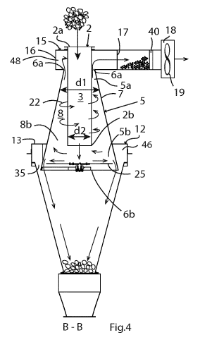
Fig. 4 shows a cross-section B-B through the apparatus shown in figure 2
illustrating the air
flow of material and separated particles in the apparatus.
Fig. 5 shows a cross-section C-C through the apparatus shown in figure 3.
Fig. 6 shows a cross-section D-D through the apparatus shown in figure 3.
Fig. 7 shows another example of an apparatus for separating material according
to the
invention.
Detailed description
Figure 1 shows a perspective view of an example of an apparatus 1 according to
the invention
for separating smaller particles from larger particles in a material including
particles of
different sizes by means of cyclonic separation. Figure 2 shows the apparatus
shown in figure
1 seen from above. Figure 3 shows a cross section A-A through the apparatus
shown in figure
2, and figure 4 shows a cross section B-B through the apparatus. Figure 5
shows a cross section
C-C through the apparatus shown in figure 3, and figure 6 shows a cross
section D-D through
the apparatus shown in figure 3.
The apparatus comprises a separation chamber 5 where separation of the
material takes place
and a feeding pipe 2 for feeding the material to the separation chamber 5, as
shown in figure
4. The feeding pipe 2 is tubular and defines a first channel 3 for guiding
transportation of the
material to the separation chamber 5. The feeding pipe 2 has an inlet opening
for receiving
the material to be separated in an upper end 2a and an outlet opening for
supplying the
CA 03084241 2020-06-02
WO 2019/110451 10
PCT/EP2018/083220
material to the separation chamber 5 at a lower end 2b of the feeding pipe.
The radius of the
separation chamber continually decreases from the lower end 2b to the upper
end 2a. The
feeding pipe 2 is vertically arranged.
The separation chamber 5 has curved wall 7 surrounding the feeding pipe 2 such
that a second
channel 8 is formed between the feeding pipe and the wall. The second channel
8 has an upper
end 8a and a lower end 8b, as shown in figure 3. The second channel 8 extends
between the
lower end 2b of the feeding pipe and the upper end 5a of the separation
chamber 5. The
curved wall 7 is conically shaped and tapers from the lower end 5b to the
upper end 5a of the
separation chamber. Accordingly, the separation chamber 5 and the second
channel 2 are also
conical and taper from the lower end 5b to the upper end 5a of the separation
chamber. The
feeding pipe and the separation chamber are concentrically arranged. The
second channel 8
is annular and surrounds the feeding pipe 2, as shown in figure 2.
The separation chamber 5 has a larger inner diameter dl than the outer
diameter d2 of the
feeding pipe. The curved wall 7 enables the generation of a rotating flow of
air and particles,
i.e. a cyclone, inside the separation chamber S. Preferably, the separation
chamber 5 is
rotationally symmetric with a circular cross section in order to generate a
smooth flow. The
feeding pipe 2 and the separation chamber 5 are concentrically arranged. The
separation
chamber 5 is conical having a wide end and a narrow end. The separation
chamber 5 has a
first opening 6a at an upper end 5a, and a second opening 6b at a lower end
5b. Since the
curved wall 7 tapers from the second opening 6b to the first opening 6a, the
first opening 6a
is narrower than the second opening 6b. The radius of separation chamber 5 is
continually
decreasing towards the first opening 6a. The second channel 8 is conically
shaped and tapers
from the second opening 6b towards the first opening 6a of separation chamber
S. In this
example, the first opening 6a is annular and surrounds the feeding pipe 2 and
the second
opening 6b is circular.
The feeding pipe 2 penetrates through the first opening 6a of the separation
chamber S. The
feeding pipe 2 protrudes into the separation chamber 5 and ends at a distance
above the
second opening 6b. The maximum size of the separated particles depends on the
length of
the second channel 8, and accordingly on the length of the part of the feeding
pipe 2
protruding into the separation chamber, i.e. the distance between the upper
end 5a of the
separation chamber 5 and the lower end 2b of the feeding pipe. Thus, the
apparatus can be
roughly calibrated by selecting a certain length of the feeding pipe and
adapting the length of
the part protruding into the separation chamber in dependence on the desired
maximum size
of the particles to be separated from the material.
The apparatus further comprises an air inlet unit 12 arranged for supplying
air to the lower
end 8b of the second channel, and an outlet unit 15 arranged at an upper end
8a of the second
channel for discharging air and separated material. In this example, the
outlet unit 15
comprises a curved housing 16 defining a curved fourth channel 48 surrounding
the upper end
CA 03084241 2020-06-02
WO 2019/110451 11
PCT/EP2018/083220
2a of the feeding pipe and arranged in communication with an upper end 8a of
the second
channel. The curved housing 16, and accordingly the fourth channel 48, has an
outlet opening
17 for discharging air and separated material, as shown in figure 5. The
curved housing 16 of
the outlet unit 15 is at least partly ring-shaped and has a central though-
hole for receiving the
feeding pipe 2. In this example, the upper end 5a of the separation chamber 5
is attached to
the outlet unit 15. The central through-hole of the curved housing 16 of the
outlet unit 15 has
an upper circular opening having a diameter corresponding to the outer
diameter d2 of the
feeding pipe and tightly connected to an upper part of the feeding pipe to
provide an airtight
seal between the outlet unit and the feeding pipe. The central through-hole of
the curved
housing 16 of the outlet unit has a lower circular opening having a diameter
corresponding to
the diameter of the upper end 5a of the separation chamber. The upper end 5a
of the
separation chamber 5 is attached to the outlet unit 15 so that the first
opening 6a is arranged
between the second channel 8 and the interior of the curved housing 16 to
allow the rotating
air flow 22 to enter the curved fourth channel 48 of the outlet unit 15, as
shown in figure 3.
Thus, the second channel 8 is in communication with fourth channel 48, i.e.
the interior of the
curved housing 16 of the outlet unit. In this example, the first opening 6a
surrounds the
feeding pipe 2, as shown in figure 5.
In this example, the air inlet unit 12 comprises a curved housing 13
surrounding the separation
chamber 5. The housing 13 defines a curved third channel 46 for the air flow
and has an inlet
opening 14 for receiving the air. The third channel 46 is arranged in
communication with the
lower end 8b of the second channel via a third opening 35 and the second
opening 6b of the
separation chamber, as shown in figure 3. In this example, the third opening
35 is annular and
surrounds the separation chamber. The curved housing 13 of the inlet unit is
attached to the
separation chamber 5 so that the third opening 35 is formed between the
interior of
separation chamber 5 and the curved housing 13 of the air inlet unit to allow
air from the inlet
unit 12 to enter the second opening 6b of the separation chamber. In this
example, the inlet
unit 12 is attached to a lower part of the separation chamber 5. In this
example, the curved
housing 13 of the inlet unit 12 is at least partly ring-shaped and has a
central though-hole for
receiving the separation chamber 5. The central through-hole of the inlet unit
12 has an upper
circular opening having a diameter corresponding to the outer diameter of a
lower part of the
separation chamber and is tightly connected to the separation chamber to
provide an airtight
seal between the inlet unit 12 and the separation chamber 5. The curved
housing 13 of the
inlet unit 12 has a circular opening having a diameter larger than the
diameter of the lower
part of the separation chamber 5 so that the annular third opening 35 is
formed between the
interior of the separation chamber 5 and the curved housing 13 of the inlet
unit to allow air
from the curved channel 46 of the inlet unit 12 to enter second opening 6b of
the separation
chamber 5. Thus, the second channel 8 is in communication with the interior of
the curved
housing 13 of the inlet unit.
CA 03084241 2020-06-02
WO 2019/110451 12
PCT/EP2018/083220
The apparatus further comprises a suction unit 18 connected to the outlet unit
15 for sucking
air from the air inlet unit 12 to the outlet unit 15 so that a rotating air
flow 22 is formed in the
second channel 8 and smaller particles are transported upwards to the outlet
unit 15 by means
of the rotating air flow 22 while larger particles are moved downwards due to
gravity. The
suction unit is disposed outside the separation chamber 5 and the outlet unit
15. The outlet
opening 17 of the outlet unit is operatively connected to the suction unit 18.
Thus, the outlet
unit can be directly or indirectly connected to the suction unit. In one
embodiment, the
suction unit 18 comprises a motor (not shown) and a fan 19 with a variable
speed, as shown
in figure 4. The suction unit 18 may be provided with a control device for
controlling the speed
of the fan. For example, the suction unit comprises a frequency converter
adapted to control
the speed of the fan 19. The maximum size of the separated material depends on
the flow
rate of the air flow 22 in the second channel 8, which depends on the speed of
the fan. By
having a fan with a variable speed, it is possible to control the maximum size
of the separated
material by varying the speed of the fan. Suitably, the control device is
designed to allow a
user to vary the speed of the fan so that the user easily can adjust the
maximum size of the
separated material. The maximum size of the separated material depends on the
length of the
second channel as well as the flow rate of the air flow in the second channel.
Thus, the
apparatus can firstly be roughly calibrated by adjusting the part of the
feeding pipe protruding
into the separation chamber, and then fine-tuned by adjusting the speed of the
fan. Thus, it is
possible to calibrate the apparatus to achieve a desired size of the separated
material with
high accuracy.
The apparatus also comprises a lower part 37 surrounding the lower end 5b of
the separation
chamber 5 and is attached to the air inlet unit 12. In this example the lower
part 37 is conical.
In an alternative example, the lower part 37 can be cylindrical. In one aspect
of the invention,
the apparatus comprises collector unit 38 for collecting the separated larger
particles. The
collector unit 38 is attached to the lower part 37. The collector unit is
optional.
Suitably, a filter unit 40 is arranged between the suction unit 18 and the
opening 17 of the
outlet unit to prevent small particles from entering the suction unit 18 and
by that reduce the
risk of causing a fire if the small particles enter a motor of the suction
unit, as shown in figure
4. Further, the apparatus may have an air lock 44 arranged to prevent air from
entering the
first channel 3 of the feeding pipe 2 together with the unseparated material,
as shown in figure
7.
In one aspect of the invention, the apparatus comprises an impeller 25
rotatable arranged
below the feeding pipe 2 and at a distance from the lower end 2b of the
feeding pipe, and the
curved wall 7 of the separation chamber surrounds the impeller 25 such that a
gap 27 is
formed between the curved wall 7 and the outer periphery 26 of the impeller,
as seen in figure
3 and 6. Preferably, the impeller is centred in the separation chamber. The
size of the gap 27
should be larger than the size of the largest particles to be separated. For
example, the gap is
larger than 20 mm.
CA 03084241 2020-06-02
WO 2019/110451 13
PCT/EP2018/083220
The second opening 6b of the separation chamber 5 is arranged below the
impeller 25 for
receiving air from the air inlet unit 12, and the air inlet unit 12 is
arranged to supply air to the
second opening 6b of the separation chamber. The impeller 25 is arranged
rotatable about an
axis of symmetry 30 of the separation chamber 5, and the rotation of the
impeller 25 is driven
by means of the rotating air flow 22 caused by the suction unit 18. The
impeller comprises a
centrum plate 28 and a plurality of blades 29 extending from the centrum plate
28 to the outer
periphery 26 of the impeller. The upper surface of the impeller faces the
outlet of the feeding
pipe. The material from the feeding pipe hits the central plate 28 that
pulverizes the material
into particles. For example, the material consists of aggregated particles,
such as lumps, of
different sizes that need to be separated into separate particles before the
smaller particles
can be separated from the larger particles. The impeller causes loosening of
aggregated
material to enable separation of the aggregated material into separate
particles. However,
the impeller 25 is optional. If the material fed to the apparatus is not
aggregated, the impeller
is not needed.
The function of the apparatus will now be explained with reference to the
figures 3, 4, and 5.
The arrows shown in figure 3 and 5 illustrate the air flow through the
apparatus, and the
arrows shown in figure 4 illustrate the flow of material and particles in the
apparatus. When
the suction unit 18 is started, a rotating air flow 22 is generated inside the
separation chamber
5. The rotating air flow 22 forms a cyclone inside the separation chamber. The
suction unit is
tuned so that the flow rate of the rotating air flow 22 allows particles
smaller than a set
maximum size to be moved upwards in the second channel 8 and particles larger
than the set
maximum size to be moved downwards due to gravity acting on the particles.
The suction unit 18 sucks air from the inlet unit 12 to the outlet unit 15
through the second
channel 8, as seen in figure 3. The air flow enters the inlet unit 12 through
the opening 14 and
follows the curved housing 13 of the air inlet unit to cause the air flow to
rotate, as shown in
figure 5. The rotating air flow enters through the annular opening 35 between
housing 13 of
the air inlet unit 12 and the separation chamber 5, and then enters the
separation chamber 5
through the lower end 5b of the separation chamber 5, as shown in figure 3. If
the apparatus
has an impeller 25, the rotating air flow hits the blades 29 of the impeller
and causes the
impeller to rotate. The rotating air flow penetrates through the impeller and
the gap 27. The
rotating air flow 22 enters the lower end 8b of the second channel 8 and
rotates around the
feeding pipe 2 towards the upper end 8a of the second channel, as shown in
figure 3. The
rotating air flow 22 enters the outlet unit 15 through the first opening 6a
between second
channel 8 and outlet unit 15 at the upper end 8a of the second channel 8. The
rotating air flow
22 enters the curved housing 16 of the outlet unit and leaves the outlet unit
through the
opening 17 of the outlet unit, as shown in figure 5.
Material to be separated is fed to the first channel 3 via the upper end 2a of
the feeding pipe
2 and is supplied to the separation chamber 5 at the lower end 2b of the
feeding pipe, as
shown in figure 4. The material hits the central plate 28 of the rotating
impeller 25. When the
material has hit the impeller 25, the material is loosen and small particles
of the material, i.e.
CA 03084241 2020-06-02
WO 2019/110451 14
PCT/EP2018/083220
particles having a size below the set maximum size, are moved upwards in the
separation
chamber 5 by means of the rotating air flow 22, and the larger particles, i.e.
particles having a
size above the set maximum size, are moved horizontally towards the gap 27 by
centrifugal
forces caused by the rotation of the impeller 25, and when the larger
particles reach the gap
27 they will fall down below the impeller where they can be collected. The
smaller particles
will follow the rotating air flow 22 upwards towards the outlet unit 15 and
leave the outlet
unit 15 through the opening 17 of the outlet unit, as shown in figure 5.
The present invention is not limited to the embodiments disclosed but may be
varied and
modified within the scope of the following claims. For example, the separation
chamber, the
air inlet unit and outlet unit can be designed in different ways. In an
alternative example, the
apparatus can be provided with a second air inlet unit disposed in a lower
part of the
apparatus below the first air inlet unit. In alternative embodiments of the
invention, the
second channel can be cylindrical or have the shape of an inverted cone.
Reference list
1 Apparatus for separating particles
2 Feeding pipe
2a Upper end of feeding pipe
2b Lower end of feeding pipe
3 First channel
5 Separation chamber
5a Upper end of the separation chamber
5b Lower end of the separation chamber
6a First opening (outlet) of the separation chamber
6b Second opening (inlet) of the separation chamber
7 Curved wall of the separation chamber
8 Second channel
8a Upper end of the second channel
8b Lower end of the second channel
12 Air inlet unit
13 Curved housing of the air inlet unit
14 Inlet opening of the air inlet unit
15 Outlet unit
16 Curved housing of the outlet unit
17 Opening of the outlet unit
18 Suction unit
19 Fan of the suction unit
22 Rotating flow
25 Impeller
26 Outer periphery of the impeller
27 Gap
28 Centrum plate of the impeller
29 Blades of the impeller
CA 03084241 2020-06-02
WO 2019/110451 15
PCT/EP2018/083220
30 Axis of symmetry of the separation chamber
dl Inner diameter of the separation chamber
d2 Outer diameter of the feeding pipe
35 Third opening between second channel and inlet unit
37 Lower part
38 Collector unit
40 Filter unit
44 Air lock
46 Curved third channel of inlet unit
48 Curved fourth channel of outlet unit