Note: Descriptions are shown in the official language in which they were submitted.
CA 03084276 2020-06-02
WO 2019/115752
PCT/EP2018/084913
PRESSURIZATION OF A SUPPORT STRUCTURE FOR HANDLING OF A PERSON
TECHNICAL FIELD
The present disclosure relates to a support structure, and to a system and
method for controlling the
pressurization of the support structure. According to embodiments presented
herein, the support
structure is adapted to receive a person, and the system is adapted to control
the pressurization of
the support structure such that motion is imparted on the person, in relation
to a base.
BACKGROUND
A total of one in five patients at European health institutions suffer from
pressure sores. The main
.. reason is absence of regular movement. Today's solution is manual turning
of patients done by
health personnel, resulting in serious skin and muscle pain. For health
personnel this means
continuous heavy lifting of patients which results in back pain and
exhaustion. For the health
institutions this is expensive in terms of workload, sick leaves and patient
treatment. In a broader
problem view, the global aging population increases the need for automatic
solutions in the health
sector, as there will not be enough health professionals to assist the
increasing number of elderly
people.
SUMMARY
Embodiments presented herein advantageously reduce the risk of bed sores of
the person, improve
mobility and thereby the independency and quality of life of the person, as
well as reduce the risk of
work related injuries on possible health care providers assisting the person,
among other things.
According to a first aspect, there is provided a system for controlling the
pressurization of a support
structure for handling of a person, the system comprising: a support structure
adapted to be placed
on a base surface, the support structure comprising: i) a body, having a front
surface adapted to
receive the person, and a back surface, the body comprising a row of at least
two elongated sections
.. made substantially of a first, flexible, material, wherein each elongated
section is attached to its
neighboring elongated section, or sections, along its longitudinal side, or
sides, wherein the
elongated sections are adapted to be pressurized; ii) a carrier plate having a
front surface and a back
surface, wherein the carrier plate is made of a second material that is less
flexible than the first
material, wherein the back surface of each elongated section is attached to
the front surface of the
carrier plate in at least one point, wherein, in a pressurized loaded
condition of one or more of the
elongated sections, the carrier plate is adapted to form an at least partially
concavely curved front
surface; and a power unit adapted to pressurize one or more parts of the
support structure that is
adapted to be pressurized, wherein each of said one or more parts of the
support structure that is
adapted to be pressurized comprises at least one of the elongated sections of
the support structure,
.. wherein the one or more parts of the support structure that is adapted to
be pressurized are
configured to be individually pressurized via a respective valve; The system
further comprises one or
more sensors adapted to measure movements of the person and/or variations or
deviations in
pressurized parts of the support structure in the system; and a controller
comprising a data
processor, the data processor being configured to generate a control signal
indicative of individual
pressurization of each part of the support structure that is adapted to be
pressurized via a respective
1
CA 03084276 2020-06-02
WO 2019/115752
PCT/EP2018/084913
valve based at least on sensor measurement data from the one or more sensors,
wherein the
controller is configured to control the power unit to pressurize each part of
the support structure
that is adapted to be pressurized via the respective valve individually in
response to the control
signal.
According to another aspect, there is provided a method for controlling the
pressurization of a
support structure for handling of a person located on the support structure,
the method comprising:
receiving, in a controller connected to the support structure, sensor
measurement data indicating
movement of the person located on the support structure, and/or pressure
changes or other
variations or deviations in pressurized parts of the support structure, from
one or more sensors;
generating, by a data processor comprised in the controller, a control signal
indicative of individual
pressurization of each of the parts of the support structure is are adapted to
be pressurized, based at
least on the received sensor measurement data; and controlling, by the
controller, a power unit
connected to the support structure to individually pressurize each part of the
support structure that
is adapted to be pressurized via a respective valve, based on the control
signal.
According to a further aspect there is provided a computer program loadable
into a memory
communicatively connected or coupled to at least one data processor,
comprising software for
executing the method according to any of the embodiments presented herein when
the program is
run on the at least one data processor.
According to yet another aspect there is provided processor-readable medium,
having a program
recorded thereon, where the program is to make at least one data processor
execute the method
according to of any of the embodiments presented herein when the program is
loaded into the at
least one data processor.
BRIEF DESCRIPTION OF THE DRAWINGS
The invention is now to be explained more closely by means of preferred
embodiments, which are
disclosed as examples, and with reference to the attached drawings.
Figure 1 shows an overview of a system according to one or more embodiments;
Figure 2 shows an overview of a support structure according to one or more
embodiments;
Figure 3a shows a top view of a support structure according to one or more
embodiments, and a
schematic view of a part of a system according to one or more embodiments;
Figure 3b shows a top view of a support structure according to one or more
embodiments, and a
schematic view of a part of a system according to one or more embodiments;
Figure 4 shows an overview of a support structure according to one or more
embodiments;
Figure 5 shows an overview of a support structure according to one or more
embodiments;
Figure 6 shows an overview of a support structure according to one or more
embodiments;
Figure 7 is a flow chart of a method according to one or more embodiments;
Figure 8 shows an overview of a support structure according to one or more
embodiments;
2
CA 03084276 2020-06-02
WO 2019/115752
PCT/EP2018/084913
Figure 9 shows an overview of a support structure according to one or more
embodiments;
Figure 10 shows an overview of a support structure in combination with a
mattress or bed rest,
according to one or more embodiments;
Figure 11 shows an overview of a support structure in combination with a
mattress or bed rest,
according to one or more embodiments;
DETAILED DESCRIPTION
Introduction
The present disclosure describes a system for controlling the pressurization
of a support structure for
handling of a person, especially a person lying down, to reduce the risk of
bed sores of the person,
improve mobility and thereby the independency and quality of life of the
person, and/or reducing
the risk of work related injuries on possible health care providers assisting
the person. The handling
of the person is in the context of the present disclosure achieved by
adaptively and dynamically
pressurizing a selection of the parts of the support structure that are
adapted to be pressurized, for
example a selection of elongated sections, or groups of elongated sections,
that form the body of the
support structure, thereby obtaining a curvature around the person for example
lying on or leaning
against the support structure. The curvature is adapted and personalized to
the anatomy of the
person and/or the medical or reduced mobility induced needs of the person.
This is achieved by the
individual pressurization of each of the elongated sections, or groups of
elongated sections, that
form the body of the support structure, and possibly also a selection of tilt
cells, or groups of tilt cells,
attached to the back surface of the support structure (the back surface of the
carrier plate), as
further described in connection with the figures. The
pressurization/depressurization, or
inflation/deflation, of the elongated sections and tilt cells of the support
structure is controlled by a
controller, based on sensor feedback and optionally also input provided by a
user of the system, e.g.
an operator.
An example of a problem that can be mitigated using the inventive support
structure is physical
immobility in a person, which leads to low blood flow and constant pressure on
body parts that after
just hours will start developing into pressure ulcers. By keeping constant
movement, controlled
according to embodiments presented herein, the inventors have found that
pressure is relieved in a
way that reduces and heals pressure ulcers.
Another concrete example where the support structure according to embodiments
herein has been
shown to provide a beneficial effect is for persons with multiple sclerosis.
Typically, such persons
regularly need to receive physiotherapy where their muscles are
massaged/stretched/moved in
order to reduce stiffness etc. Embodiments of the present disclosure provide
individualized
movement assistance during sleep or rest, and thereby reduce the need for this
therapy during the
active hours of the persons.
System architecture
Below, embodiments of the inventive system are described in more detail, with
reference to Figs. 1-
6.
3
CA 03084276 2020-06-02
WO 2019/115752
PCT/EP2018/084913
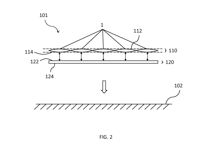
Fig. 1 shows a system 100, according to embodiments of the invention, for
controlling the
pressurization of a support structure for handling of a person. The system 100
comprises a support
structure 101, a power unit 170, one or more sensors 140 and a controller 130.
The support structure is adapted to be placed on a base surface 102, and
comprises a body 110
having a front surface 112 adapted to receive the person, and a back surface
114. An overview of the
parts of the support structure is shown in Figs. 2, 3a and 3b. Fig. 2 shows
the body 110 and the
carrier plate 120 in a cross-sectional as seen along the direction of the
longitudinal extension of the
support structure 101 (corresponding to the direction of the longitudinal axis
A of Fig. 5, or an axis
parallel to axis A). Figs. 3a and 3b show a top view of the support structure
101, as seen when
looking onto the front surface 112 of the body 110, and a schematic view of a
part of the system 100
according to embodiments presented herein.
The body 110 comprises a row of at least two elongated sections 1 made
substantially of a first,
flexible, material. Each elongated section 1 is attached to its neighboring
elongated section, or
sections, 1, along its longitudinal side, or sides, 116. In different
exemplary embodiments, each
elongated section 1 may be attached to its neighboring section or sections 1
by welding, gluing,
sowing or other suitable attachment methods. The elongated sections are
tiltably or rotatably
attached to each other. In other words, for each elongated section 1 there is,
as illustrated in Fig. 5,
defined an axis A extending in the direction of the extension of the elongated
section 1, whereby the
elongated sections are attached in a manner allowing a rotation angle between
the elongated
section 1 and its neighboring elongated section or sections 1 to be altered by
rotation around the
axis A, or an axis parallel to the axis A. This enables the body 110 to curve
in different manners
according to the individual pressurization according to embodiments presented
herein.
The elongated sections 1 are adapted to be pressurized and/or depressurized,
e.g. pneumatically or
hydraulically inflated and/or deflated. Hereinafter, in the context of this
application, the term
pressurize may be used in the meaning of either increasing pressure,
decreasing pressure, inflate or
deflate. The flexible first material allows the elongated sections 1 to change
their shape and/or
volume when they are pressurized. According to one or more advantageous
embodiments, the
elongated sections 1 are configured to be individually pressurized. According
to other advantageous
embodiments, two or more groups of elongated sections 1 are configured to be
individually
pressurized. In different embodiments described herein, either a single
elongated section 1, or a
group comprising two or more elongated sections 1, may be referred to as a
part of the support
structure 101 that is adapted to be pressurized.
The first material may for example be a polymer or other canvas, a nylon based
material, or another
material with suitable properties, including flexibility. The power unit 170
is adapted to pressurize
one or more parts of the support structure that are adapted to be pressurized,
for example one or
more elongated sections 1 and/or one or more tilt cell of the support
structure 101. According to
embodiments, the system 100 comprises, for each part of the support structure
101 that is adapted
to be pressurized, such as the elongated sections 1 and tilt cells, or groups
of elongated sections 1
and/or tilt cells, (described below), a respective valve 104.
Hereinafter, a part of the support structure 101 that is adapted to be
pressurized may for ease of
reading be referred to as a part of the support structure 101.
4
CA 03084276 2020-06-02
WO 2019/115752
PCT/EP2018/084913
A part of the support structure 101 that is adapted to be pressurized may
comprise a single
elongated section or tilt cell connected to a valve 104. This is illustrated
for the elongated sections 1
in Fig. 3a. Alternatively, a part of the support structure 101 that is adapted
to be pressurized may
comprise a group of elongated sections 1 and/or tilt cells connected to a
valve 104. This is illustrated
by the non-limiting example configuration shown in Fig. 3b, wherein the valve
104 is connected to a
part of the support structure 101 comprising two elongated sections 1, the
valve 104' is connected to
a part of the support structure 101 comprising a single elongated section 1,
and the valve 104" is
connected to a part of the support structure 101 comprising two elongated
sections 1, but many
other options for grouping elongated sections 1 and/or tilt cells 6A, 63, 14
are of course feasible.
In some embodiments, the support structure 101 comprises a selection of at
least two of the
following:
¨ one or more parts that consist of a single elongated section 1 connected
to a respective valve
104;
¨ one or more parts that consist of a single tilt cell connected to a
respective valve 104; and
¨ one or more parts that comprise of a group of elongated sections 1 and/or
tilt cells, each
group being connected to a respective valve 104.
In one or more embodiments, each part of the support structure 101 that is
adapted to be
pressurized is configured to be individually pressurized via a respective
valve 104. In embodiments
wherein a part of the support structure 101 that is adapted to be pressurized
is a single elongated
section 1 or tilt cell, the elongated sections 1 and tilt cells are configured
to be individually
pressurized via a respective valve 104, as schematically illustrated in Fig.
3a. In embodiments wherein
a part of the support structure 101 that is adapted to be pressurized is a
group of elongated sections
1 and/or tilt cells, the groups are configured to be individually pressurized
via a respective valve 104,
as schematically illustrated in Fig. 3b.
The data processor 150 is configured to generate a control signal 135
indicative of individual
pressurization of each part of the support structure 101 that is adapted to be
pressurized via a
respective valve 104, based at least on sensor measurement data from the one
or more sensors 140;
and the controller 130 is configured to control the power unit 170 to
pressurize each part of the
support structure 101 that is adapted to be pressurized via a respective valve
104 individually in
response to the control signal 135. Controlling the power unit 170 to
pressurize/regulate the
pressure in each part of the support structure 101 that is adapted to be
pressurized via a respective
valve 104 individually, the data processor may be configured to obtain sensor
measurement data
from the pressure sensors 140 and data from the database 190, compare the
sensor measurement
data to the data obtained from the database 190, and generate a control signal
indicative of
starting/stopping the power unit 170 and/or open and/or close a selection of
the valves 104.
The power unit 170 may for example be an air pump, a compressor or any other
suitable power unit
configured to perform hydraulic or pneumatic pressurization. The power unit
170 may in some
embodiments be controlled by the controller 130 using for example pulse width
modulation or other
frequency controlling methods.
The carrier plate 120 has a front surface 122 and a back surface 124. The
carrier plate 120 is made of
a second material that is flexible, but less flexible than the first material.
In other words, the second
5
CA 03084276 2020-06-02
WO 2019/115752
PCT/EP2018/084913
material is stiffer than the first material. As illustrated by the double
arrows in Fig. 4, the back surface
114 of each elongated section 1 is attached to the front surface 122 of the
carrier plate 120 in at
least one point 4. Thereby, in a pressurized loaded/at least partly inflated
condition of one or more
of the parts adapted to be pressurized that comprise at least one elongated
section 1, the carrier
plate 120 is adapted to form an at least partially concavely curved front
surface 122, as shown in Fig.
4. In the figures, the curvature of the support structure 101 is shown as
being symmetric. However,
as explained herein, all parts adapted to be pressurized that comprise at
least one elongated section
1 are configured to be individually pressurized. Thereby, the curvature of the
support structure 101
may be asymmetric, with the only condition that the carrier plate 120 is
adapted to form an at least
.. partially concavely curved front surface 122, because all the elongated
sections 1 are located on the
front side of the carrier plate 120. In Fig. 4, this is further illustrated by
the distances D1 and D2,
wherein D1 represents the distance from the latitudinal center of a first
elongated section 1 to the
latitudinal center of its neighboring elongated section 1 as seen from the
back surface 114 of the
body 110, and wherein D2 represents the distance from the latitudinal center
of the first elongated
section 1 to the latitudinal center of the neighboring elongated section 1 as
seen from the front
surface 112 of the body 110. When none of the parts adapted to be pressurized
(elongated sections
1, groups of elongated sections 1, and/or tilt cells 6a, 6b, 14) are
pressurized, D1 and D2 are equal, or
very close to equal. However, when one or more of the parts adapted to be
pressurized that
comprise at least one elongated section 1 are in a pressurized loaded/at least
partly inflated
condition, the distance D2 will be reduced, whereby the distance D1 becomes
bigger than the
distance D2 for all pairs of neighboring elongated sections 1 wherein at least
one of the elongated
sections 1 in the pair is in a pressurized loaded/at least partly inflated
condition. In other words, the
carrier plate 120 obtains an at least partially concavely curved front surface
122.
As the second material is stiffer than the first material, the curvation of
the carrier plate provides
support for and helps retain the shape obtained by pressurizing the at least
one elongated section 1
when a person is lying, or sitting, on the support structure 101.
In some embodiments, like the ones illustrated in Fig. 10 and 11, the system
100 may comprise an
integrated mattress or bed rest 103, or be intended for use with a separate
mattress or bed rest 103.
In other words, a mattress or bed rest 103 may be an integrated part of the
support structure 101, or
a separate part that the support structure 101 is adapted to receive on its
top surface, wherein the
support structure 101 is further configured to receive a person on top of the
mattress or bed rest
103. In some embodiments, the support structure 101 of the system 100 may be
placed under a
mattress or bed rest 103 and used in a bed for example in a home environment
or at a health care or
elderly care facility. In the context of this disclosure, when it is stated
that something is received or
located on, or a person is lying or sitting on, the support structure 101,
this also includes the case
where there is a mattress, bed rest and the like placed between the support
structure 101 and the
object or person.
Referring again to Fig. 1, the one or more sensors 140 comprised in the system
100 are adapted to
measure parameters such as for example the internal pressure of a respective
part of the support
structure 101, wherein the one or more sensors 140 comprise one or more
pressure sensor, or
acceleration of a respective part of the support structure 101, wherein the
one or more sensors 140
comprise one or more accelerometer configured to measures rotation (X, Y and Z
coordinate) of the
elongated section or tilt cell in which it is comprised. The controller 130 is
communicatively
6
CA 03084276 2020-06-02
WO 2019/115752
PCT/EP2018/084913
connected to a data processor 150. The data processor 150 may be
comprised/integrated in the
controller 130 (as in the example shown in the figure), or be a unit separate
from the controller 130.
The data processor 150 is configured to receive sensor data indicative of the
measured parameters
from at least one of the one or more sensors 140, and to generate a control
signal 135 indicative of
.. individual pressurization objectives for each of the elongated sections 1,
or other parts of the support
structure 101, based at least on the sensor data received from the at least
one of the one or more
sensors 140. In one or more embodiments, the data processor 150 may be
configured to process the
received sensor data, for example by determining, based on pressure data
and/or acceleration data
measured by the one or more sensors, information regarding movements of the
person and/or
relative movement of parts of the support structure 101, for example tilting
of one or more
elongated section and/or tilt cell. According to such embodiments, the data
processor 150 may
generate a control signal 135 indicative of individual pressurization
objectives for each of the
elongated sections 1, or other parts of the support structure 101, based at
least on the processed
sensor data, for example information regarding movements of the person and/or
relative movement
.. of parts of the support structure 101. The sensors 140 may be configured to
measure, and possibly
also send, data either continuously or discretely at predetermined time
intervals, such that real time
or close to real time measurement data, and consequently real time or close to
real time adaptive
pressure controlling, is enabled.
Since pressurization of one or more elongated section 1 and/or tilt cell
causes rotation of the support
structure 101, rotation caused by the person moving, tilt cells being
pressurized etc. is directly
detectable by the data processor 150, in real time or close to real time,
which enables the real time,
or close to real time, controlling of the power unit 170 by the controller 130
in response to the
detected rotation. The same is of course true for other types of inline
sensors used, such as for
example the pressure sensors described herein. Thereby, the movement patterns
of the support
structure can be controlled and the given individual pressurization objectives
can be updated in real
time to optimize the result. Pressure changes and/or rotation of one or more
elongated section
and/or tilt cell may be caused by for example temperature buildup in the
environment, the
temperature of the person on the support structure 101, hence adjusting or
introducing new or old
air/liquid in the system, and/or deviations caused by such as potential
leakage, blockage and other
negative causes, etc. In some embodiments, information about the progress of
the pressurization
and/or information on how well the system is performing (good, bad neutral for
example) is fed back
to the database 190. This information can be used by the system 100 to learn
and improve its
functionality, for example via logic comprised in a machine learning module
180. Once enough data
has been stored in the database 190, then the system 100 will become more or
less autonomous. In
one or more embodiments presented herein, the control data, such as the
control signal 135,
provided by the system 100 may always be overridden by a human user providing
input via a user
interface 160, as presented herein.
In a non-limiting use case example, a respective given tilt value to be
reached by one or more parts
of the support structure 101 may be set in the system 100. In this example,
the support structure 101
may be halfway from its original position to the given tilt value(s) and the
data processor 150 is
aware of this from the sensor data, continuously or discretely sent to and
received by the data
processor 130 from the one or more sensors 140. From the received sensor data,
the data processor
may be configured to determine for example the tilt angle, compared to a
defined starting value, of a
7
CA 03084276 2020-06-02
WO 2019/115752
PCT/EP2018/084913
part of the support structure 101 associated with a specific accelerometer or
other sensor adapted to
measure a tilt angle. Also, by measuring the internal pressure via one or more
pressure sensor
associated with one or more parts of the support structure 101, the data
processor 150 can
determine whether the person is moving, e.g. by analyzing changes in pressure
in one or more parts
of the support structure 101 between two measurements, a change compared to a
given starting
value, or continuous change over time. For example, the analysis may show that
the pressure in a
part located at one side of the support structure increases while the pressure
in a part at an opposing
side of the support structure decreases, the data processes may interpret this
as the person moving
on the support structure 101, i.e. the center of gravity of the person is
moving from one side of the
support structure 101 to the other. Based on this information, the data
processor 150 may be
configured to generate a control signal 135 indicative of individual
pressurization objectives for each
of the parts of the support structure 101 that are adapted to be pressurized.
In a non-limiting
embodiment, this may mean that the data processor 150 generates a control
signal 135 indicative of
individual pressurization objectives for each of the elongated sections 1, for
use by the controller
130. In another non-limiting embodiment, this may mean that the data processor
150 generates a
control signal 135 indicative of individual pressurization objectives for each
of two or more groups of
elongated sections 1, for use by the controller 130. The power unit 170 is
adapted to pressurize one
or more of the parts of the support structure 101 that are adapted to be
pressurized, for example
each of the elongated sections 1, each of the tilt cells, or each of the
groups of elongated sections 1
and/or tilt cells, and the controller 130 is configured to control the power
unit 170 to pressurize the
parts of the support structure 101 that are adapted to be pressurized
individually in response to the
control signal 135, i.e. according to the individual pressurization objectives
indicated in/defined by
the control signal 135.
In some embodiments, the sensors 140 may be inline sensors located within each
of the elongated
sections 1 and/or tilt cells described herein, thereby enabling continuous
measurement of the
pressure and/or other parameters of pressurized parts of the system 100 and
providing feedback to
the controller 130 and data processor 150 for dynamic adaptation of the
pressure. This enables
optimized adaptation to e.g. the anatomy, the sleep patterns and/or the
movement patterns of the
person on or enclosed by the support structure 101. In one or more
embodiments, the inline sensors
are configured to measure real time pressure values, thereby enabling the
controller 130 to reinitiate
any given state during operation of the system 100. Other input may also be
provided to the
controller 130, and taken into consideration, e.g. provided via an input
device, a user interface,
based on machine learning and/or a training data library, etc.
In some embodiments, the sensors 140, which provide feedback to the controller
130, comprise
inline pressure sensors, which in this context is defined as sensors
configured to measure an internal
pressure in different parts of the system, e.g. in each of the elongated
sections 1 and/or tilt cells. In
difference to sensors measuring only externally induced pressure, measurement
and feedback of
internal pressure enables the inflated/pressurized parts of the system to
completely
deflate/depressurize and keep the controller informed of the exact progress of
the
deflation/depressurizing process. This may advantageously be used for a number
of purposes, such
as e.g. initiating the initial settings, or enabling better control over the
pressurization of the
elongated sections 1 and/or tilt cells of the support structure, by providing
real time feedback to the
controller 130 and enabling determination of exactly where in the
pressurization process the system
100 is at any given time.
8
CA 03084276 2020-06-02
WO 2019/115752
PCT/EP2018/084913
The individual pressurization objectives relate to achieving desired movement
/movements to
acquire certain conditions, and may according to some non-limiting examples
comprise a selection
of: very slowly turning a person from side to side (tilting back and forth)
during the night, giving them
the movement, and hence pressure reduction, better blood flow and relaxation
and softening of
muscles etc., without waking them up; in other ways keeping the person in
constant movement,
hence relieving pressure, giving better blood flow, softens the muscles etc.;
providing the movement
or movement scheme that an healthy/fully mobile person can do automatically,
for example sitting
up, getting out of bed, rolling onto the side or from the side to the back
etc. Since the support
structure is flexible in the longitude direction, this makes it possible to
give movement stimuli even if
the support structure is presently in the upright position, i.e. that the
upper part 111 has been tilted
in relation to the middle part 112. For any of the embodiments described
herein, the system 100 may
further comprise a user interface 160 configured to forward user input
parameters to the data
processor 150. The data processor 150 is in these embodiments configured to
receive user input
parameters from the user interface 160. The user input parameters are in these
embodiments
preferably generated in response to user commands entered via by a user
interacting with one or
more input devices connected to the user interface 160. The one or more input
devices may
comprise a keyboard and/or computer mouse or other pointing device,
touchscreen or any other
suitable input device. The input may be provided via a graphical user
interface (GUI) presented on a
display by the user interface 160.
In some embodiments, the system 100 may further comprise a database 190
configured to store
information and parameters relating to individual pressurization objectives
for the parts of the
system 100 that can be pressurized by the pressure unit 170. The database 190
may further be
configured to store such information and parameters in relation to a selection
of: unique user data
identifying the person to be placed on the system 100; experience based data
on preferable pressure
settings for each identified person; experience based data on preferable
pressure settings depending
decrease the risk of bedsores or the like, for obtaining good sleeping
quality, for helping the person
performing a movement or a series of movements, etc.
In one or more embodiments, the database 190 is updated with parameters
obtained from the one
or more sensors 140, manual user input via the user interface 160, information
from the machine
learning module 180 and/or feedback from other units of the system 100
obtained during operation.
The information received in the database 190 may comprise for example as how
long the person has
been in on the support structure 101 (which may in some cases correlate to how
long the person has
been in bed), the medical or other needs of the person, any issues occurring,
etc., basically any type
of information that can be measured by a sensor or input manually and that may
be relevant to the
controlling of the pressurization/the individual pressurization objectives.
The controller 130 may
further be configured to receive input parameters from the database 190, and
to generate the
control signal 135 based also on the input parameters received from the
database 190, in
combination with input parameters obtained in any of the embodiments above.
In some embodiments, the system 100 comprises a machine learning module 180,
which may be
configured to generate experience based data on preferable pressure settings
for different persons
and/or medical situations or defined aims to be achieved. In order to generate
the experience based
data, the machine learning module 180 may be configured to receive and process
information and
9
CA 03084276 2020-06-02
WO 2019/115752
PCT/EP2018/084913
parameters stored in the database 190, sensor data from the one or more
sensors 140, user input
parameters obtained via the user interface 160 and/or data from the controller
130 indicative of
individual pressurization objectives for current or previous applications. The
machine learning
module may further be configured to send experience based data to the
controller 130, and the
controller 130 may further be configured to generate an control signal 135
based on the input
parameters received from the machine learning module 180, in combination with
input parameters
obtained in any of the embodiments above.
In some embodiments, illustrated in Figs. 4 and 5, the wherein the parts of
the support structure 101
that are adapted to be pressurized via a respective valve 104 further
comprise, along a first
longitudinal side of the support structure 101, which corresponds to along an
axis parallel with an
axis A of any the elongated sections land attached to the back surface 124 of
the carrier plate 120,
two or more inflatable lateral tilt cells 6A; and along a second longitudinal
side of the support
structure 101, which corresponds to along an axis parallel with an axis A of
any the elongated
sections 1 and attached to the back surface 124 of the carrier plate 120, two
or more inflatable tilt
cells 6B, wherein the two or more inflatable lateral tilt cells 6A, 6B on the
respective side are adapted
to, when in a pressurized loaded (at least partly inflated) condition, tilt
the body 110 and the carrier
plate 120 around the longitudinal axis A. The control signal 135 may further
be indicative of
individual pressurization objectives of the two or more inflatable tilt cells
6A, 6B of each respective
side of the system 100, whereby the controller 130 may be configured to also
individually control the
pressurization of each of the two or more inflatable lateral tilt cells 6A, 6B
of each side in response to
the control signal 135. Fig. 6, illustrates such a scenario, wherein the
lateral tilt cell 6A has just been
pressurized (inflated) and lateral tilt cell 6B has been depressurized
(deflated), thereby causing the
support structure to rotate around an axis parallel to the axis A.
In a non-limiting example of using the present system 100 for relieving
pressure in an immobile
person or improve the sleeping quality of a person, e.g., the controller 130
may control the
pressurization of the elongated sections 1 and the lateral tilt cells 6A, 6B
through pneumatic or
hydraulic pressure such that the body 110 of the support structure 101 slowly
curves around a
person lying on it to ensure good support, followed by turning/tilting up to
30 degrees from side to
side during the hours of the night, by continuously pressurizing and
depressurizing the lateral tilt cells
6A, 6B according to a predetermined pattern, possibly adapted over time based
on continuous
feedback from the sensors 140 of the system 100. The procedure is
advantageously un-noticeable for
the person as the movement is done slowly and gentle.
The body 110 may in different embodiments comprise at least two parts that are
tiltable relative to
each other around an axis perpendicular to their longitudinal sides, and
arranged on respective sides
of an intermediate flexible area 10, wherein the at least two parts are
connected via one or more
respective intermediate flexible area 10 made of flexible material and being
adapted to change its
shape when the at least two parts are tilted relative to each other. The
carrier plate 120 may
correspondingly comprise at least two separate parts arranged on respective
sides of the
intermediate flexible area 10. As illustrated in Figs. 5, 8 and 9, the body
110 may for example
comprise an upper part 111, a middle part 112 and a bottom part 113, wherein
the upper part 111
and the middle part 112 are tiltable relative to each other around an axis
perpendicular to their
longitudinal sides and arranged on respective sides of a first intermediate
flexible area 10, and
wherein the middle part 112 and the bottom part 113 are tiltable relative to
each other around an
CA 03084276 2020-06-02
WO 2019/115752
PCT/EP2018/084913
axis perpendicular to their longitudinal sides and arranged on respective
sides of a second
intermediate flexible area 10, and wherein the at least two separate parts of
the carrier plate 120
comprises a corresponding upper part 121, middle part 122 and bottom part 123.
In one or more embodiments, the parts of the support structure (101) that are
adapted to be
pressurized via a respective valve 104 further comprises one or more
inflatable longitudinal tilt cell
14, attached to the back surface 124 of a respective part of the carrier plate
120. In Fig. 8, there is
illustrated an embodiment wherein a single inflatable longitudinal tilt cell
14 is attached to the back
surface 124 of the upper part 121 of the carrier plate. The one or more
inflatable longitudinal tilt cell
14 may be adapted to, when in a pressurized loaded (at least partially
inflated) condition, tilt a part
.. of the body 110 to which the selected part of the carrier plate 120 is
attached, in the example if Fig. 8
corresponding to the upper part 111, relative to the neighboring part or parts
of the body 110, such
that the person on the support structure 101 is for example aided in sitting
up.
Of course, the system 100 described herein is not limited to a certain number
of parts for either the
body or the carrier plate, any suitable number may apply. A division of the
body into two tiltable
parts and the carrier plate into at least two parts, wherein the division
between the carrier plate
parts is co-located with the division of the body parts, is sufficient to
enable a folding motion to assist
a person lying on the system to for example lift his/her head or come to a
more upright sitting
position, when combined with the one or more inflatable longitudinal tilt
cells 14. The pressurization
objective, expressed in the form of a control signal 135 and used by the data
processor to control the
pressure unit 170 to pressurize the elongated elements 1, inflatable lateral
tilt cells 6A and 68 and
the one or more inflatable longitudinal tilt cell 14 would be to pressurize to
achieve the aim of
helping the person sit up. This pressurization objective may have been used
before, for the same
person or a different person, whereby preset settings may be obtainable from
the database 190 or
the machine learning module 180. Alternatively, the one or more sensors 140
may register
movement by the person, which the data processor can interpret as an attempt
to switch position,
whereby the data processor 130 computes a suitable pressurization pattern/flow
to assist the person
in continuing the motion, and generates a control signal based on the
calculation, whereby the
controller 130 controls the pressure unit 170 to pressurize the elongated
sections 1 and the lateral
tilt cells 6A, 68 and longitudinal tilt cell, or cells, 14 accordingly. With
the three parts described
above: upper, middle and bottom (see Figs. 5 8 and 9), more fine-tuned
movements can be achieved.
The number of parts/divisions may hence be adapted according to the intended
application of the
system.
Furthermore, if the body 110 and carrier plate 120 are divided into a large
number of respective
parts, as exemplified in Fig. 9, the support structure 101 can be folded, or
even rolled up, for easier
storage and transportation. Folding is of course possible to some extent if
there are at least two
parts, but the optimal number of parts for folding and/or rolling up the
support structure 101 may
vary depending on the materials used and on how the support structure 101 is
intended to be used.
For example, three parts (or more) enables the support structure 101 for use
with a regular bed in
hospitals; nursing homes, etc., which typically comprise three tiltable parts
that the support structure
101 can be configured to mirror. The material of the carrier plate 120 may
further advantageously be
selected such that it is stiff enough to maintain any shape that the carrier
plate 120 takes during
pressurization, and return to its initial shape, i.e. substantially planar,
after depressurization of the
11
CA 03084276 2020-06-02
WO 2019/115752
PCT/EP2018/084913
body 110. In other words, the material should not be such that any plastic
deformation takes place.
The thickness of the carrier plate 110 may be selected depending on
circumstances such as the
material used and the intended application of the support structure 101. If
the carrier plate 120 can
be kept as thin as possible for the selected material, while still maintaining
correct stiffness and as
described above, this is advantageous as it leads to low weight, small size,
and optimized folding,
rolling, transportation and folding properties.
The power unit 170 may be adapted to pressurize the one or more lateral tilt
cells 6A, 63 and/or
longitudinal tilt cell, or cells, 14. Correspondingly, the control signal 135
may further be indicative of
individual pressurization of each of the one or more lateral tilt cells 6A, 63
and/or longitudinal tilt
cell, or cells, 14, in embodiments wherein each of the one or more lateral
tilt cells 6A, 63 and/or
longitudinal tilt cell, or cells, 14 define separate parts of the support
structure 101. The controller 130
may in these embodiments further be configured to control the power unit 170
to pressurize one or
more lateral tilt cells 6A, 63 and/or longitudinal tilt cell, or cells, 14
individually, based on the control
signal 135.
The units of the system 100 may be configured to use any suitable wired and/or
wireless
communication technologies known in the art for communicating with each other.
The solution according to embodiments presented herein empowers user by
restoring control over
their own movements. This means no disturbance and pain from getting manually
turned. For health
personnel this means no heavy lifting and increased time for patient care. For
hospitals it means
reduced cost.
Intended user groups are for example elderly people who have mobility
difficulties, people with
neurological disorders who have similar challenges due to stiffness in the
body, people suffering from
poor blood circulation, poor air flow, poor digestion or poor sleep quality,
etc., who would all benefit
greatly from the solution according to embodiments presented herein The
support structure could
be used in nursing homes or hospitals, as well as at home for home nursing or
for personal use by
private individuals.
Method embodiments
Fig. 7 shows a method according to one or more embodiments for controlling the
pressurization of a
support structure for handling of a person located on the support structure,
comprising:
In step 710: receiving, in a controller connected to the support structure,
sensor measurement data
indicating movement of the person located on the support structure, and/or
pressure changes or
other variations or deviations in pressurized parts of the support structure,
from one or more
sensors.
In step 720: generating, by a data processor comprised in the controller, a
control signal indicative of
individual pressurization of each of the parts of the support structure that
is adapted to be
pressurized, based at least on the received sensor measurement data.
In different embodiments, a part of the support structure may comprise a
single elongated section 1,
a single tilt cell, or any group or combination of elongated sections 1 and/or
tilt cells.
12
CA 03084276 2020-06-02
WO 2019/115752
PCT/EP2018/084913
In one or more embodiments, the method further comprises receiving, via a user
interface, user
input parameters. According to these embodiments, generating the control
signal may further be
based on the received user input parameters.
In one or more embodiments, the method further comprises receiving, in the
data processor, input
from a machine learning module. According to these embodiments, generating the
control signal
may, in combination with the sensor measurement data and optionally also the
user input
parameters, further be based on the received input from the machine learning
module.
In step 730: controlling, by the controller, a power unit connected to the
support structure to
individually pressurize each part of the support structure that is adapted to
be pressurized, via a
respective valve, based on the control signal.
The pressurization may be pneumatically or hydraulically induced.
Further embodiments
All of the process steps, as well as any sub-sequence of steps, described with
reference to Figures 7
above may be controlled by means of a programmed data processor. Moreover,
although the
embodiments of the invention described above with reference to the drawings
comprise a data
processor and processes performed in at least one processor, the invention
thus also extends to
computer programs, particularly computer programs on or in a carrier, adapted
for putting the
invention into practice. The program may be in the form of source code, object
code, a code
intermediate source and object code such as in partially compiled form, or in
any other form suitable
for use in the implementation of the process according to the invention. The
program may either be
a part of an operating system, or be a separate application. The carrier may
be any entity or device
capable of carrying the program. For example, the carrier may comprise a
storage medium, such as a
Flash memory, a ROM (Read Only Memory), for example a DVD (Digital
Video/Versatile Disk), a CD
(Compact Disc) or a semiconductor ROM, an EPROM (Erasable Programmable Read-
Only Memory),
an [[PROM (Electrically Erasable Programmable Read-only Memory), or a magnetic
recording
medium, for example a floppy disc or hard disc. Further, the carrier may be a
transmissible carrier
such as an electrical or optical signal which may be conveyed via electrical
or optical cable or by radio
or by other means. When the program is embodied in a signal which may be
conveyed directly by a
cable or other device or means, the carrier may be constituted by such cable
or device or means.
Alternatively, the carrier may be an integrated circuit in which the program
is embedded, the
integrated circuit being adapted for performing, or for use in the performance
of, the relevant
processes.
In one or more embodiments, there may be provided a computer program loadable
into a memory
communicatively connected or coupled to at least one data processor, e.g. the
data processor 150,
comprising software for executing the method according any of the embodiments
herein when the
program is run on the at least one data processor 150.
In one or more further embodiment, there may be provided a processor-readable
medium, having a
program recorded thereon, where the program is to make at least one data
processor, e.g. the data
processor 150, execute the method according to of any of the embodiments
herein when the
program is loaded into the at least one data processor.
13
CA 03084276 2020-06-02
WO 2019/115752 PCT/EP2018/084913
The invention is not restricted to the described embodiments in the figures,
but may be varied freely
within the scope of the claims.
14