Note: Descriptions are shown in the official language in which they were submitted.
- 1 -
EARTH-BORING TOOLS HAVING A GAUGE REGION
CONFIGURED FOR REDUCED BIT WALK AND
METHOD OF DRILLING WITH SAME
TECHNICAL FIELD
The disclosure, in various embodiments, relates generally to earth-boring
tools, such
as drill bits, having radially and axially extending blades. More
particularly, the disclosure
relates to drill bits including a cutting element mounted in the gauge region
thereof to
decrease deviations of the drill bit while drilling a straight portion of a
borehole.
BACKGROUND
Rotary drill bits are commonly used for drilling boreholes or wellbores in
earth
formations. One type of rotary drill bit is the fixed-cutter bit (often
referred to as a -drag"
bit). The process of drilling an earth formation may be visualized as a three-
dimensional
process, as the drill bit may not only penetrate the formation linearly along
a vertical axis, but
is either purposefully or unintentionally drilled along a curved path or at an
angle relative to a
theoretical vertical axis extending into the earth formation in a direction
substantially parallel
to the gravitational field of the earth, as well as in a specific lateral
direction relative to the
theoretical vertical axis. The term -directional drilling," as used herein,
means both the
process of directing a drill bit along some desired trajectory through an
earth formation to a
predetermined target location to form a borehole, and the process of directing
a drill bit along
a predefined trajectory in a direction other than directly downwards into an
earth formation in
a direction substantially parallel to the gravitational field of the earth to
either a known or
unknown target.
Several approaches have been developed for directional drilling. For example,
positive displacement (Moineau) type motors as well as turbines have been
employed in
combination with deflection devices such as bent housings, bent subs,
eccentric stabilizers,
and combinations thereof to effect oriented, nonlinear drilling when the bit
is rotated only by
the motor drive shaft, and linear drilling when the bit is rotated by the
superimposed rotation
of the motor shaft and the drill string.
Other steerable bottom hole assemblies are known, including those wherein
deflection
or orientation of the drill string may be altered by selective lateral
extension and retraction of
one or more contact pads or members against the borehole wall. One such system
is the
AutoTrakIm drilling system, developed by the INTEQ operating unit of Baker
Hughes, a GE
Date Recue/Date Received 2021-09-02
- 2 -
company, LLC, assignee of the present invention. The bottom hole assembly of
the
AutoTrakIm drilling system employs a non-rotating sleeve through which a
rotating drive
shaft extends to drive the bit, the sleeve thus being decoupled from drill
string rotation. The
sleeve carries individually controllable, expandable, circumferentially spaced
steering ribs on
its exterior, the lateral forces exerted by the ribs on the sleeve being
controlled by pistons
operated by hydraulic fluid contained within a reservoir located within the
sleeve. Closed
loop electronics measure the relative position of the sleeve and substantially
continuously
adjust the position of each steering rib so as to provide a steady lateral
force at the bit in a
desired direction. Further, steerable bottom hole assemblies include placing a
bent adjustable
kick off (AKO) sub between the drill bit and the motor. In other cases, an AKO
may be
omitted and a side load (e.g., lateral force) applied to the drill string/bit
to cause the bit to
travel laterally as it descends downward.
The processes of directional drilling and deviation control are complicated by
the
complex interaction of forces between the drill bit and the wall of the earth
formation
surrounding the borehole. In drilling with rotary drill bits and, particularly
with fixed-cutter
type rotary drill bits, it is known that if a lateral force is applied to the
drill bit, the drill bit
may -walk" or -drift" from the straight path that is parallel to the intended
longitudinal axis
of the borehole. Many factors or variables may at least partially contribute
to the reactive
forces and torques applied to the drill bit by the surrounding earth
formation. Such factors
.. and variables may include, for example, the -weight on bit" (WOB), the
rotational speed of
the bit, the physical properties and characteristics of the earth formation
being drilled, the
hydrodynamics of the drilling fluid, the length and configuration of the
bottom hole assembly
(BHA) to which the bit is mounted, and various design factors of the drill
bit.
DISCLOSURE
In some embodiments, a drill bit for removing subterranean formation material
in a
borehole comprises a bit body comprising a longitudinal axis, a blade
extending radially
outward from the longitudinal axis along a face region of the bit body and
extending axially
along a gauge region of the bit body, and a cutting element on the blade in
the gauge region,
the cutting element located proximate to an uphole edge. A remainder of the
gauge region is
free of cutting elements mounted thereon.
In further embodiments, a drill bit for removing subterranean formation
material in a
borehole comprises a bit body comprising a longitudinal axis, a blade
extending radially
outward from the longitudinal axis along a face region of the bit body and
extending axially
Date Recue/Date Received 2021-09-02
- 3 -
along a gauge region of the bit body, and at least one cutting element on the
blade in the
gauge region. The at least one cutting element is located in an upper quartile
of the at least
one blade in the gauge region such that a remainder of the gauge region beyond
the upper
quartile is free of cutting elements mounted thereon.
In other embodiments, a method of drilling a borehole in a subterranean
formation
comprises rotating a bit about a longitudinal axis thereof and engaging a
subterranean
formation with at least a portion of a gauge region of a blade of the bit. The
gauge region
comprises a cutting element on the blade in the gauge region, the cutting
element located
proximate to an uphole edge of the blade in the gauge region and a remainder
of the gauge
region is free of cutting elements mounted thereon. The method further
comprises increasing
a tilt angle of the bit such that the cutting element and the remainder of the
gauge region
consecutively engaged with the subterranean formation with increasing tilt
angle.
In other embodiments, a drill bit for removing subterranean formation material
in a
borehole comprises: a bit body comprising a longitudinal axis; at least one
blade extending
radially outward from the longitudinal axis along a face region of the bit
body and extending
axially along a gauge region of the bit body, the at least one blade in the
gauge region
comprising: a first portion comprising a first outer surface at least
partially defining a first
diameter of the bit body; and a second portion comprising a second outer
surface at least
partially defining a second diameter of the bit body, the first diameter being
smaller than the
second diameter; and a single cutting element on the first portion of the at
least one blade in
the gauge region, the single cutting element being located proximate to an
uphole edge of the
at least one blade in the gauge region, a cutting face of the single cutting
element being
radially recessed relative to an outer diameter of the drill bit and extending
radially beyond
the first outer surface, wherein a remainder of the gauge region of the at
least one blade is
free of cutting elements mounted thereon.
In other embodiments, a directional drilling system comprises a steerable
bottom hole
assembly operably coupled to the drill bit as described in the immediately
preceding
paragraph.
In other embodiments, a drill bit for removing subterranean formation material
in a
.. borehole comprises: a bit body comprising a longitudinal axis; at least one
blade extending
radially outward from the longitudinal axis along a face region of the bit
body and extending
axially along a gauge region of the bit body, the at least one blade in the
gauge region
comprising: a first portion comprising a first outer surface at least
partially defining a first
diameter of the bit body; and a second portion comprising a second outer
surface at least
Date Recue/Date Received 2021-09-02
- 3a -
partially defining a second diameter of the bit body, the first diameter being
smaller than the
second diameter; and at least one cutting element on the first portion of the
at least one blade
in the gauge region, the at least one cutting element being located in an
upper quartile of the
at least one blade in the gauge region such that a remainder of the gauge
region beyond the
upper quartile is free of cutting elements mounted thereon, a cutting face of
the at least one
cutting element being radially recessed relative to an outer diameter of the
drill bit and
extending radially beyond the first outer surface in the upper quartile of the
at least one blade
in the gauge region.
In other embodiments, a method of drilling a borehole in a subterranean
formation
comprises: rotating a bit about a longitudinal axis thereof within the
borehole; engaging a
sidewall of the borehole with at least a portion of a gauge region of at least
one blade of the
bit, the gauge region comprising: a cutting element on the at least one blade
in the gauge
region, the cutting element being located proximate to an uphole edge of the
at least one
blade in the gauge region, wherein a remainder of the gauge region is free of
cutting elements
.. mounted thereon; increasing a tilt angle of the bit such that the cutting
element and the
remainder of the gauge region are consecutively engaged with the sidewall of
the borehole
with increasing tilt angle; and increasing a lateral force applied on the bit
in a direction
substantially perpendicular to the longitudinal axis such that the cutting
element and the
remainder of the gauge region further consecutively engage the sidewall of the
borehole and
such that side cutting exhibited by the bit is initially minimal and
substantially constant and
subsequently increases in a substantially linear manner with increasing
lateral force as an
increasing volume of the cutting element engages the sidewall of the borehole.
BRIEF DESCRIPTION OF THE DRAWINGS
While the specification concludes with claims particularly pointing out and
distinctly
claiming what are regarded as embodiments of the present disclosure, various
features and
advantages of embodiments of the disclosure may be more readily ascertained
from the
following description of example embodiments of the disclosure when read in
conjunction
with the accompanying drawings, in which:
FIG. 1 is a perspective view of a drill bit according to embodiments of the
disclosure;
Date Recue/Date Received 2021-09-02
CA 03084341 2020-03-30
WO 2019/068000 PCT/US2018/053571
- 4 -
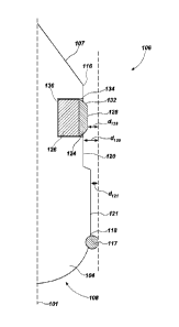
FIG. 2 is an enlarged side view of a gauge region of the drill bit of FIG 1;
FIG. 3 is a cross-sectional view of a portion of the gauge region of FIG. 2,
and
FIG. 4 is a graph illustrating the relationship between side cutting exhibited
by the drill
bit of FIG. 1 as a function of lateral force applied to the bit.
FIG. 5 is a graph illustrating the relationship between a volume of engagement
of the
drill bit of FIG. 1 as a function of bit tilt angle.
MODE(S) FOR CARRYING OUT THE INVENTION
The illustrations presented herein are not meant to be actual views of any
particular
cutting structure, drill bit, or component thereof, but are merely idealized
representations
which are employed to describe embodiments of the present disclosure. For
clarity in
description, various features and elements common among the embodiments may be
referenced with the same or similar reference numerals.
As used herein, directional terms, such as "above," "below," "up," "down,"
"upward,"
"downward," "top," "bottom," "upper," "lower," "top-most," "bottom-most," and
the like, are
to be interpreted relative to the earth-boring tool or a component thereof in
the orientation of
the figures.
As used herein, the terms "longitudinal," "longitudinally," "axial," or
"axially" refers
to a direction parallel to a longitudinal axis (e.g., rotational axis) of the
drill bit described
herein. For example, a "longitudinal dimension" or "axial dimension" is a
dimension
measured in a direction substantially parallel to the longitudinal axis of the
drill bit described
herein.
As used herein, the terms "radial" or "radially" refers to a direction
transverse to a
longitudinal axis of the drill bit described herein and, more particularly,
refers to a direction as
it relates to a radius of the drill bit described herein. For example, as
described in further
detail below, a "radial dimension" is a dimension measured in a direction
substantially
transverse (e.g., perpendicular) to the longitudinal axis of the drill bit as
described herein.
As used herein, the term "substantially" in reference to a given parameter,
property, or
condition means and includes to a degree that one of ordinary skill in the art
would understand
that the given parameter, property, or condition is met with a degree of
variance, such as
within acceptable manufacturing tolerances. By way of example, depending on
the particular
parameter, property, or condition that is substantially met, the parameter,
property, or
CA 03084341 2020-03-30
WO 2019/068000 PCT/US2018/053571
- 5 -
condition may be at least 90.0% met, at least 950% met, at least 99.0% met, or
even at least
99.9% met.
As used herein, the term "about" in reference to a given parameter is
inclusive of the
stated value and has the meaning dictated by the context (e.g., it includes
the degree of error
associated with measurement of the given parameter).
As used herein, the terms "comprising," "including," "containing,"
"characterized by,"
and grammatical equivalents thereof are inclusive or open-ended terms that do
not exclude
additional, unrecited elements or method steps, but also include the more
restrictive terms
"consisting of' and "consisting essentially of' and grammatical equivalents
thereof.
As used herein, the term "may" with respect to a material, structure, feature,
or method
act indicates that such is contemplated for use in implementation of an
embodiment of the
disclosure, and such term is used in preference to the more restrictive term
"is" so as to avoid
any implication that other compatible materials, structures, features and
methods usable in
combination therewith should or must be excluded.
As used herein, the term "configured" refers to a size, shape, material
composition,
and arrangement of one or more of at least one structure and at least one
apparatus facilitating
operation of one or more of the structure and the apparatus in a predetermined
way.
As used herein, the singular forms following "a," "an," and "the" are intended
to
include the plural forms as well, unless the context clearly indicates
otherwise.
As used herein, the telin "and/or" includes any and all combinations of one or
more of
the associated listed items.
As used herein, the term "earth-boring tool" means and includes any tool used
to
remove formation material and to form a bore (e.g., a borehole) through a
earth formation by
way of the removal of the formation material. Earth-boring tools include, for
example, rotary
drill bits (e.g., fixed-cutter or "drag" bits and roller cone or "rock" bits),
hybrid bits including
both fixed cutters and roller elements, coring bits, percussion bits, bi-
center bits, reamers
(including expandable reamers and fixed-wing reamers), and other so-called
"hole-opening"
tools.
As used herein, the term "cutting element" means and includes an element
separately
formed from and mounted to an earth-boring tool that is configured and
positioned on the
earth-boring tool to engage an earth (e.g., subterranean) formation to remove
formation
material therefrom during operation of the earth-boring tool to form or
enlarge a borehole in
CA 03084341 2020-03-30
WO 2019/068000 PCT/US2018/053571
- 6 -
the formation By way of non-limiting example, the term "cutting element"
includes tungsten
carbide inserts and inserts comprising superabrasive materials as described
herein.
As used herein, the term "superabrasive material" means and includes any
material
having a Knoop hardness value of about 3,000 Kgf/mm2 (29,420 MPa) or more such
as, but
not limited to, natural and synthetic diamond, cubic boron nitride and diamond-
like carbon
materials.
As used herein, the term "polycrystalline material" means and includes any
material
comprising a plurality of grains or crystals of the material that are bonded
directly together by
inter-granular bonds. The crystal structures of the individual grains of the
material may be
randomly oriented in space within the polycrystalline material.
As used herein, the term "polycrystalline compact" means and includes any
structure
comprising a polycrystalline material formed by a process that involves
application of
pressure (e.g., compaction) to the precursor material or materials used to
form the
polycrystalline material.
FIG. 1 is a perspective view of a drill bit 100 according to embodiments of
the
disclosure The drill bit 100 includes a bit body 102 having a longitudinal
axis 101 about
which the drill bit 100 rotates in operation. The bit body 102 comprises a
plurality of
blades 104 extending radially outward from the longitudinal axis 101 toward a
gauge
region 106 of the blade 104 and extending axially along the gauge region 106.
Outer
surfaces of the blades 104 may define at least a portion of a face region 108
and the gauge
region 106 of the drill bit 100.
The bit body 102 of the drill bit 100 is typically secured to a hardened steel
shank 111
having an American Petroleum Institute (API) thread connection for attaching
the drill bit 100
to a drill string. The drill string includes tubular pipe and equipment
segments coupled end to
end between the drill bit and other drilling equipment at the surface.
Equipment such as a
rotary table or top drive may be used for rotating the drill string and the
drill bit 100 within the
borehole. Alternatively, the shank 111 of the drill bit 100 may be coupled
directly to the drive
shaft of a down-hole motor, which then may be used to rotate the drill bit
100, alone or in
conjunction with a rotary table or top drive.
The bit body 102 of the drill bit 100 may be formed from steel. Alternatively,
the bit
body 102 may be formed from a particle-matrix composite material Such bit
bodies may be
formed by embedding a steel blank in a carbide particulate material volume,
such as particles
of tungsten carbide (WC), and infiltrating the particulate carbide material
with a liquefied
CA 03084341 2020-03-30
WO 2019/068000 PCT/US2018/053571
- 7 -
metal material (often referred to as a "binder" material), such as a copper
alloy, to provide a
bit body substantially formed from a particle-matrix composite material.
A row of cutting elements 110 may be mounted to each blade 104 of the drill
bit 100. For example, cutting element pockets may be formed in the blades 104,
and the
cutting elements 110 may be positioned in the cutting element pockets and
bonded (e.g.,
brazed, bonded, etc.) to the blades 104. The cutting elements 110 may
comprise, for
example, a polycrystalline compact in the form of a layer of hard
polycrystalline material,
referred to in the art as a polycrystalline table, that is provided on (e.g.,
formed on or
subsequently attached to) a supporting substrate with an interface
therebetween. In some
embodiments, the cutting elements 110 may comprise polycrystalline diamond
compact
(PDC) cutting elements each including a volume of superabrasive material, such
as
polycrystalline diamond material, supported on a ceramic-metal composite
material substrate.
Though the cutting elements 110 in the embodiment depicted in FIG. 1 are
cylindrical or disc-
shaped, the cutting elements 110 may have any desirable shape, such as a dome,
cone, chisel,
etc. In operation, the drill bit 100 may be rotated about the longitudinal
axis 101. As the
bit 100 is rotated under applied WOB, the cutting elements 110 may engage a
subterranean
formation mounted in the face 108 of the bit such that the cutting elements
110 exceed a
compressive strength of the subterranean formation and penetrate the formation
to remove
formation material therefrom in a shearing cutting action.
The gauge region 106 of each blade 104 may be an axially extending region of
each
blade 104. The gauge region 106 may be defined by a rotationally leading edge
112 opposite
a rotationally trailing edge 114 and an uphole edge 116 opposite a downhole
edge 118. The
uphole edge 116 is adjacent to a crown chamfer 107 of the bit 100 proximal to
a shank 111 of
the bit 100 and distal from the face region 108 of the bit 100. As used
herein, the terms
"downhole" and "uphole" refer to locations within the gauge region relative to
portions of the
drill bit 100 such as the face 108 of the bit 100 that engage the bottom of a
wellbore to remove
formation material. The uphole edge 116 is located closer to (e.g., proximate
to, adjacent to)
to the shank 111 of the bit 100 or to an associated drill string or bottom
hole assembly as
compared to the downhole edge 118 that is located closer to (e.g., proximate
to, adjacent to)
the face 108 of the bit 100.
The gauge region 106 may be divided (e.g., bisected) into a first and second
region
including an uphole region 120 and a downhole region 121, respectively. The
uphole
region 120 may be referred to herein as a "recessed region" as the uphole
region 120 is
CA 03084341 2020-03-30
WO 2019/068000
PCT/US2018/053571
- 8 -
radially recessed relative to the downhole region 121 of the gauge region 106,
which is
illustrated by a dashed line in FIG. 3, and relative to the outer diameter of
the bit 100. The
uphole region 120 may be located proximate to the uphole edge 116 of the gauge
region 106. In some embodiments, an outer surface of the blade 104 in the
recessed
region 120 may be recessed relative to an outer diameter of the bit body 102
by a radial
distance c/120 in a range extending from about 0.005 inch (0.127 mm) to about
0.100 inch
(2.54 mm). Accordingly, a diameter of the bit 100 is defined by the outer
surfaces of the
blade 104 in the recessed region 120 may be recessed relative to an outer
diameter of the
bit body 102 by a diametric distance in a range extending from about 0.010
inch (0.254
mm) to about 0.200 inch (5.08 mm). The downhole region 121 of the blade 104
may also
be recessed relative to the outer diameter of the bit body 102 by a radial
distance 61121 in a
range extending from about 0.005 inch (0.127 mm) to about 0.100 inch (0.254
mm).
Accordingly, substantially the entire gauge region 106 may be recessed
relative to the outer
diameter of the bit body 102.
At least one cutting element 122 may be mounted on the blade 104 in the gauge
region 106. As illustrated in FIG. 1, a single cutting element 122 may be
mounted on the
blade 104 such that a remainder of the gauge region 106 may be free of (e.g.,
devoid of)
cutting elements. The cutting element 122 may be mounted proximate to the
uphole
edge 116. In some embodiments, the cutting element 122 may be mounted within
an uphole
half of the gauge region 106. In other embodiments, the cutting element 122
may be mounted
within an upper quartile of the gauge region 106. By way of non-limiting
example, the cutting
element 122 may be mounted within about 1.000 inch (2.54 mm) or within about
0.500 inch
(12.7 mm) of the uphole edge 116 as measured from a center of the cutting
element 122.
Accordingly, the cutting element 122 may be mounted in the uphole region 120.
In some
embodiments, the cutting element 122 may be mounted in the front quartile of
the gauge
region 106. By way of non-limiting example, the cutting element 122 may be
mounted within
about 0.500 inch (12.7 mm) or within about 0.270 inch (6.858 mm) from the
rotationally
leading edge 112.
In other embodiments, as illustrated in FIG. 2, a plurality of cutting
elements 122
(e.g., two, three, or more) may be mounted on the blade 104. The cutting
elements 122 may
be mounted proximate to the uphole edge 116 such as within an uphole half of
the gauge
region 106 or an upper quartile of the gauge region 106. A remainder of the
gauge region 106
beyond the upper quartile of the gauge region 106 may be free of cutting
element. In such
CA 03084341 2020-03-30
WO 2019/068000 PCT/US2018/053571
- 9 -
embodiments, a first cutting element 122 may be located proximate (e.g.,
adjacent) to the
rotationally leading edge 112, and a second cutting element 122 may be located
proximate to
the rotationally trailing edge 114. By way of non-limiting example, the
cutting elements 122
may be mounted within about 0.500 inch (12.7 mm) or within about 0.270 inch
(6.858 mm)
.. from the respective rotationally leading edge 112 or trailing edge 114
proximate to which each
is located.
The cutting elements 122 may comprise a volume of superabrasive material 124,
such
as a diamond table, disposed on a substrate 126. The volume of superabrasive
material 124
may comprise a polycrystalline diamond (PCD) material, having a cutting face
128 defined
thereon. Additionally, an interface 130 may be defined between the substrate
126 and the
volume of superabrasive material 124. The substrate 126 may include a cemented
carbide
material, such as a cemented tungsten carbide material, in which tungsten
carbide particles
are cemented together in a metallic binder material. The metallic binder
material may
include, for example, cobalt, nickel, iron, or alloys and mixtures thereof.
The cutting
face 128 may be a substantially planar surface and may provide a substantially
blunt
surface in contact with the formation A diameter of the cutting element 122
may be selected
to extend in a range from about 0.39 inch (10 mm) to about 0.75 inch (19 mm)
and, more
particularly, may be about 0.43 inch (11 mm) or about 0.63 inch (16 mm).
In some embodiments, the volume of superabrasive material 124 may comprise at
least one chamfer surface. As illustrated in FIG. 3, the volume of
superabrasive
material 124 comprises a multi-chamfered edge. A first chamfer surface 132 may
be
provided at a radial periphery of the volume of superabrasive material 124
such as radially
about the cutting face 128. A second chamfer surface 134 may encircle (e.g.,
extend
radially outward relative to) the first chamfer surface 132.
In other embodiments, the cutting element 122 may comprise a sharp cutting
element,
or a cutting element lacking a chamfer surface about the cutting face 128. In
further
embodiments, the cutting element 122 may have one or more recesses formed in
the cutting
face such as described in U.S. Patent No. 9,482,057 issued to DiGiovanni et
al., entitled
"Cutting Elements for Earth-boring Tools, Earth-boring Tools Including Such
Cutting
Elements, and Related Methods," the disclosure of which is incorporated herein
in its entirety
by this reference. In yet other embodiments, the cutting element 122 may
comprise a dome-
shaped or hemispherical-shaped feature that is known in the art as an "ovoid."
CA 03084341 2020-03-30
WO 2019/068000 PCT/US2018/053571
- 10 -
As best illustrated in the cross-sectional view of FIG. 3, the cutting
elements 122
may be disposed in a pocket 136 formed in the blade 104 in the gauge region
106 The
cutting elements 122 may be mounted such that the substrate 126 is radially
recessed
relative to an outer surface of the blade 104 and enclosed within the pocket
136, and such
.. that at least a portion of the superabrasive material 124 extends radially
beyond the outer
surface of the blade 104. More particularly, the first chamfer surface 132
extends radially
beyond the outer surface of the blade 104, while the second chamfer surface
134 is radially
recessed relative to the outer surface of the blade 104.
The cutting element 122 may be mounted in the pocket 136 at a large back rake
range
such that the cutting face 128 may substantially face a sidewall of the
borehole in which the
drill bit 100 is rotated. In some embodiments, the cutting element 122 may be
mounted at a
back rake angle greater than 80 degrees such as within a range from about 85
degrees to about
90 degrees, from about 87 degrees to about 90 degrees, or at a back rake angle
of about 89
degrees.
The cutting element 122 may be mounted on the blade 104 in the gauge region
106
such that the cutting face 128 thereof is radially recessed relative to the
outer diameter of the
bit body 102. In some embodiments, the outer diameter of the drill bit 100 may
be defined by
a gage trimmer 117 mounted adjacent the downhole edge 118 of the gauge region
106. The
cutting face 128 may be recessed relative to the outer diameter of the drill
bit 100 by a radial
.. distance d128 in a range extending from about 0.005 inch (0.127 mm) to
about 0.100 inch
(0.254 mm), in a range extending from about 0.005 inch (0.127 mm) to about
0.050 inch (1.27
mm) and, more particularly, may be recessed by a distance of about 0.025 inch
(0.635 mm).
Accordingly, the cutting face 128 may be recessed relative to the outer
diameter of the drill
bit 100 by a diametric distance (e.g., twice the radial distance) in a range
extending from about
0.010 inch (0.254 mm) to about 0.200 inch (0.508 mm), in a range extending
from about
0.010 inch (0.254 mm) to about 0.100 inch (2.54 mm) and, more particularly,
may be recessed
by a distance of about 0.050 inch (1.27 mm). The cutting face 128 may extend
radially
beyond outer surfaces of the blade 104 in the uphole region 120 and/or the
downhole
region 121. In some embodiments, the cutting face 128 of the cutting element
122 may define
a radially outermost surface of the gauge region 106.
The drill bit 100 may be coupled to a drill string including a steerable
bottom hole
assembly configured to directionally drill a borehole. In some embodiments,
the steerable
bottom hole assembly may comprise positive displacement (Moineau) type motors
as well as
CA 03084341 2020-03-30
WO 2019/068000 PCT/US2018/053571
- 11 -
turbines have been employed in combination with deflection devices such as
bent housings,
bent subs, eccentric stabilizers, and combinations thereof to effect oriented,
nonlinear drilling
when the bit is rotated only by the motor drive shaft, and linear drilling
when the bit is rotated
by the superimposed rotation of the motor shaft and the drill string. In other
embodiments, the
steerable bottom hole assemblies may comprise a bent adjustable kick off (AKO)
sub.
FIG. 4 is a graph of a line 200 illustrating an amount of side cutting of the
drill
bit 100 as a function of increasing lateral force (e.g. force applied in a
direction
substantially transverse or perpendicular to the longitudinal axis 101)
applied to the bit 100
during operation thereof The ability of the drill bit 100 to cut the borehole
sidewall as
opposed to the bottom of the borehole is referred to in the art as "side
cutting." The amount of
walk or drift may depend on the rate at which the drill bit 100 side cuts the
borehole sidewall
relative to an intended side cutting rate. As illustrated in FIG. 4, at low
lateral forces, such
as lateral forces less than about 500 pounds (226.7 kilograms) depending at
least upon the
formation material and the compressive strength thereof and upon the size of
the bit 100,
the amount of side cutting exhibited by the bit 100 is minimal and relatively
constant.
Accordingly, this region 202 of the line 200 is referred to as the
"insensitive region" as the
bit 100 is minimally responsive to (e.g., insensitive to) minimal applications
of lateral
force. Such low lateral forces are generally unintentionally applied to the
drill bit 100
while the bit 100 is forming a straight portion of the borehole, such as a
vertical portion or
a horizontal (e.g., lateral) portion of the borehole. Side cutting while
drilling the straight
portion of the borehole may be substantially avoided as side cutting while
forming the
straight portion of the borehole leads to walk or drift of the bit 100 and
causes the borehole
to deviate from its intended path. Furthermore, side cutting while drilling
the straight
portion of the borehole may also lead to undesirable tortuosity, torque, and
drag problems,
which may lower the quality of the borehole and limit the length of the
straight portion
thereof that can be formed. Accordingly, the insensitivity of the drill bit
100 to low lateral
forces is desirable because limiting side cutting in the straight portion of
the borehole will
decrease the potential walk or drift of the bit 100 and improve the quality
and length of the
straight portions of the borehole.
While side cutting may be undesirable at low lateral forces when drilling the
straight portion of the borehole as previously described, side cutting may be
desirable at
greater side loads when drilling curved portions of the borehole. Such side
cutting enables
the bit 100 to directionally drill so as to form deviated or curved portions
of the borehole in
CA 03084341 2020-03-30
WO 2019/068000 PCT/US2018/053571
- 12 -
an efficient manner. Accordingly, at moderate lateral forces, such as lateral
forces greater
than 500 pounds (226.7 kilograms) and up to about 1500 pounds (680.2
kilograms)
depending at least upon the formation material and the compressive strength
thereof and upon
the size of the bit 100, the amount of side cutting exhibited by the gauge
region 106 of the
bit 100 begins to increase in a substantially constant, linear manner. This
region 204 of the
line 200 is referred to as the "linear region." At high lateral forces, such
as lateral forces
greater than about 1500 pounds (680.2 kilograms) depending at least upon the
formation
material and the compressive strength thereof and upon the size of the bit
100, the amount of
side cutting exhibited by the bit 100 is maximized and plateaus, or caps.
Accordingly, this
region 206 of the line 200 is referred to as the "cap region." In view of the
foregoing, the
gauge region 106 of the drill bit 100 may be shaped and topographically
configured such as by
recessing the gauge region 106 relative to the outer diameter of the bit 100
to limit side cutting
of the bit 100 while drilling a substantially straight portion of a borehole
without limiting side
cutting of the bit 100 while drilling a curved (e.g., deviated) portion of the
borehole. Overall,
as illustrated in FIG. 4, as the lateral force applied on the bit 100
increases, the cutting element
122 in the gauge region 106 of the bit 100 engages the subterranean formation
and
subsequently a remainder of outer surfaces of the blade 104 in the gauge
region 106 engage
the subterranean formation, the side cutting exhibited by the bit 100 may be
initially minimal
and substantially constant, may subsequently increase in a substantially
linear manner with
increasing lateral force, and may be subsequently maximized and substantially
constant.
Without being bound by any particular theory, the amount of side cutting
performed
by the gauge region 106 of the blade 104 may be at least partially a function
of the surface
area and/or volume of the gauge region 106 in contact with the formation
material at a
given lateral force. Therefore, according to embodiments of the present
disclosure, the drill
bit 100 and, more particularly, the gauge region 106 is designed and
topographically
configured to selectively control the surface area and/or volume of the gauge
region 106 in
contact with the sidewall of the borehole as a function of bit tilt angle of
the bit 100 and/or
lateral force applied to the bit 100. As used herein, the term "bit tilt
angle" refers to an angle
measured between the longitudinal axis 101 of the bit 100 and a borehole axis
extending
______________________________________________ centrally through the borehole.
As the drill bit 100 is operated to fol in the straight portion of
the borehole, the drill bit 100 is generally oriented such that the
longitudinal axis 101 of the
bit 100 is substantially coaxial with the borehole axis. The bit tilt angle of
the bit 100 may be
at least partially a function of the lateral force applied to the bit 100 such
that as the amount of
CA 03084341 2020-03-30
WO 2019/068000 PCT/US2018/053571
- 13 -
lateral force applied to the bit 100 increases, the bit tilt angle of the bit
100 increases
correspondingly. When the bit tilt angle is zero (e.g., when the longitudinal
axis 101 is
substantially coaxial with the borehole axis), the gauge region 106 and, more
particularly, the
cutting element 122 may not be in contact with the formation. When the bit
tilt angle is
.. greater than zero, at least a portion of the gauge region 106 and, more
particularly, the cutting
element 122 may come into contact with the borehole sidewall and remove
formation material
when sufficient lateral force is applied prior to a remainder of the gauge
region 106 contacting
the borehole sidewall. The gauge region 106 of bit 100 may be designed such
that the
anticipated surface area and/or volume of the gauge region 106 contacting the
formation at a
given lateral force and/or given bit tilt angle is selectively controlled
and/or tailored.
FIG. 5 is a graph of a line 300 illustrating a volume of the gauge region 106
in contact
with the formation material of the borehole sidewall as a function of
increasing bit tilt angle.
When lateral forces are applied to the bit 100 and the longitudinal axis 101
of the bit 100 is
inclined relative to the borehole axis, the cutting element 122 may contact
the formation
material of the borehole wall prior to the remainder of the gauge region 106
including outer
surfaces of the blade 104 in the uphole region 120 and the downhole region 121
Further, the
gauge region 106 is sized and configured such that as the bit tilt angle
increases with
application of low lateral forces as previously described herein, the volume
of the gauge
region 106 in contact with the formation, if any, remains minimal and
substantially constant.
.. As a result, the amount of side cutting performed by the gauge region 106
may be limited and
substantially constant over the range of low lateral forces as previously
described with regard
to the insensitive region of the line 200 of FIG. 4. Further, the size of the
insensitive region,
or the range of lateral forces over which the amount of side cutting is
minimal and relatively
constant, can be reduced or extended by tailoring the shape and topography of
the gauge
region 106 including the cutting element 122, the uphole region 120, and the
downhole
region 121. For instance, one or more of the distance by which the cutting
element 122 is
recessed relative to the outer diameter of the bit 100, the distance by which
the cutting
element 122 extends beyond the outer surface of the blade 104, the back rake
angle at which
the cutting element 122 is mounted, and one or more dimensions of the
superabrasive
.. material 124 of the cutting element 122 including, but not limited to, a
diameter of the cutting
element 122 and an angle at which the chamfers 132, 134 are formed may be
modified or
otherwise tailored to adjust the volume of the gauge region 106 that will
contact the sidewall
of the borehole.
CA 03084341 2020-03-30
WO 2019/068000 PCT/US2018/053571
- 14 -
At low lateral forces, such as forces less than about 500 pounds (226.7
kilograms)
depending at least upon the formation material and the compressive strength
thereof and upon
the size of the bit 100, the cutting element 122 may ride, rub on, or
otherwise engage the
borehole sidewall without substantially failing the formation material of the
sidewall (e.g.,
without exceeding the compressive strength of the foimation). In other words,
at low lateral
forces the cutting element 122 does not provide substantial side cutting
action.
As the bit tilt angle increases so as to steer or direct the drill bit 100
away from the
linear path of the substantially vertical portion of the borehole, the cutting
element 122 in the
gauge region 106 of the bit 100 may engage a borehole sidewall and penetrate
the formation
material thereof so as to remove formation material. As the bit tilt angle
increases, outer
surfaces of the blade 104 in the uphole region 120 and the downhole region 121
may
increasing engage the formation and increase the volume of the gauge region
106 in contact
with the formation material until the bit tilt angle is sufficiently high that
substantially all of
the volume of the gauge region 106 is in contact with the formation. Further,
as previously
described, the gauge region 106 of the bit 100 includes a recessed uphole
region 120. By
providing the recessed region at the top of the gauge region 106, the amount
of contact
between the gauge region 106 and the formation may be reduced, which enables
the bit 100 to
deviate from the vertical portion toward a substantially horizontal portion of
the borehole,
referred to as the "build up rate," over a shorter distance.
Accordingly, in operation, the drill bit 100 may exhibit the amount of side-
cutting
as a function of increasing lateral force and/or volume of the gauge region
106 engagement
as a function of bit tilt angle as previously described with reference to
FIGS. 4 and 5. By
configuring the gauge region 106 of the drill bit 100 such that the
anticipated volume of the
gauge region 106 contacting the formation at a given lateral force and/or
given bit tilt angle is
selectively controlled and/or tailored and particularly such that a low
lateral forces and small
bit tilt angles the gauge region 106 does not substantially engage the
formation material of the
borehole sidewall, the drill bit 100 exhibits a decreased potential to walk or
drift as the drill
bit 100 is used to directionally drill a borehole and may improve the quality
and length of
the straight portions of the borehole.
Additional non limiting example embodiments of the disclosure are described
below.
Embodiment 1: A drill bit for removing subterranean formation material in a
borehole
comprises a bit body comprising a longitudinal axis, at least one blade
extending radially
CA 03084341 2020-03-30
WO 2019/068000 PCT/US2018/053571
- 15 -
outward from the longitudinal axis along a face region of the bit body and
extending axially
along a gauge region of the bit body, and a single cutting element on the at
least one blade in
the gauge region. The cutting element is located proximate to an uphole edge
of the at least
one blade in the gauge region, and a remainder of the gauge region of the at
least one blade is
.. free of cutting elements mounted thereon.
Embodiment 2: The drill bit of Embodiment 1, wherein the cutting element is
mounted on the at least one blade at a back rake angle in a range extending
from about 85
degrees to about 90 degrees.
Embodiment 3: The drill bit of either of Embodiments 1 or 2, wherein the
cutting
element is radially recessed relative to an outer diameter of the drill bit.
Embodiment 4: The drill bit of any of Embodiments 1 through 3, wherein the
cutting
element is radially recessed relative to the outer diameter of the drill bit
by a distance in a
range from about 0.010 inch (0.254 mm) to about 0.100 inch (2.54 mm).
Embodiment 5: The drill bit of any of Embodiments 1 through 4, wherein the
cutting
element is radially recessed relative to the outer diameter of the drill bit
by a distance of about
0.025 inch (0.635 mm)
Embodiment 6: The drill bit of any of Embodiments 1 through 5, wherein the
cutting
element comprises a superabrasive table on a substrate, and wherein the
cutting element is
mounted on the at least one blade such that at least a portion of the
superabrasive table of the
cutting element extends radially beyond an outer surface of the at least one
blade in the gauge
region.
Embodiment 7: The drill bit of any of Embodiments 1 through 6, wherein the
superabrasive table comprises a chamfered edge, and wherein the chamfered edge
extends
radially beyond the outer surface of the at least one blade in the gauge
region.
Embodiment 8: The drill bit of any of Embodiments 1 through 7, wherein the
superabrasive table comprises multiple chamfered edges, and wherein one
chamfered edge of
the multiple chamfered edges extends radially beyond the outer surface of the
at least one
blade in the gauge region and at least one other chamfered edge of the
multiple chamfered
edges extends radially below the outer surface of the at least one blade in
the gauge region.
Embodiment 9: The drill bit of any of Embodiments 1 through 8, wherein at
least a
first portion of the blade in the gauge region is recessed relative to a
second portion of the at
least one blade in the gauge region, the first portion located uphole relative
to the second
CA 03084341 2020-03-30
WO 2019/068000 PCT/US2018/053571
- 16 -
portion, and wherein the cutting element is mounted in the first portion of
the at least one
blade.
Embodiment 10: The drill bit of any of Embodiments 1 through 9, wherein the
cutting
element is mounted adjacent a rotationally leading edge of the at least one
blade.
Embodiment 11: A directional drilling system comprising a steerable bottom
hole
assembly operably coupled to the drill bit of any of Embodiments 1 through 10.
Embodiment 12: A drill bit for removing subterranean formation material in a
borehole comprises a bit body comprising a longitudinal axis, at least one
blade extending
radially outward from the longitudinal axis along a face region of the bit
body and extending
axially along a gauge region of the bit body, and at least one cutting element
on the at least
one blade in the gauge region. The at least one cutting element is located in
an upper quartile
of the at least one blade in the gauge region such that a remainder of the
gauge region beyond
the upper quartile is free of cutting elements mounted thereon.
Embodiment 13: The drill bit of Embodiment 12, wherein the at least one
cutting
element is radially recessed relative to an outer diameter of the bit body.
Embodiment 14: The drill bit of either of Embodiments 12 or 13, wherein the at
least
one cutting element comprises a superabrasive table on a substrate, and
wherein the cutting
element is mounted on the at least one blade such that at least a portion of
the superabrasive
table of the cutting element extends radially beyond an outer surface of the
at least one blade
in the gauge region
Embodiment 15: The drill bit of any of Embodiments 12 through 14, wherein a
cutting face of the at least one cutting element extends radially beyond outer
surfaces of the
blade in the gauge region.
Embodiment 16: A method of drilling a borehole in a subterranean formation
comprises rotating a bit about a longitudinal axis thereof within the borehole
and engaging a
sidewall of the borehole with at least a portion of a gauge region of at least
one blade of the
bit. The gauge region comprises a cutting element on the at least one blade in
the gauge
region and located proximate to an uphole edge of the at least one blade in
the gauge region.
A remainder of the gauge region is free of cutting elements mounted thereon.
The method
further comprises increasing a tilt angle of the bit such that the cutting
element and the
remainder of the gauge region are consecutively engaged with the sidewall of
the borehole
with increasing tilt angle.
CA 03084341 2020-03-30
WO 2019/068000 PCT/US2018/053571
- 17 -
Embodiment 17. The method of Embodiment 16, wherein increasing the tilt angle
of
the bit comprises increasing a lateral force applied on the bit in a direction
substantially
perpendicular to the longitudinal axis such that the cutting element and the
remainder of the
gauge region consecutively engage the sidewall of the borehole and such that
side cutting
exhibited by the bit is initially minimal and substantially constant and
subsequently increases
in a substantially linear manner with increasing lateral force as an
increasing volume of the
cutting element engages the sidewall of the borehole.
Embodiment 18: The method of either of Embodiments 16 or 17, wherein
increasing
the lateral force applied on the bit such that side cutting exhibited by the
bit is initially
minimal and substantially constant comprises maintaining a substantially
constant volume of
the cutting element in contact with the sidewall of the borehole with
increasing applied lateral
force.
Embodiment 19: The method of any of Embodiments 16 through 18, wherein
increasing the lateral force applied on the bit such that side cutting
exhibited by the bit is
increased in a substantially linear manner with increasing lateral force
comprises increasing a
volume of the cutting element penetrating the sidewall of the borehole with
increasing applied
lateral force.
Embodiment 20 The method of any of Embodiments 16 through 19, further
comprising increasing a lateral force applied on the bit in a direction
substantially
perpendicular to the longitudinal axis such that side cutting exhibited by the
bit is
subsequently maximized and substantially constant after increasing side
cutting exhibited by
the bit in the substantially linear manner and such that substantially an
entire volume of the
gauge region engages the sidewall of the borehole.
While the disclosed structures and methods are susceptible to various
modifications
and alternative forms in implementation thereof, specific embodiments have
been shown by
way of example in the drawings and have been described in detail herein.
However, it should
be understood that the present disclosure is not limited to the particular
forms disclosed.
Rather, the present invention encompasses all modifications, combinations,
equivalents,
variations, and alternatives falling within the scope of the present
disclosure as defined by the
following appended claims and their legal equivalents.