Note: Descriptions are shown in the official language in which they were submitted.
CA 03084509 2020-05-19
WO 2019/129648
PCT/EP2018/086237
1
ELECTROSURGICAL ABLATION INSTRUMENT
FIELD OF THE INVENTION
The invention relates to an electrosurgical instrument
for delivering radiofrequency and microwave energy to
biological tissue in order to ablate the target tissue. In
particular, the probe is configured to be insertable through a
channel of a surgical scoping device or catheter that can be
introduced to a treatment site in a non-invasive manner. The
probe may be arranged to ablate tissue, such as a tumour, cyst
or other lesion. The probe may be particularly suited for
treatment in the pancreas.
BACKGROUND TO THE INVENTION
The application of heat energy to biological tissue is
well known as an effective method of killing cells. For
example, the application of radiofrequency or microwave energy
can heat and thus ablate (destroy) biological tissue. This
method may in particular be used for the treatment of cancer.
A technique of treating tissue in the pancreas using
endoscopic ultrasound guided radiofrequency ablation is known
(Pai, M., et al.: Endoscopic ultrasound guided radiofrequency
ablation, for pancreatic cystic neoplasms and neuroendocrine
tumors, World J Gastrointest Surg 2015 April 27; 7(4): 52-59).
In this technique a conductive wire having a small diameter
(e.g. 0.33 mm) is inserted through the working channel of an
ultrasound-enabled endoscope. RF power is applied to the wire
in conjunction with an external grounded return pad in contact
with the patient's skin to coagulate tissue in the liver and
pancreas. To ablate lesions it is necessary to apply power
for 90-120 seconds, and, in some cases to remove and
reposition the wire.
SUMMARY OF THE INVENTION
At its most general, the invention provides an
electrosurgical instrument having a microwave ablation antenna
dimensioned to be suitable for insertion into a pancreas via a
CA 03084509 2020-05-19
WO 2019/129648
PCT/EP2018/086237
2
surgical soaping device, to provide a rapid and accurate
alternative to known RF ablation techniques. Although the
invention may find particular use in the pancreas, it may also
be suitable for use in other awkward treatment sites, such as
the lungs, etc.
According to the invention, there is provided an
electrosurgical instrument comprising: a proximal portion
comprising a coaxial transmission line for conveying microwave
electromagnetic (EM) energy; a distal radiating portion; and
an intermediate impedance transformer arranged to match an
impedance of the coaxial transmission line to an impedance of
the distal radiating portion, wherein the distal radiating
portion comprises a microwave antenna for emitting the
microwave EM energy conveyed by the coaxial transmission line,
wherein the distal radiating portion has a maximum outer
diameter less than an outer diameter of the coaxial
transmission line. With these features, the instrument is
able to deliver microwave energy via a small diameter
structure.
The coaxial transmission line may comprise an inner
conductor separated from a proximal outer conductor by a first
dielectric material. The coaxial transmission line may be a
conventional coaxial cable. Advantageously, the inner
conductor of the coaxial cable may extend beyond a distal end
of the proximal outer conductor through the intermediate
impedance transformer and into the distal radiating portion.
In other words, the intermediate impedance transformer and the
distal radiating portion may shall a common coaxial cable.
This may be achieved by stripping away the outer conductor of
the coaxial transmission line along the a distal portion
thereof where the intermediate impedance transformer and the
distal radiating portion are to be formed. As discussed
below, the first dielectric material may also be used in the
intermediate impedance transformer and the distal radiating
portion. For example, the first dielectric can be selectively
removed in these regions to reduce its diameter. In some
cases it may be removed altogether and replaced with other
dielectric materials. Alternatively it may be used alone or
in combination with other materials.
The proximal outer conductor (i.e. the outer conductor of
the coaxial transmission line) may have an outer diameter
CA 03084509 2020-05-19
WO 2019/129648
PCT/EP2018/086237
3
equal to or less than 3 mm, preferably equal to or less than
2.2 mm. The maximum outer diameter of the distal radiating
portion may be equal to or less than 1 mm. The intermediate
impedance transformer may have a maximum outer diameter in
between that of the proximal outer conductor and the distal
radiating portion.
The intermediate impedance transformer is a quarter
wavelength coaxial transmission line. Here "quarter
wavelength" refers to the wavelength of the microwave energy
delivered by the coaxial transmission line. The instrument
may be designed for use at a particular frequency of microwave
energy, so this length is derivable for any given instrument.
In the quarter wavelength coaxial transmission line, the
inner conductor may be separated from an intermediate outer
conductor by a second dielectric material having a smaller
outer diameter than an outer diameter of the first dielectric
material. In one example, the second dielectric material is a
reduced diameter portion of the first dielectric material that
extends beyond the distal end of the proximal outer conductor.
Alternatively or additionally (in that the intermediate
impedance transformer may comprise a combination of dielectric
materials), the second dielectric material may include or
consist of a material having a higher relative permittivity
than the first dielectric material.
The inner conductor may extend through the distal
radiating portion to form a conductive portion of the
microwave antenna. In this example, the inner conductor of
the coaxial transmission line therefore extends along the
entire length of the instrument.
In another example, a distal conductive finger may be
mounted on a distal end of the inner conductor. The distal
conductive finger may form a conductive portion of the
microwave antenna. In this example, the inner conductor acts
as a feed for the microwave antenna. The distal radiating
portion may comprise a coaxial feed portion having the
microwave antenna formed at a distal end thereof.
The microwave antenna may be a loaded monopole antenna
having a distal dielectric material mounted over the
conductive portion of the microwave antenna. The distal
dielectric material may be a reduced diameter portion of the
first dielectric material that extends beyond the distal end
CA 03084509 2020-05-19
WO 2019/129648
PCT/EP2018/086237
4
of the proximal outer conductor. In this example, the first
dielectric material may extend along the entire length of the
instrument. Alternatively or additionally, the distal
dielectric material may comprise a rigid material having a
higher relative permittivity than the first dielectric
material. Ceramic or polyether ether ketone (PEEK) may be
used. The coaxial feed portion of the distal radiating
portion may use the same or a different dielectric material
from that which loads the microwave antenna.
A distal end of the microwave antenna may be sharpened to
facilitate insertion into tissue. Herein "sharpened" may mean
that the distal tip of the instrument tapers to a point, e.g.
in a needle-like manner. The sharpened portion may comprise
the dielectric material that loads the microwave antenna, or
may comprise a protruding portion of the distal conductive
finger in the case of an unloaded antenna.
In another example, the microwave antenna may be a
slotted antenna. For example, the distal radiating portion
may comprise a distal coaxial transmission line having a
distal inner conductor separated from a distal outer conductor
by a distal dielectric material. The slotted antenna may be
formed by removing portions of the distal outer conductor.
The removed portions may resemble windows in the distal outer
conductor through which the distal dielectric material is
exposed. There may be one or more windows along the length of
the microwave antenna. Each window may extend around the
whole circumference of the distal radiating portion. The
windows may be separated by a half wavelength of the microwave
energy emitted by the antenna.
The distal inner conductor may be electrically connected
to the distal outer conductor at a distal tip of the microwave
antenna. This may elongate the shape of the field emitted by
the antenna.
Also disclosed herein is an electrosurgical apparatus
comprising: a surgical scoping device having an instrument
cord configured to be insertable into a patient's body,
wherein the instrument cord has an instrument channel formed
therethrough; and an electrosurgical instrument according to
any preceding claim dimensioned to be insertable through the
instrument channel.
CA 03084509 2020-05-19
WO 2019/129648
PCT/EP2018/086237
The term "surgical soaping device" may be used herein to
mean any surgical device provided with an insertion tube that
is a rigid or flexible (e.g. steerable) conduit that is
introduced into a patient's body during an invasive procedure.
5 The insertion tube may include the instrument channel and an
optical channel (e.g. for transmitting light to illuminate
and/or capture images of a treatment site at the distal end of
the insertion tube. The instrument channel may have a
diameter suitable for receiving invasive surgical tools. The
diameter of the instrument channel may be 5 mm or less. In
embodiments of the invention, the surgical scoping device may
be an ultrasound-enabled endoscope.
Herein, the term "inner" means radially closer to the
centre (e.g. axis) of the instrument channel and/or coaxial
cable. The term "outer" means radially further from the centre
(axis) of the instrument channel and/or coaxial cable.
The term "conductive" is used herein to mean electrically
conductive, unless the context dictates otherwise.
Herein, the terms "proximal" and "distal" refer to the
ends of the elongate probe. In use the proximal end is closer
to a generator for providing the RF and/or microwave energy,
whereas the distal end is further from the generator.
In this specification "microwave" may be used broadly to
indicate a frequency range of 400 MHz to 100 GHz, but
preferably the range 1 GHz to 60 GHz. Specific frequencies
that have been considered are: 915 MHz, 2.45 GHz, 3.3 GHz, 5.8
GHz, 10 GHz, 14.5 GHz and 24 GHz. The device may delivery
energy at more than one of these microwave frequencies. In
contrast, this specification uses "radiofrequency" or "RF" to
indicate a frequency range that is at least three orders of
magnitude lower, e.g. up to 300 MHz, preferably 10 kHz to 1
MHz.
BRIEF DESCRIPTION OF THE DRAWINGS
Embodiments of the invention are discussed below with
reference to the accompanying drawings, in which:
Fig. 1 is a schematic diagram showing an electrosurgical
ablation apparatus that is an embodiment of the invention;
CA 03084509 2020-05-19
WO 2019/129648
PCT/EP2018/086237
6
Fig. 2 is a schematic sectional view through an
instrument cord of an endoscope that can be used with the
present invention;
Fig. 3 is a longitudinal cross-sectional view through an
ablation instrument that is an embodiment of the present
invention;
Fig. 4 is a longitudinal cross-sectional view through an
ablation instrument that is another embodiment of the present
invention;
Fig. 5 is a longitudinal cross-sectional view through an
ablation instrument that is another embodiment of the present
invention; and
Fig. 6 is a longitudinal cross-sectional view through an
ablation instrument that is another embodiment of the present
invention.
DETAILED DESCRIPTION; FURTHER OPTIONS AND PREFERENCES
Fig. 1 is a schematic diagram of an electrosurgical
ablation apparatus 100 that is capable of supplying microwave
energy and fluid, e.g. cooling fluid, to the distal end of an
invasive electrosurgical instrument. The system 100 comprises
a generator 102 for controllably supplying radiofrequency (RF)
and microwave energy. A suitable generator for this purpose
is described in WO 2012/076844, which is incorporated herein
by reference. The generator may be arranged to monitor
reflected signals received back from the instrument in order
to determine an appropriate power level for delivery. For
example, the generator may be arranged to calculate an
impedance seen at the distal end of the instrument in order to
determine an optimal delivery power level.
The generator 102 is connected to an interface joint 106
by an interface cable 104. The interface joint 106 is also
connected via a fluid flow line 107 to a fluid delivery device
108, such as a syringe,. In some examples, the apparatus may
be arranged, additionally or alternatively, to aspirate fluid
from the treatment site. In this scenario, the fluid flow
line 107 may convey fluid away from the interface joint 106 to
a suitable collector (not shown). The aspiration mechanism
may be connected at a proximal end of the fluid flow line 107.
CA 03084509 2020-05-19
WO 2019/129648
PCT/EP2018/086237
7
If needed, the interface joint 106 can house an
instrument control mechanism that is operable by sliding a
trigger, e.g. to control longitudinal (back and forth)
movement of one or more control wires or push rods (not
shown). If there is a plurality of control wires, there may
be multiple sliding triggers on the interface joint to provide
full control. The function of the interface joint 106 is to
combine the inputs from the generator 102, fluid delivery
device 108 and instrument control mechanism into a single
flexible shaft 112, which extends from the distal end of the
interface joint 106.
The flexible shaft 112 is insertable through the entire
length of an instrument (working) channel of a surgical
scoping device 114, which in embodiment of the present
invention may comprise an endoscopic ultrasound device.
The surgical scoping device 114 comprises a body 116
having a number of input ports and an output port from which
an instrument cord 120 extends. The instrument cord 120
comprises an outer jacket which surrounds a plurality of
lumens. The plurality of lumens convey various things from
the body 116 to a distal end of the instrument cord 120. One
of the plurality of lumens is the instrument channel discussed
above. Other lumens may include a channel for conveying
optical radiation, e.g. to provide illumination at the distal
end or to gather images from the distal end. The body 116 may
include a eye piece 122 for viewing the distal end.
An endoscopic ultrasound device typically provide an
ultrasound transducer on a distal tip of the instrument cord,
beyond an exit aperture of the instrument channel. Signals
from the ultrasound transducer may be conveyed by a suitable
cable 126 back along the instrument cord to a processor 124,
which can generate images in a known manner. The instrument
channel may be shaped within the instrument cord to direct an
instrument exiting the instrument channel through the field of
view of the ultrasound system, to provide information about
the location of the instrument at the target site.
The flexible shaft 112 has a distal assembly 118 (not
drawn to scale in Fig. 1) that is shaped to pass through the
instrument channel of the surgical scoping device 114 and
protrude (e.g. inside the patient) at the distal end of the
instrument cord.
CA 03084509 2020-05-19
WO 2019/129648
PCT/EP2018/086237
8
The structure of the distal assembly 118 discussed below
may be particularly designed for use with an endoscopic
ultrasound (EUS) device, whereby the maximum outer diameter of
the distal end assembly 118 is equal to or less than 2.0 mm,
e.g. less than 1.9 mm (and more preferably less than 1.5 mm)
and the length of the flexible shaft can be equal to or
greater than 1.2 m.
The body 116 includes a power input port 128 for
connecting to the flexible shaft 112. As explained below, a
proximal portion of the flexible shaft may comprise a
conventional coaxial cable capable of conveying the
radiofrequency and microwave energy from the generator 102 to
the distal assembly 118. Coaxial cables that are physically
capable of fitting down the instrument channel of an EUS
device are available with the following outer diameters: 1.19
mm (0.047"), 1.35 mm (0.053"), 1.40 mm (0.055"), 1.60 mm
(0.063"), 1.78 mm (0.070"). Custom-sized coaxial cables (i.e.
made to order) may also be used.
As discussed above, it is desirable to be able to control
the position of at least the distal end of the instrument cord
120. The body 116 may include a control actuator that is
mechanically coupled to the distal end of the instrument cord
120 by one or more control wires (not shown), which extend
through the instrument cord 120. The control wires may travel
within the instrument channel or within their own dedicated
channels. The control actuator may be a lever or rotatable
knob, or any other known catheter manipulation device. The
manipulation of the instrument cord 120 may be software-
assisted, e.g. using a virtual three-dimensional map assembled
from computer tomography (CT) images.
Fig. 2 is a view down the axis of the instrument cord
120. In this embodiment there are four lumens within the
instrument cord 120. The largest lumen is the instrument
channel 132. The other lumens comprise an ultrasound signal
channel 134 and an illumination channel 136, and a camera
channel 138 but the invention is not limited to this
configuration. For example, there may be other lumens, e.g.
for control wires or fluid delivery or suction.
In one embodiment, the invention may provide an
instrument that can perform tissue ablation at the distal end
of an EUS system catheter. In order for side effects to be
CA 03084509 2020-05-19
WO 2019/129648
PCT/EP2018/086237
9
reduced and the efficiency of the instrument to be maximised,
the transmitting antenna should be located as close to the
target tissue as possible. Ideally, the radiating part of the
instrument is located inside (e.g. at the centre of) the
tumour during treatment.
The invention may be particularly suited for treatment of
the pancreas. In order to reach the target site, the
instrument will need to be guided through the mouth, stomach
and duodenum. The instrument is arranged to access the
pancreas by passing through the wall of the duodenum. This
procedure places significant restrictions on the size of the
instrument that may pass into the pancreas. Conventionally,
instruments having an outer diameter no larger than 1 mm (e.g.
19 gauge) have been used.
The description below presents a number of antenna
configurations that are suitable for use in the distal
assembly 118 described.
In the following description, unless stated otherwise,
the length of a component refers to its dimension in the
direction parallel to the longitudinal axis of the coaxial
cable/instrument cord.
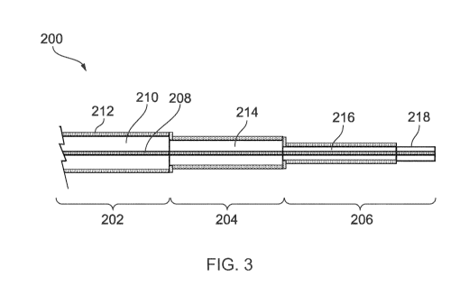
Fig. 3 is a cross-sectional view of the distal end of an
electrosurgical instrument 200 that is an embodiment of the
invention. Fig. 3 shows a distal end portion of the
instrument, which has three sections. A first section
comprises a coaxial cable 202 which extends to a proximal end
of the instrument, e.g. through the instrument channel of a
surgical scoping device as discussed above. The proximal end
of the coaxial cable 202 may be connected to an
electrosurgical generator to receive and convey microwave
energy, e.g. electromagnetic energy having a frequency of 5.8
GHz. A second section comprises an intermediate impedance
transformer 204. A third section comprises a distal radiating
portion 206. The intermediate impedance transformer 204 is
arranged to match the impedance of the coaxial cable 202 to
the impedance of the distal radiating portion 206.
The distal radiating portion 206 is dimensioned to be
suitable for treating tissue in the pancreas. In particular
its dimensions are similar to known probes that are used to
penetrate into the pancreas through the wall of the duodenum,
e.g. using an EUS device. A maximum outer diameter of the
CA 03084509 2020-05-19
WO 2019/129648
PCT/EP2018/086237
distal radiating portion 206 may thus be equal to or less than
1 mm (e.g. equal to or less than a 19 gauge needle). The
length of the distal radiating portion may be around 40 mm.
The coaxial cable 202 may be a conventional flexible
5 coaxial microwave cable having an outer diameter selected to
enable it to pass through the instrument channel of a surgical
scoping device. In one example, the outer diameter of the
coaxial cable 202 may be equal to or less than 2.2 mm. For
example, a SucoformO 86 cable may be used. The coaxial cable
10 comprises an inner conductor 208 that is separated from an
outer conductor 212 by a insulating dielectric material 210.
A protective jacket (not shown) may be provided around the
outer surface of the outer conductor 212. The length of the
coaxial cable 202 may be 1.2 m or more. Only a distal portion
thereof is shown in Fig. 3.
In this embodiment, the inner conductor 208 of the
coaxial cable 202 extends beyond the distal end of the outer
conductor 212 through both the intermediate impedance
transformer 204 and the distal radiating portion 206. All
three sections of the distal end assembly therefore share a
common inner conductor. In fact, in one example, the
intermediate impedance transformer 204 and the distal
radiating portion 206 may be formed by stripping the outer
conductor from distal sections of the coaxial cable,
selectively removing part of the dielectric material 210 to
achieve a desired dielectric outer diameter for each portion,
and then providing a new outer conductor over the reduced
diameter portions. The intermediate impedance transformer 204
has a dielectric material 214 having a first reduced diameter,
while the distal radiating portion 206 has a dielectric
material 216 having a second reduced diameter. The first
reduced diameter is less than the diameter of the dielectric
material 210 in the coaxial cable 202. The second reduced
diameter is less than the first reduced diameter. The
relationship between the diameters is discussed in more detail
below.
In this embodiment, the distal radiating portion 206
comprises a loaded monopolar antenna 218, which may be
provided by removing the outer conductor from a distalmost
length of the distal radiating portion 206. The loaded
monopolar antenna 218 may have a length equal to an odd
CA 03084509 2020-05-19
WO 2019/129648
PCT/EP2018/086237
11
multiple of a quarter wavelength of the microwave energy
conveyed by the coaxial cable 202.
As discussed above, it is desirable for the maximum outer
diameter of the distal radiating portion 206 (which is the
portion to be inserted into the pancreas) to be equal to or
less than 1 mm. In one example, this is achieved by the
following transverse dimensions for the relevant components:
Component Outer diameter (mm) Material
Inner conductor 0.53 (d1)
Cu/Ag plated steel
Dielectric 0.85 (d2) PTFE
Outer conductor 1.00 Cu
Table 1: Dimensions for distal radiating portion 206
The thickness of the outer conductor in this example
would be 0.075 mm. The relative permittivity Er of the
dielectric material used in this example is 1.85, which
provides an impedance Zõt for the distal radiating portion as
follows:
138
Zout = logo
(¨ id2) = man
vEr d
Accordingly, given that the impedance Zm of the coaxial
cable 202 is son, the impedance Zt of the intermediate
impedance transformer 204 is calculated as
Zt= \IZinZout = 32.25n
Since in this example the same inner conductor and same
dielectric material are used in the intermediate impedance
transformer 204, the outer diameter d3 of the dielectric
material 214 can be calculated to satisfy the relation:
138
(¨d3) = 32.25,0,
VEr di
CA 03084509 2020-05-19
WO 2019/129648
PCT/EP2018/086237
12
Solving this gives d3 as 1.1 mm. Following this, the
transverse dimensions for the relevant components in the
intermediate impedance transformer 204 may be as follows:
Component Outer diameter (mm) Material
Inner conductor 0.53 (d1) Cu/Ag plated steel
Dielectric 1.1 (d3) PTFE
Outer conductor 1.5 Cu
Table 2: Dimensions for intermediate impedance transformer 204
The length of the intermediate impedance transformer 204
is preferably an odd multiple quarter wavelength of the
microwave energy conveyed therein. Where Er is 1.85 mm, a
quarter wavelength at 5.8 GHz is 9.5 mm.
If the same dielectric material is used for the whole
length of the instrument, the length of the loaded monopolar
antenna 218 may also be 9.5 mm. However, the same dielectric
material need not be used everywhere. For example, a
different dielectric material may be used for loaded monopolar
antenna 218. For example, the length of the loaded monopolar
antenna 218 may be reduced by using a dielectric material
having a higher relative permittivity. In one example, a
rigid dielectric material such as ceramic or polyether ether
ketone (PEEK) could be used. In other example, the distal
radiating portion 206 may comprise an unloaded antenna, e.g. a
comprising a portion of exposed inner conductor. An example
of this kind of structure is discussed with reference to Fig.
5 below.
The instrument 200 discussed above provides a means of
introducing microwave energy into a pancreas that can
facilitate more accurate and effective treatment than the
radiofrequency-based techniques that have been used
heretofore. In particular, the transport mechanism by which
energy is delivered into device from a microwave antenna is
primarily radiation. The target area is thus rapidly treated,
and the risk of energy leakage or concentration in unwanted
area is reduced. This may be in contrast to RF-based
techniques in which the transport mechanism is primarily by
CA 03084509 2020-05-19
WO 2019/129648
PCT/EP2018/086237
13
conduction, and where the use of an externally positioned
return pad can make the location of current paths difficult to
control.
Although the instrument disclosed herein may be
particularly suitable for use with microwave energy, the
instrument may also provide a bipolar structure for delivering
radiofrequency (RF) energy. In one example, the same
structure that forms an antenna for radiating microwave energy
provides an active electrode and a return electrode suitable
for delivering RF energy therebetween. The active electrode
may be the inner conductor. The return electrode may be a
distal portion of the outer conductor. This arrangement
provides a localised return path for the RF current, and hence
may be preferable to the prior art instruments that require a
separate external return pad. In other examples, the
instrument may comprise a separate structure for delivering RF
energy.
As discussed above, the instrument may be connectable to
a generator that can deliver both RF and microwave energy
separately or simultaneously along a coaxial transmission
line. Accordingly, the instrument may be selectively operable
in a plurality of treatment modes, e.g. comprising any one,
two, three or more of: (i) microwave only, (ii) RF only, (iii)
RF followed by microwave, (iv) microwave followed by RF, (v)
RF and microwave simultaneously. The instrument is thus
capable of performing treatment under more sophisticated
energy application regimes that conventional RF ablation
devices.
Fig. 4 is a cross-sectional view of the distal end of an
electrosurgical instrument 240 that is another embodiment of
the invention. Features in common with the embodiment shown
in Fig. 3 are given the same reference numbers and are not
discussed again. Similar to Fig. 3, the instrument 240
utilises a common inner conductor from the coaxial cable 202
through the intermediate impedance transformer 204 and distal
radiating portion 206. However, in this embodiment, the
dielectric material of the coaxial cable 202 may be completely
removed and replaced with alternative materials in the
intermediate impedance transformer 204 and distal radiating
portion 206.
CA 03084509 2020-05-19
WO 2019/129648
PCT/EP2018/086237
14
It may be desirable for the distal parts of the
instrument to be rigid in order to assist in pushing the
instrument insider tumours to be treated. Accordingly, the
intermediate impedance transformer 204 and distal radiating
portion 206 may each be provided with a rigid dielectric
material 242, 244. The rigid dielectric materials 242, 244 in
this sections may be the same or different. For example, the
intermediate impedance transformer 204 may have a dielectric
material 242 formed form PEEK, whereas the distal radiating
portion 206 may have a dielectric material 244 formed from
ceramic, or vice versa. As explained above, an advantage of
these materials is that they have a higher relative
permittivity than the dielectric material 210 of the coaxial
cable 202, which enables the distal portion to be compact.
The rigid dielectric materials 242, 244 may be moulded around
or otherwise mounted on the inner conductor 208 after the
dielectric material 210 is stripped therefrom. As discussed
above, a new outer conductor is applied over the intermediate
impedance transformer 204 and relevant parts of the distal
radiating portion 206 after the rigid dielectric materials
242, 244 are in place.
In a particular example having the structure shown in
Fig. 4, the intermediate dielectric material 242 and distal
dielectric material are both PEEK. The distal radiating
portion 206 has a total length of 3 cm. The outer
metallisation 244 extends over 2 cm of the total length, to
leave a distalmost 1 cm portion of exposed PEEK (with the
inner conductor running within). The outer metallisation 244
has an inner diameter of 0.8 mm and an outer diameter of 1.0
mm.
Fig. 5 is a cross-sectional view of the distal end of an
electrosurgical instrument 260 that is another embodiment of
the invention. Features in common with the embodiment shown
in Fig. 3 are given the same reference numbers and are not
discussed again. In this example, the inner conductor 208
from the coaxial cable 202 extends through the intermediate
impedance transformer 204 and terminates at a proximal end of
the distal radiating portion 206. A rigid conductive finger
266 is mounted on an electrically connected to a distal end of
the inner conductor 208. In this example, the rigid
conductive finger 266 formed the inner conductor of the distal
CA 03084509 2020-05-19
WO 2019/129648
PCT/EP2018/086237
radiating portion 206 and protrudes therefrom as an unloaded
monopole antenna 268. The protruding portion is sharpened,
e.g. to resemble a needle, to facilitate insertion into
tissue. The rigid conductive finger 266 may be made from
5 stainless steel or the like.
In this example, the dielectric materials 262, 264 used
in the intermediate impedance transformer 204 and the distal
radiating portion 206 are different from the dielectric
material 210 of the coaxial cable 202. As discussed above
10 with reference to Fig. 4, these material may be chosen to
impart desired physical properties (e.g. rigidity) or to
control the length of the respective portion of the
instrument. In the example shown, the outer diameter of the
rigid conductive finger 266 may be greater than the outer
15 diameter of the inner conductor 208, which will have an effect
on the impedance of the distal portion.
The electrosurgical instrument 260 further comprises a
retractable sheath 270 mounted over the coaxial cable 202.
The sheath 270 is for controlling the depth of insertion and
for protecting the lining of the instrument channel against
damage due to the sharp tip of the antenna. The sheath 270
may extend over a distal portion of the instrument. It may
have a calibrated scale (e.g. 1 mm to 30 mm), so that as the
sheath is drawn back, the antenna is exposed. A distal end
272 of the sheath may be located against the wall of the
duodenum whilst the antenna is inserted through the wall into
the pancreas. The sheath end may thus act as a stop or
reference point. The sheath may have an outer diameter sized
to fit within the instrument channel. For example, it may be
2.4 mm or 2.7mm. Although only illustrated in Fig. 5, it is
to be understood that the sheath 270 may be used with any of
the embodiments disclosed herein.
Fig. 6 is a cross-sectional view of the distal end of an
electrosurgical instrument 280 that is another embodiment of
the invention. Features in common with the embodiment shown
in Fig. 3 are given the same reference numbers and are not
discussed again. In this example, the distal radiating
portion 206 comprises a slotted antenna structure 286.
Similar to Fig. 3, the instrument 280 utilises a common inner
conductor from the coaxial cable 202 through the intermediate
impedance transformer 204 and distal radiating portion 206.
CA 03084509 2020-05-19
WO 2019/129648
PCT/EP2018/086237
16
In this embodiment, the dielectric material of the coaxial
cable 202 may be completely removed and replaced with
alternative materials in the intermediate impedance
transformer 204 and distal radiating portion 206. The
intermediate impedance transformer 204 has a intermediate
dielectric material 282 and the distal radiating portion 206
has a distal dielectric material 284. The intermediate
dielectric material 282 and the distal dielectric material 284
may be the same or different. They may both differ from the
dielectric material 210 of the coaxial cable.
To provide a compact slotted antenna, is may be desirable
for the distal dielectric material 284 provide a high load to
the structure, e.g. by having a dielectric constant equal to
or greater than 20, preferably equal to or greater than 40.
The slotted antenna 286 is formed by creating one or more
windows or slots 288 in an outer conductive layer on the
distal radiating portion 206. Where a plurality of slots are
formed, there are separated along the length of the distal
radiating portion 206 by half a wavelength of the microwave
energy conveyed by the distal radiating portion 206. In order
to create an elongated, i.e. forward directed, ablation field,
a distal end of the inner conductor 208 may be electrically
connected to the outer conductive layer on the distal
radiating portion 206, e.g. via a conductive end cap 290. The
distalmost slot on the distal radiating portion 206 is
preferably spaced from the distal end (e.g. the end cap 290)
by a quarter wavelength of the microwave energy conveyed by
the distal radiating portion 206. In one example, the
dielectric material 284 may have a relative permittivity of
49, whereby the quarter wavelength for microwave energy having
a frequency of 5.8 GHz is 1.85 mm. In this example, the slots
are spaced at 3.7 mm intervals along the length of the distal
radiating portion 206.
In use, the instrument according to any of the examples
set out above may be inserting through the instrument channel
of an surgical scoping device to reach a treatment site, e.g.
through the wall of the duodenum into the pancreas. The
distal radiating portion 206 may penetrate tissue so that
microwave energy delivered by the coaxial cable 202 is
radiating into the tissue to ablate it.
CA 03084509 2020-05-19
WO 2019/129648
PCT/EP2018/086237
17
In some procedures, an aspiration needle may be inserted
to the treatment site before the instrument, e.g. to remove
fluid from a cyst or the like.
The instrument of the invention may find particular use
as an alternative to known RF ablation techniques, especially
because the size of the instrument is of the same order as
known RF probes, and can therefore be introduced using the
same equipment.