Note: Descriptions are shown in the official language in which they were submitted.
CA 03084762 2020-06-04
WO 2019/117853 PCT/US2017/065590
METHODS FOR PRODUCING FLEXIBLE ULTRAVIOLET LIGHT GENERATION SHEETS
AND SYSTEMS
TECHNICAL FIELD
[0001] The present invention relates generally to ultraviolet (UV) light
generating sheets and
systems, and methods for making such sheets and systems. More specifically,
but not by way
of limitation, the following describes devices generating UV light and for
treating, e.g.,
disinfecting, fluids or materials by exposing the fluids or materials to UV
light.
BACKGROUND
[0002] Exposure to UV light, corresponding to electromagnetic radiation with
wavelengths of
between about 100 nm and about 400 nm, is known to induce degradation to many
materials,
including biological materials. UV light can break down DNA so that a cell
cannot reproduce
and can also degrade toxins, making UV light useful for disinfection or
purification purposes.
The use of UV light to kill pathogens, such as microorganisms, has found
applications in
disinfecting air, water, food, beverages, and blood components. UV
disinfection has many
advantages over alternative methods, such as chlorine-based disinfection. For
example, UV
exposure does not introduce toxins or residues into the process and may not
alter the
chemical composition, functionality, taste, odor, or pH of the product.
[0003] Traditional sources of UV light include mercury or xenon arc lamps.
Mercury lamps,
for example, may generate UV light with wavelengths of 253.7 nm and 185 nm.
More
recently, UV light emitting diodes (LEDs) have been developed that offer the
advantages of
reduced power consumption, reduced size, longer lifetime, and instant turn on
as compared to
traditional mercury or xenon lamp sources. UV-LEDs may generate UV light with
wavelengths
from 200 nm to 400 nm, for example.
[0004] A typical UV treatment system includes an inlet port, a treatment
chamber in which
air or water flows through the chamber, a UV light source that emits radiation
that impinges
the volume of the treatment chamber, and an exit port. Due to their small
size, however,
toxins and pathogens can be shielded from UV light exposure, so improved UV
light treatment
systems and methods are useful.
[0005] U.S. Patent 9,409,797 discloses a device for treating a medium using UV
radiation
including a treatment chamber to accommodate the medium. An LED UV radiation
source
provides UV radiation. A chamber-forming structure has a stiffening base
structure with at
least one orifice formed therein and has a UV-radiation-transmissive film. The
base structure
defines a placement of the UV-radiation transmissive film. The chamber-forming
structure
1
CA 03084762 2020-06-04
WO 2019/117853 PCT/1JS2017/065590
separates the treatment chamber from the LED UV radiation source, and the UV
radiation is
introduced into the treatment chamber through the chamber-forming structure.
[0006] U.S. Patent 9,586,838 discloses an LED-based system for purifying a
fluid flowing
through a pipe, comprising means for mounting the system on the pipe, a
housing, a pliant
carrier structure comprising a plurality of LEDs arranged flush with a first
surface of the
structure and configured to emit radiation in the UV range, wherein when the
system is pipe-
mounted, the structure is detachably arranged within the housing, and the
structure adopts a
substantially tubular shape within the housing with the first surface
delimiting a purifying
chamber, wherein the purifying chamber is in fluid communication with the pipe
so that the
fluid flowing through the pipe passes, prior to being dispensed, through the
purifying chamber
where it is exposed to UV radiation of the energized LEDs.
[0007] U.S. Publication 2017/0281812 describes approaches for treating a fluid
transport
conduit with ultraviolet radiation. A light guiding unit, operatively coupled
to a set of ultraviolet
radiation sources, encloses the fluid transport conduit. The light guiding
unit directs ultraviolet
radiation emitted from the ultraviolet radiation sources to ultraviolet
transparent sections on an
outer surface of the fluid transport conduit. The emitted ultraviolet
radiation passes through
the ultraviolet transparent sections, penetrates the fluid transport conduit
and irradiates the
internal walls. A control unit adjusts a set of operating parameters of the
ultraviolet radiation
sources as a function of the removal of contaminants from the internal walls
of the fluid
transport conduit.
[0008] There continues to be a need for improved UV treatment systems.
SUMMARY
[0009] In the embodiments described herein, the present invention provides
treatment,
disinfection, or purification sheets and systems employing ultraviolet (UV)
light emitting diodes
and one or more UV active materials, such as UV reflective materials, UV
scattering materials,
and UV transparent materials, and methods of making UV light generation sheets
and
systems.
[0010] Disclosed UV light generation systems (also referred to as UV treatment
systems
and UV emitting systems) include those comprising flexible circuits featuring
multiple UV-
LEDs and, and other UV active layers, such as UV diffuse reflective layers or
UV transmitting
scattering layers. The UV light generation systems may also further include
additional
overlayers or underlayers, such as a supporting layer, a UV transparent
overlayer, or a UV
transparent encapsulating layer. The disclosed UV light generation systems may
be
2
CA 03084762 2020-06-04
WO 2019/117853 PCT/1JS2017/065590
submersed in a fluid, such as a liquid or a gas, and used to treat the
material of the fluid or
other materials suspended in the fluid, such as particles or objects, by
exposure to UV light.
The disclosed UV light generation systems may be flexible, allowing for their
arrangement into
enclosing configurations, such as configurations enclosing a fluid pathway.
Optionally, the
disclosed UV light generation systems may feature wrapped configurations. For
example, a
UV light generation sheet may be arranged in a helically wrapped configuration
around a fluid
path to allow for treatment of fluid in the fluid path by exposure to UV
light. Alternatively, UV
diffuse reflective layers may be wrapped helically with gaps between
longitudinal sides to
allow for UV-LEDs to be positioned at the gaps.
[0011] UV diffuse reflective or UV transmitting scattering layers of the UV
light generation
systems may advantageously allow the transmitted UV light to form an uniform
UV light
distribution, which may allow for more effective treatment and exposure to UV
light, minimizing
dim or unexposed areas in a treatment region. The UV diffuse reflective or UV
transmitting
scattering layers may only minimally absorb UV light, allowing for high UV
intensities to be
generated with dispersal of the light due to the diffuse reflective or
scattering nature of the
layers. The UV light generation system may also include photocatalysts, such
as metal
oxides photocatalysts including titanium dioxide, on the surface of the
overlayer that is
exposed to the fluid medium. The use of photocatalysts that generate reactive
oxygen
species upon absorbing UV light can be very effective in killing, destroying,
or degrading
pathogens.
[0012] Methods of making UV light generation systems include wrapping UV
diffuse
reflective layers around a mandrel such that a gap is present between
adjacent, e.g., nearby,
longitudinal sides of the UV diffuse reflective layer and positioning a
flexible circuit adjacent to
the UV diffuse reflective layer to align multiple UV-LEDs of a flexible
circuit at the gap. A
second UV diffuse reflective layer may be wrapped around the mandrel and first
diffuse
reflective layer, such as in an opposite rotation direction, with a second gap
that overlaps the
first gap at multiple locations corresponding to a plurality of openings. The
method can further
comprising positioning a flexible circuit including multiple UV-light emitting
diodes (UV-LEDs)
adjacent, e.g., adjoining, to the first or second UV diffuse reflective layer,
wherein the
positioning of the flexible circuit includes aligning the multiple UV-LEDs to
correspond to the
first gap or the openings when the second UV diffuse reflective layer is used.
The UV-LEDs of
the flexible circuit may be aligned at the openings to allow light generated
by the UV-LEDs to
3
CA 03084762 2020-06-04
WO 2019/117853 PCT/1JS2017/065590
pass through the openings. The first UV diffuse reflective layer may be
wrapped around an
overlayer, e.g., an overlayer comprising a photocatalysts, such as titanium
dioxide (TiO2).
[0013] In one embodiment, there is provided a method of making an ultraviolet
(UV) light
generation system, the method comprising wrapping a first UV diffuse
reflective layer in a first
direction around a mandrel with a first gap between adjacent, e.g., nearby,
longitudinal sides
of the first UV diffuse reflective layer, wherein the first UV diffuse
reflective layer is flexible,
and positioning a flexible circuit including multiple UV-light emitting diodes
(UV-LEDs)
adjacent, e.g. adjoining, to the first UV diffuse reflective layer, wherein
the positioning of the
flexible circuit includes aligning the multiple UV-LEDs to correspond to the
first gap. The
flexible circuit may be aligned with the multiple UV-LEDs to correspond to the
first gap. Each
of the multiple UV-LEDs is positioned to direct generated UV light through the
first gap.
[0014] In another embodiment, there is provided a method of making an
ultraviolet (UV)
light generation system, the method comprising wrapping a first UV diffuse
reflective layer in a
first direction around a mandrel with a first gap between adjacent
longitudinal sides of the first
UV diffuse reflective layer, wherein the first UV diffuse reflective layer is
flexible, wrapping a
second UV diffuse reflective layer in a second direction around the mandrel
and the first UV
diffuse reflective layer with a second gap between adjacent longitudinal sides
of the second
UV diffuse reflective layer, wherein the second UV diffuse reflective layer is
flexible, and
wherein a portion of the first gap and a portion of the second gap overlap to
generate a
plurality of openings, positioning a flexible circuit including multiple UV-
light emitting diodes
(UV-LEDs) adjacent to the second UV diffuse reflective layer, wherein the
positioning of the
flexible circuit includes aligning the multiple UV-LEDs to correspond to the
plurality openings.
Each of the multiple UV-LEDs is positioned to direct generated UV light
through the openings.
[0015] Other methods of making UV light generation system, such as a UV light
generation
sheet, are disclosed, Such methods may comprise generating a plurality of
openings in a UV
diffuse reflective layer and positioning a flexible circuit adjacent to the UV
diffuse reflective
layer such that multiple UV-LEDs of the flexible circuit are aligned at the
openings.
[0016] While multiple embodiments are disclosed, still other embodiments of
the present
invention will become apparent to those skilled in the art from the following
detailed
description, which shows and describes illustrative embodiments of the
invention.
Accordingly, the drawings and detailed description are to be regarded as
illustrative in nature
and not restrictive.
4
CA 03084762 2020-06-04
WO 2019/117853 PCT/1JS2017/065590
BRIEF DESCRIPTION OF THE DRAWINGS
[0017] FIG. 1 provides a schematic illustration showing a cross-section of a
flexible UV light
generation sheet in accordance with some embodiments.
[0018] FIG. 2A and FIG. 2B provide schematic illustrations showing cross-
section side and
overhead views of flexible UV light generation sheets in accordance with some
embodiments.
[0019] FIG. 3A and FIG. 3B provide schematic illustrations showing cross-
sections of
flexible UV light generation sheets in accordance with some embodiments.
[0020] FIG. 4 provides a schematic illustration showing a cross-section of a
flexible UV light
generation sheet in accordance with some embodiments.
[0021] FIG. 5 provides a schematic illustration showing a cross-section of a
flexible UV light
generation sheet in accordance with some embodiments.
[0022] FIG. 6 provides a schematic illustration showing a cross-section of a
flexible UV light
generation sheet in accordance with some embodiments.
[0023] FIG. 7A and FIG. 7B provide schematic illustrations showing cross-
sections of
flexible UV light generation sheets in accordance with some embodiments.
[0024] FIG. 8A and FIG. 8B provides a schematic illustration showing a
flexible UV light
generation sheet arranged in a helical wrapped configuration in accordance
with some
embodiments.
[0025] FIG. 8C provides a schematic illustration showing a flexible UV light
generation sheet
arranged in a longitudinal wrapped configuration in accordance with some
embodiments.
[0026] FIG. 9A and FIG. 9B provide a schematic illustrations showing cross-
sectional views
of UV treatment systems in accordance with some embodiments.
[0027] FIG. 10 provides a schematic illustration showing a cross-sectional
view of a UV
treatment system in accordance with some embodiments.
[0028] FIG. 11 provides a schematic illustration showing a cross-sectional
view of a UV
treatment system in accordance with some embodiments.
[0029] FIG. 12 provides a schematic illustration showing a cross-sectional
view of a UV
treatment system in accordance with some embodiments.
[0030] FIG. 13A and FIG. 13B provides schematic illustrations showing cross-
sectional and
side views of a UV treatment system in accordance with some embodiments.
[0031] FIG. 14 provides an example circuit for driving LEDs in a series
configuration.
[0032] FIG. 15 provides an example circuit for driving LEDs in a parallel
configuration.
CA 03084762 2020-06-04
WO 2019/117853 PCT/1JS2017/065590
[0033] FIG. 16 provides an example circuit for driving LEDs and monitoring UV
light output
using a UV sensitive photodetector.
[0034] FIGs. 17A-17F provide schematic illustrations (front (1), side (2), and
top(3)) detailing
a method of making a UV light generation system in accordance with some
embodiments.
[0035] FIG. 18 provides a plot showing total reflectivity of a UV diffuse
reflective layer as a
function of wavelength.
[0036] FIG. 19 provides a plot showing total transmission of different
materials as a function
of wavelength.
[0037] FIG. 20 provides a plot showing haze percent of different materials as
a function of
wavelength.
[0038] FIG. 21 provides an overview of an example method of making a UV light
generation
system in accordance with some embodiments.
[0039] FIG. 22 provides an overview of an example method of making a UV light
generation
system in accordance with some embodiments.
[0040] FIG. 23 provides an overview of an example method of making a UV light
generation
system in accordance with some embodiments.
[0041] FIGs. 24A-24F provide schematic illustrations of methods of making a UV
light
generation system using one UV diffuse reflective layer in accordance with
some
embodiments.
[0042] FIGs. 25A-25F provide schematic illustrations of methods of making a UV
light
generation system using two UV diffuse reflective layers in accordance with
some
embodiments.
[0043] FIGs. 26A and 26B provide schematic illustrations of methods of making
a UV light
generation system using one UV diffuse reflective layer and one transparent
overlayer in
accordance with some embodiments.
DETAILED DESCRIPTION
[0044] The present invention provides various embodiments of a flexible UV
light generation
system or assembly that includes a plurality of UV-LEDs arranged across a
surface area of
the flexible UV light generation sheet or assembly. It will be appreciated
that the disclosed UV
light generation systems are useful in disinfection, sterilization,
purification, and other
treatment applications. The disclosed flexible UV light generation sheets and
assemblies are
useful as part of or to construct a UV treatment systems or UV light
generation systems. The
arrangement on the surface area achieves a wide distribution, and in one
embodiment an
6
CA 03084762 2020-06-04
WO 2019/117853 PCT/1JS2017/065590
uniform distribution, of the UV emission field by transmissively scattering
and/or diffusely
reflecting the UV light. The inventors have found that a uniform distribution
is more
advantageous in disinfection, purification, and sterilization systems because
void or dark
areas are reduced or may be eliminated. For example, a dark area could allow
an impurity or
pathogen to pass through without being disinfected, purified, sterilized, or
otherwise treated.
[0045] Example flexible UV light generation systems include those
comprising a flexible
circuit having multiple UV-LEDs. The flexible circuit may include a plurality
of conductors, with
each UV-LED positioned in independent electrical communication with at least
one of the
plurality of conductors. It will be appreciated that the multiple UV-LEDs may
be arranged as
an array and that the term array, as used herein, may correspond to a spatial
distribution of a
plurality of objects, such as UV-LEDs and conductors, with one or more of the
objects
connected to and/or attached to other objects in the array, such as by
electrical connections.
An array may be regular or non-regular, meaning the objects may be uniformly
distributed or
non-uniformly distributed. An example array may correspond to a ribbon cable,
flexible circuit,
or flat flexible cable having UV-LEDs attached along various positions of the
ribbon cable,
flexible circuit, or flat flexible cable.
[0046] The flexible circuit may be flexible and supported or otherwise
attached to another
flexible layer, such as a flexible UV diffuse reflective layer or a flexible
UV transmissive
scattering layer. In some embodiments that include a UV diffuse reflective
layer, the UV
diffuse reflective layer may include a plurality of openings, arranged to
position each opening
adjacent to a corresponding UV-LED, such that the corresponding UV-LED is
exposed
through the opening to allow UV light generated by the corresponding UV-LED to
pass
through the opening.
[0047] In one embodiment to achieve an uniform distribution, the UV light
generation
system is arranged to position at least a first UV-LED of the multiple UV-LEDs
in a
configuration that is directly opposed to a UV diffuse reflecting layer, such
as a highly diffuse
UV reflecting layer. In one embodiment to achieve an uniform distribution, the
UV light
generation system is arranged to position at least a first UV-LED of the
multiple UV-LEDs in a
configuration that is not directly opposed to any other of the multiple UV-
LEDs. In one
embodiment to achieve an uniform distribution, the UV light generation system
includes a UV
transmissive scattering layer or overlayer, such as a high haze film, to
scatter or defocus UV
light generated by the UV-LEDs. Optionally, these embodiments may be combined
to provide
advantageous positioning of UV-LEDs and inclusion of a UV transmissive
scattering layer. In
7
CA 03084762 2020-06-04
WO 2019/117853 PCT/1JS2017/065590
one embodiment, the UV transmissive scattering overlayer does not include UV
absorbing
filler material.
[0048] The stream being treated may be a gas or liquid stream that contains
impurities such
as pathogens, toxins, particulates, and combinations thereof. Treatment may be
useful for
reducing the impurities, or preferably eliminating the impurities, to produce
a clean stream by
disinfection, purifying, or sterilization. In one embodiment a liquid stream,
such as water,
blood, milk, or oil, is treated for use in sensitive applications that require
high purity. In another
embodiment, a gas stream is treated for use in sensitive applications that
require high purity.
In another embodiment, a gas stream comprising solid particles, such as food
stuffs or seeds,
is treated to disinfect, purify, or sterilize impurities. The gas stream may
contain air or nitrogen
and concentration of solid particles may vary from 0.1 to 99.9% in the gas
stream. It should be
understood that the impurities may be less than the solid particles.
[0049] A UV light generation sheet may have a width and a length that are of
the same or
similar dimensions in a generally rectangular configuration. A flexible UV
light generation
sheet may alternatively be constructed as a ribbon or tape, such as a
rectangular
configuration in which a width is considerably smaller than a length, such as
where the length
is 5 times greater (or more) than the width. Other sheet shapes are possible,
such as circular,
oval, and polygonal, as well as any other conceivable shape that may be
constructed from a
web of material.
[0050] A UV light generation sheet or system may optionally be flexible,
allowing
arrangement of the UV light generation sheet or system to define a fluid
pathway, for example.
To achieve flexibility, associated components of the UV light generation sheet
or system may
be flexible. As an example, a UV diffuse reflective layer, underlayer, or
overlayer may
optionally be flexible. As another example, a UV transmissive scattering
layer, underlayer, or
overlayer may optionally be flexible. In one embodiment, to define the fluid
pathway the UV
light generation sheet or system is wrapped, such as helically wrapped,
laterally wrapped, or
otherwise circumferentially arranged around the fluid pathway. The wrapped UV
light
generation sheet or system may form a tubular shape that corresponds to the
fluid pathway.
UV light generation sheet or system embodiments may be wrapped in a non-
overlapping or
overlapping configuration. In other embodiments, one or more UV light
generation sheets or
systems may be helically wrapped to define a fluid pathway. Any desirable
configuration may
be used herein, such as a planar configuration, a convex configuration, a
concave
configuration, and combinations of these.
8
[0051] Materials in UV light generation sheets and systems may individually
and/or
collectively have elastic, compressive, or bending moduli suitable for the
overall structure to
be flexible. Example elastic, compressive, or bending moduli for flexible
assemblies and
materials exhibit an elastic modulus of between 0.001 GPa and 3.0 GPa. In some
embodiments, materials included in a UV light generation sheet or system may
exhibit an
elastic, compressive, or bending modulus outside of this range. For example,
conductors
used for providing current and/or voltage to one or more UV LEDs may have a
relatively larger
elastic modulus, but may still exhibit flexibility along one or more axes,
such as by way of a
suitable bending modulus or compressive modulus, sufficient for inclusion in a
flexible
assembly. In general, the term flexible refers to materials that elastically
bend in response to
a force rather than fracture or undergo inelastic deformation, and the term
flexible may be
used interchangeably herein with the terms pliable and bendable. In some
embodiments,
flexible materials may be bent to a radius of curvature of 1 cm or less (e.g.,
1 mm to 1 cm)
without undergoing fracture or inelastic deformation. Various ASTM and ISO
standards are
useful for determining or specifying flexibility features of different
materials including ASTM
standards D747, D790, D5045, D7264, E111, E1290, E1820, and E2769 and ISO
standards
170, 178, 12135, and 12737.
[0052] Example configurations include a tube-like configuration, where the
flexible UV light
generation sheet or system is arranged to enclose an interior space, such as
by wrapping the
flexible UV light generation sheet or system around a hollow or solid tube or
other cylindrical
structure, such as a mandrel. Depending on the configuration, UV light
generated by the UV-
LEDs may be directed into the interior space or opposite to the interior
space. Other
configurations useful with some embodiments, include pouch-like configurations
where two
portions or sections of a flexible UV light generation sheet or system are
placed adjacent to
one another such that material or fluid may be inserted between the two
portions or sections.
In some embodiments, one or more flexible UV light generation sheets or
systems may be
arranged as a liner of a vessel or container and used to generate UV light
within the interior
space of the vessel or container.
[0053] It will be appreciated that the flexible UV light generation sheet or
system does not
need to completely enclose an interior space. For example, in some
embodiments, the vanes
in a static mixer or one outer wall may be covered with a flexible UV light
generation sheet or
system. In another embodiment, the enclosed space may not be defined. For
example, a
flexible UV light generation sheet or system could be mounted one end with the
opposite end
9
Date recue / Date received 2021-11-30
CA 03084762 2020-06-04
WO 2019/117853 PCT/1JS2017/065590
free to move in a fluid stream, similar to a flag. The flag configuration may
use or correspond
to a flexible UV light generation sheet that has UV-LEDs mounted on one side
or both sides.
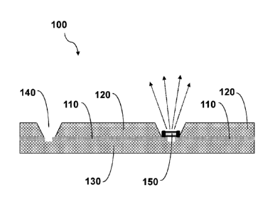
[0054] FIG. 1 provides a schematic cross-sectional side-view illustration of a
flexible UV
light generation sheet 100 in accordance with some embodiments. A UV-LED 150
is
electrically connected to individual segments of conductor 110 to allow
current to be applied
for UV light generation. Below conductor 110 is a support layer 130 and above
conductor 110
is a UV diffuse reflective layer 120. Support layer 130 may optionally be one
or more UV
diffuse reflective layers. UV diffuse reflective layer 120 is positioned so
light from UV-LED
150 can be emitted out of flexible UV light generation sheet 100. Support
layer 130 is
positioned below UV-LED 150 and may also be UV reflective such that stray
light is reflected
back. Openings 140 may be included in UV diffuse reflective adjacent layer 120
to allow light
from the UV-LED 150 to be emitted there through. The openings 140 may have a
variety of
shapes including circles, ovals, triangles, squares, rectangles, diamonds, and
other similar
shapes. The size of the opening may also vary but is sufficient to allow light
from a UV-LED
150 to pass through and may have an opening size from 0.5 to 20 mm, e.g. from
2 to 10 mm,
or from 3 to 6 mm. In one embodiment, the openings 140 may be formed by gaps
created
between adjacent longitudinal sides of one or more UV diffuse reflective
layers that are
wrapped to form the sheet. Optionally, conductor 110 may be segmented, such as
at
openings 140, to allow different contacts of electrical components to be
attached to the
individual segments.
[0055] As illustrated, a lens or focusing element is not positioned above UV-
LED 150.
When no lens or focusing element is used, the configuration advantageously
permits UV light
intensity to spread over a wider area and achieve a more uniform distribution
of UV light
intensity over a wider area, minimizing dim regions that may occur when
lensing or focusing
elements are included.
[0056] FIG. 2A provides a schematic cross-sectional end-view illustration and
FIG. 2B
provides a cross-sectional top-view illustration of a flexible UV light
generation sheet 200 in
accordance with some embodiments. FIG. 2A shows a flexible UV light generation
sheet 200
in which conductors 210 are optionally included in a ribbon or a flexible flat
cable and may be
joined or attached to one another by way of electrically insulating material
surrounding at least
a portion of one or more conductors. UV diffuse reflective layer 220 may be
positioned above
conductors 210, such that UV diffuse reflective layer 220 covers at least a
portion of
conductors 210 and/or any insulating material surrounding the conductors. It
will be
CA 03084762 2020-06-04
WO 2019/117853 PCT/1JS2017/065590
appreciated that UV diffuse reflective layer 220 may be in individual sections
positioned above
each conductor 210 or may a continuous layer positioned above any number of
conductors
210. Support layer 230 may be positioned below the conductors 210, and below
UV-LEDs
250, such that support layer 230 covers at least a portion of the conductors
210 and UV-LEDs
250 and/or any insulating material surrounding the conductors and UV-LEDs.
Optionally,
support layer 230 is a UV diffuse reflective layer. It will be appreciated
that support layer 230
may be in individual sections positioned below each conductor 210 or may a
continuous layer
positioned below any number of conductors 210 and UV-LEDs 250. It will be
appreciated that
a support layer may be an optional feature of the flexible UV light generation
sheets described
herein, as the structure of the UV-LEDs, conductors, a UV transparent
scattering or UV diffuse
reflective layer, and any additional layers, such as overlayers, may provide
sufficient structure
to the flexible UV light generation sheet such that a separate support layer
is not needed.
Optionally, UV diffuse reflective layer 220 or support layer 230 may be
provided as a jacketing
material of conductors 210.
[0057] FIG. 2B may correspond to a perpendicular view from those shown in FIG.
1 and
FIG. 2A. In flexible UV light generation sheet 200, conductors 210 are
included and shown
extending from edges of flexible UV light generation sheet 200. Conductors 210
are at least
partially covered by a UV diffuse reflective layer 220. UV-LEDs 250 are
illustrated as
positioned above several conductors 210, with an additional conductor 210 used
as a
common or current return line. Similar to FIG. 1, UV-LEDs 250 may be
positioned at openings
in UV diffuse reflective layer 220 and bridging segments of conductors 210. It
will be
appreciated that, as illustrated in FIG. 2B, UV-LEDs 250 may be individually
electrically
addressable. Allowing the UV-LEDs to be individually electrically addressable
may provide
good control to adjust the UV light within the fluid pathway to achieve an
uniform UV emission.
It will be appreciated that FIGs. 2A and 2B provide an array of multiple UV-
LEDs 250 with a
plurality of conductors 210, such as a non-regular array.
[0058] As an alternative to driving LEDs in series with a common current, LEDs
may be
driven in parallel with a common voltage. FIG. 3A provides a cross-sectional
schematic
illustration of a flexible UV light generation sheet 300 including a ribbon
cable. The ribbon
cable includes a plurality of round conductors 310, each depicted as a
stranded core cable. It
will be appreciated that solid core conductors are also useful. A UV-LED 350
is depicted as
positioned adjacent to and in electrical communication with two different
conductors, in
contrast to the configuration illustrated in FIGs. 1, 2A, and 2B, where a UV-
LED is positioned
11
to bridge segments of a single conductor. FIG. 3B provides a cross-sectional
schematic
illustration of a flexible UV light generation sheet 300 where one conductor,
for example the
center conductor, may be used as a heat sink, for example, to allow heat
generated by one or
more UV-LEDs to flow away from the UV-LEDs.
[0059] FIG. 4 provides a cross-sectional schematic illustration of a flexible
UV light
generation sheet 400 including a ribbon cable with a plurality of conductors
410, UV-LEDs 450
and adjacent layer 420. An additional overlayer 460 is depicted as positioned
above UV
diffuse reflective layer 420 and above UV-LEDs 450. Overlayer 460 is a UV
transparent layer,
allowing UV light generated by UV-LEDs 450 to transmit out from flexible UV
light generation
sheet 400. In addition, incident UV light may transmit through overlayer 460
and be reflected
by adjacent layer 420 back through overlayer 460 and into the medium above the
flexible UV
light generating sheet 400. Optionally, additional overlayer 460 may be a UV
transmissive
scattering layer, allowing UV light generated by UV-LEDs 450 to transmit out
from flexible UV
light generation sheet 400 and be scattered to more uniformly distribute the
light. A UV
transmissive scattering layer, also referred to as a UV haze layer or UV
transmissive
scattering layer, diffuses light over a wide range of angles. ASTM standard
D1003, describes
details of haze and transparency measurements, and defines haze as the ratio
of diffuse
transmittance to total luminous transmittance, which may correspond to the
percentage of light
passing through a layer that deviates from the incident beam greater than 2.5
degrees on
average. Optionally, overlayer 460 may correspond to an encapsulating layer,
which may
provide water resistance or other environmental protection to underlying
components.
Advantageous properties of an overlayer may include electrically insulation,
low water and
oxygen transmission rates, high mechanical toughness, and high thermal
conductivity.
Optionally a UV diffuse reflective underlayer 430 is positioned below the UV-
LEDs to redirect
any backward scattered light in the forward direction above the UV-LEDs. In
this embodiment,
little if any light is lost and less power is required to disinfect the fluid
stream.
[0060] FIG. 5 provides an alternative embodiment of a flexible UV light
generation sheet
500 including a ribbon cable with a plurality of conductors 510 and UV-LEDs
550. FIG. 5 is
similar to FIG. 4 except that the overlayer 560 is below adjacent reflector
layer 520. FIG. 6
provides a further alternative embodiment of a flexible UV light generation
sheet similar to
FIG. 4 and FIG. 5 except that the adjacent reflective layer 520 has been
removed. In this
12
Date recue / Date received 2021-11-30
CA 03084762 2020-06-04
WO 2019/117853 PCT/1JS2017/065590
embodiment, incident light would transmit through the overlayer 660 and be
reflected by
underlayer 630.
[0061] In some embodiments, a flexible UV light generation sheet makes use of
a flexible
circuit rather than a ribbon or flat flexible cable for providing electrical
connections to one or
more UV-LEDs. For example, FIG. 7A provides a schematic cross-sectional
illustration of a
flexible circuit-based UV light generation sheet 700. Here, flexible UV light
generation sheet
700 includes flexible circuit 715, which corresponds, for example to a
flexible conductive trace
712 supported on a flexible substrate film 714. As an example, flexible
conductive trace 712
may correspond to a thin copper layer and flexible film 714 may correspond to
a polymer film,
such as polyimide. UV-LEDs 750 may be positioned in electrical communication
with portions
of flexible conductive trace 712 and supported by flexible film 714. An
overlayer 760, such as
a UV transparent layer or a UV transmissive scattering layer, may be included,
depending on
the particular configuration. The overlayer 760 may protect the UV-LEDs from
the
environment including, for example, immersion in water. Advantageous
properties may
include electrically insulation, low water and oxygen transmission rates, high
mechanical
toughness, and high thermal conductivity. A reflective underlayer 730, and a
reflective layer
720, may be included, depending on the particular configuration.
[0062] Another embodiment depicting a flexible UV light generation sheet 700
using a
flexible circuit rather than a ribbon or flat flexible cable is shown in FIG.
7B. Here, flexible UV
light generation sheet 700 includes flexible circuit 715, which corresponds,
for example to a
flexible conductive trace 712 supported on a flexible film 714. As an example,
flexible
conductive trace 712 may correspond to a thin copper layer and flexible film
714 may
correspond to a polymer film, such as polyimide. UV-LEDs 750 may be positioned
in
electrical communication with portions of flexible conductive trace 712 and
supported by
flexible film 714. Openings may be included in in flexible film 714, to allow
UV light generated
by UV-LEDs 750 to be transmitted away from flexible UV light generation sheet
700.
Alternatively, flexible film 714 may be transparent to the emitted light from
UV-LEDs so
openings are not required. A reflective underlayer 730, and a reflective layer
720, may be
included, depending on the particular configuration.
UV Light Generation Assembly Configurations
[0063] A variety of UV light generation systems using the flexible UV light
generation sheets
described herein are contemplated. As an example, FIG. 8A depicts a UV light
generation
system 800A including a flexible UV light generation sheet 805 wrapped in a
helical
13
CA 03084762 2020-06-04
WO 2019/117853 PCT/1JS2017/065590
configuration around a tubular structure 815. In one embodiment, the UV light
generation
sheet 805 has opposing longitudinal sides that are adjacent or partially
overlap. The tubular
shape may correspond to the fluid path 825. In this way, flexible UV light
generation sheet
may be arranged to enclose a fluid path 825, corresponding to an interior
region of tubular
structure 815, for example. The fluid path 825 may be useful for flowing
liquids or gases
through a region illuminated by UV light for disinfecting or purifying the
liquids or gases.
Optionally, particles or objects may be suspended in the fluid and exposed to
the UV light for
disinfecting or purifying the particles or objects. Optionally, flexible UV
light generation sheet
805 and tubular structure 815 are flexible, allowing treatment system 800A to
adopt a bent or
curved configuration. Optionally, tubular structure 815 is a mandrel used to
form a tubular
shape when the flexible UV light generation sheet is wrapped. In this
embodiment, the
mandrel is removed to form a fluid pathway. In embodiments, tubular structure
815 is a UV
transparent tube, permitting UV light generated by UV-LEDs of flexible UV
light generation
sheet 805 to transmit into an interior of tubular structure 815. In this
embodiment, the UV
transparent tube may be considered part of the UV light generation system. In
one
embodiment, UV-LEDs of flexible UV light generation sheet 805 are arranged to
position at
least a first UV-LED in a configuration that is not directly opposed, across
the fluid path 825, to
any other UV-LED. Incidentally, UV-LEDs of flexible UV light generation sheet
805 are
arranged to position at least a first UV-LED in a configuration that is
directly opposed, across
the fluid path 825, to a UV diffuse reflective layer of flexible UV light
generation sheet 805.
This allows the UV light to reflect and become more uniformly distributed in
the fluid pathway.
In FIG. 8A, conductors 810 are also illustrated as extending from flexible UV
light generation
sheet 805 and may be connected to circuits or power sources. It will be
appreciated that for
direction of UV light into fluid path 825, UV-LEDs will be positioned facing
tubular structure
815. UV-LEDs are on the side of the sheet facing the interior and are not
visible from the
exterior as shown in FIG. 8A.
[0064] FIG. 8B is a perspective view to show the interior region of the UV
light generation
sheet 805. For purposes of illustration the tubular structure 815 is not shown
in FIG. 8B. The
UV light generation sheet 805 has openings 840 that align with UV-LEDs 850 on
the
conductors (not shown in FIG. 8B). The UV light generation sheet 805 may be
constructed of
a diffuse UV reflective layer 820. It will be appreciated that additional
overlayers or
underlayers may optionally be included in UV light generation sheet 805, e.g.,
such as a
reinforcing underlayer, a UV transparent overlayer, and/or a UV transmissive
scattering
14
CA 03084762 2020-06-04
WO 2019/117853 PCT/1JS2017/065590
overlayer. In one embodiment, the UV transparent overlayer has a UV
transmission of at least
80% at 250 nm. As shown in FIGS. 8A and 8B, the sheet 805 is wrapped closely
together and
may partially overlap to prevent a gap between the adjacent longitudinal
sides.
[0065] Optionally, a surface at the fluid pathway may be coated with or
treated with TiO2 or
another UV active photocatalytic material. Other photocatalytic materials
include metal oxides
such as SiO2, ZnO, Bi2W06, Bi20Ti20, Fe2O3, Nb2O5, BiTiO3, SrTiO3, or ZnW04,
and other
metal catalysts such as CuS, ZnS, W03, or Ag2003. Upon exposing TiO2 or
another light
active photocatalytic material UV light generated by LEDs, electrons and holes
may be
generated to allow oxidation and/or reduction of material coming into contact
with the TiO2 or
active photocatalytic material. For example, contacting a light activated
photocatalyst with
water or oxygen may result in generation of reactive oxygen species, such as
hydroxyl
radicals (OH) and superoxide (02-). These reactive oxygen species may be
useful for
degrading or destroying pathogens, toxins, or impurities.
[0066] An alternative arrangement of a UV light generation treatment system
800B including
flexible UV light generation sheet 805 is depicted in FIG. 80, where instead
of being helically
wrapped around the fluid path 825, the flexible UV light generation sheet 805
is longitudinally
wrapped around the fluid path 825. It will be appreciated that in the
illustration depicted in
FIG. 8C the longitudinal wrap around fluid path 825 is shown as incomplete for
purposes of
illustration. In practice, ends of flexible UV light generation sheet 805 may
optionally be
attached and/or joined to form a complete enclosed fluid path 825. This
prevents a gap
between the sides of the sheet 805 in FIG. 80. In FIG. 80, conductors 810 are
also illustrated
as extending from flexible UV light generation sheet 805. There are various
openings 840 in
the UV light generation sheet 805 that are positioned to align with the UV-
LEDs 850
connected to the conductors 810. It will be appreciated that additional
overlayers or
underlayers may optionally be included in UV light generation sheet 805, e.g.,
such as a
reinforcing underlayer, a UV transparent overlayer, and/or a UV transmissive
scattering
overlayer. In addition, the UV light generation sheet 805 shown in FIG. 80 may
be wrapped
around a transparent tube.
[0067] FIGs. 9A and 9B depict schematic cross-sectionals illustration of UV
light generation
systems 900A and 900B, such as using the flexible UV light generation sheet
depicted in FIG.
5, including UV diffuse reflective layer 920, underlayer 930, UV-LEDs 950,
flex circuit 915 and
overlayer 960, which may be positioned in various adjacencies, depending on
the
configuration. It will be appreciated that FIGs. 9A and 9B may represent a
cross-sectional
CA 03084762 2020-06-04
WO 2019/117853 PCT/1JS2017/065590
views of treatment system 800 of FIGs. 8A and 8B, for example. Light generated
by UV-LEDs
950 is directed into a fluid path defined as an interior space surrounded by
the flexible UV light
generation sheet. When UV light reaches the UV diffuse reflective layer 920,
the UV light is
reflected back into the fluid path, allowing for high levels of UV light
intensity to be generated
in the fluid path. In embodiments, reflective layer 920 is a highly diffuse
reflective material,
such as a material that reflects 98% or more of incident UV light, such as UV
light having
wavelengths between 100 nm and 400 nm, or any subrange thereof. As
illustrated, each UV-
LED 950 is positioned in a configuration that is not directly opposed to any
other UV-LED 950.
Stated another way, each UV-LED 950 is positioned in a configuration that is
directly opposed
to reflective layer 920 to allow UV light to reflect off reflective layer 920
and become more
uniformly distributed. It will be appreciated that, in the configuration
illustrated in FIGs. 9A-9B,
the flexible UV light generation sheet may not include openings in a UV
diffuse reflective layer.
Overlayer 960 is UV transparent and optionally UV scattering (e.g., hazy) or
comprises
photocatalysts on the surface. Overlayer 960 may optionally provide for
protection of
underlying or adjacent layers, and may, for example, provide protection
against penetration by
water or another fluid.
[0068] FIG. 10 depicts a schematic cross-sectional illustration of a light
generation
treatment system 1000. Such a configuration may be constructed similar to the
system 800
illustrated in FIGs. 8A and 8B, where a flexible UV light generation sheet is
helically wrapped
around a tubular structure or where a flexible UV light generation sheet is
longitudinally
wrapped around a tubular structure. However, for light generation treatment
system 1000, the
structure of the flexible UV light generation sheet is reversed from the other
embodiments.
This enables the generation of an uniform UV emission field at a distance from
the outer
surface. For example, treatment system 1000 includes overlayer 1060, UV-LEDs
1050,
reflective underlayer 1030, and interior region 1025. In FIG. 10, UV-LEDs 1050
are depicted
as arranged to direct light away from a central shaft 1025 defined by the
flexible UV light
generation sheet. Advantageously, overlayer 1060 may be a UV transmissive
scattering layer
allowing light generated by UV-LEDs 1050 to be scattered diffusely across a
range of
directions. Overlayer 1060 may also serve as an encapsulating layer, providing
water
repellency and environmental protection to underlying UV-LEDs, conductors, and
other
components.
[0069] Interior region 1025 may correspond to a tubular structure, such as a
hollow tube or
solid cylindrical structure, for example. An adhesive may be used to mount the
flexible UV
16
CA 03084762 2020-06-04
WO 2019/117853 PCT/1JS2017/065590
light generation sheet to the interior region 1025. As an example, interior
region may include
a central shaft. Alternatively, the interior region may be open. In one
example of a
construction method an open interior region 1025 may be formed by wrapping a
flexible UV
light generation sheet around a mandrel. Herein the light generation sheet may
be formed by
first wrapping the reflective underlayer 1030 around the mandrel without an
adhesive. A
second underlayer 1030 may then be wrapped around the first underlayer 1030
which
includes a thin adhesive layer so as to secure the form factor of the two
underlayers 1030 in
the shape of the mandrel but allowing the mandrel to be removed thereby
forming an open
interior region 1025.
[0070] Such a configuration is useful, for example, in embodiments where the
flexible UV
light generation treatment system 1000 is inserted into a container or fluid
pathway and used
to expose fluid, particles, or objects in the container or fluid pathway to UV
light. Treatment
system 1000 may correspond to a rod or stick that may be moved within the
container or fluid
pathway to target impurities in the stream. The movement may also induce
turbulence and/or
promote mixing.
[0071] FIG. 11 corresponds to two flexible UV light generation sheets opposing
each other
and depicts a schematic cross-sectional illustration of a flexible UV light
generation sheet
useful for generating an uniform UV emission field at a distance from the
flexible UV light
generation sheet. As illustrated, the flexible UV light generation sheet 1100
includes an
underlayer 1120, UV-LEDs 1150 supported by the substrate and an overlayer 1160
positioned
over underlayer 1120 and UV-LEDs 1150. Underlayer 1120 may correspond, for
example, to
a UV diffuse reflective layer. It will be appreciated that additional layers
may be included in
flexible UV light generation sheet 1100. For example multiple flexible UV
light generation
sheets may be used together to form a system. Flexible UV light generation
sheet 1100 may
be useful, for example, for lining walls of a container or vessel to allow
fluids, particles, or
objects within the container or vessel to be exposed to UV light for
disinfection, purification, or
other treatment purposes. Optionally, devices within a container or vessel,
such as used for
mixing a fluid or objects or particles suspended in a fluid, may have one or
more surfaces
lined with flexible UV light generation sheet 1100 to allow exposure of the
fluid, objects, or
particles to UV light for disinfection or purification purposes. As an
example, one or more
walls of a vessel, conduit, or pipe may be lined with flexible UV light
generation sheet 1100
and/or a surface of a mixing vane may be lined with flexible UV light
generation sheet 1100.
17
CA 03084762 2020-06-04
WO 2019/117853 PCT/1JS2017/065590
[0072] As another example, one or more flexible UV light generation sheets may
be
arranged in a pouch or pocket configuration, where a surface of a first
flexible UV light
generation sheet faces a surface of a second flexible UV light generation
sheet. Such a
configuration may correspond to two separate flexible UV light generation
sheets or may
correspond to a single flexible UV light generation sheet folded back on
itself to form a pouch
or pocket like configuration. As an example, for a rectangular pouch
configuration, three sides
of facing rectangular flexible UV light generation sheets may be joined or
attached to make a
rectangular pouch. Other shapes are possible.
[0073] As another example, multiple flexible UV light generation sheets may be
combined to
form a UV light generation system 1200, as depicted FIG. 12. In FIG. 12, UV
light generation
system 1200 includes a first flexible UV light generation sheet 1205 and a
second flexible UV
light generation sheet 1210. First flexible UV light generation 1205 sheet may
correspond to
flexible UV light generation sheet 900 as depicted in FIG. 9. Second flexible
UV light
generation sheet 1210 may correspond to flexible UV light generation sheet
1000 as depicted
in FIG. 10. As illustrated, first flexible UV light generation sheet 1205 and
second flexible UV
light generation sheet 1210 are arranged so that second flexible UV light
generation sheet
1210 is positioned inside first flexible UV light generation sheet 1210. In
addition, the UV-
LEDs of each flexible UV light generation sheet are depicted as not directly
opposed one
another UV-LEDs. For example, UV light from UV-LEDS of first flexible UV light
generation
sheet 1205 is directed towards a scattering layer or a reflective layer of
second flexible UV
light generation sheet 1210. Similarly, UV light from UV-LEDS of second
flexible UV light
generation sheet 1210 is directed towards a reflective layer of first flexible
UV light generation
sheet 1205. In this way, an annular region 1215 may be formed between first
flexible UV light
generation sheet 1205 and second flexible UV light generation sheet 1210, such
as to allow
fluid to flow between them and be treated by UV light.
[0074] As another example, a flexible UV light generation sheet may optionally
be a two-
sided sheet. Flexible two-sided flexible UV light generation sheet 1300 is
depicted in FIGs.
13A and 138. FIG. 13A shows a cross-sectional schematic illustration of two-
sided flexible
UV light generation sheet 1300 including reflective layer 1320 and scattering
overlayer 1360
covering reflective layer 1320 and UV-LEDs 1350. As illustrated, UV-LEDs 1350
are mounted
on both sides of two-sided flexible UV light generation sheet 1300 with the
reflective layer
1320 and scattering overlayer positioned on each side of two-sided flexible UV
light
generation sheet 1300. In this embodiment, UV-LEDs 1350 positioned on a first
side of the
18
CA 03084762 2020-06-04
WO 2019/117853 PCT/1JS2017/065590
two-sided flexible sheet 1300 do not back to any UV-LEDs positioned on a
second side of the
two-sided flexible sheet 1300. Flexible UV light generation sheet 1300 may be
correspond to a
flag type configuration, where flexible UV light generation sheet 1300 is
fixed on one end with
the other end free to move, such as in a fluid. FIG. 13B also shows a
supporting structure
1370 and that flexible UV light generation sheet 1300 is supported only, for
example, on one
end by supporting structure 1370. In some embodiments, however, a flexible UV
light
generation sheet may be supported on two or more or all ends by various
supporting
structures. Supporting structure 1370 may include power and communications
connections,
such as power/voltage supplies, control circuitry, or communications feeds,
for example
between UV-LEDs and/or UV photodetectors and external circuitry by way of one
or more
conductors. It will be appreciated that FIGs. 13B depicts a regular array of
multiple UV-LEDs
1350 and that any conductors included with the array are not illustrated.
UV Diffuse Reflective Layer
[0075] A variety of materials are useful as a UV diffuse reflective layer for
various flexible
UV light generation sheets and treatment systems described herein. For
example, a UV
diffuse reflective layer may comprise one or more polymers or a polymer layer,
such as a
polymer selected from the group consisting of a fluoropolymer, a polyimide, a
polyolefin, a
polyester, a polyurethane, a polyvinyl, polymethyl methacrylate, or variations
or derivatives
thereof. Example polymers include, but are not limited to, polyethylene
terephthalate (PET),
polyethylene naphthalate (PEN), poly ether ether ketone (PEEK), cyclic olefin
copolymer
(COO), polycarbonate (PC), polyphenylene sulfide (PPS), polyetherimide (PEI),
polyamideimide (PAI), polychloroprene, polyvinyl chloride (PVC),
polyvinylidene chloride
(PVDC), vinylidene chloride-vinyl chloride copolymers, vinyl chloride
copolymers, vinylidene
fluoride polymers, polyvinylidene fluoride (PVDF), fluorinated ethylene
propylene (FEP),
perfluoroalkoxy alkane (PEA), or polytetrafluoroethylene (PTFE). In one
embodiment, the UV
diffuse reflective layer may comprise an expanded polytetrafluoroethylene
(ePTFE). In some
embodiments, a UV reflective layer comprises a thin metal film. In some
embodiments, a UV
reflective layer comprises a dielectric stack. In some embodiments, a UV
diffuse reflective
layer exhibits a diffuse reflectivity of 50% or greater, 60% or greater, 70%
or greater, 80% or
greater, 90% or greater, 95% or greater, 97% or greater, 98% or greater, or
99% or greater for
UV light, such as light having wavelengths between 200 nm and 400 nm. Example
UV diffuse
reflective layers include those exhibiting a diffuse reflectivity (diffuse
reflective scattering)
percentage for UV light, such as light having wavelengths between 200 nm and
400 nm, 50%
19
or more (i.e., 50-100%), 60% or more, 70% or more, 80% or more, or 90% or
more. In some
embodiments, a UV diffuse reflective layer functions as an encapsulating,
water resistance, or
environmental protection layer.
[0076] A variety of exemplary materials that may be used as either a
reflective layer, such
as a reflective layer or a reflective underlayer. In publication "Reflectivity
Spectra for
Commonly Used Reflectors" by Martin Janacek, the author lists several
materials which have
greater than 97% reflectivity. In one embodiment the UV diffuse reflective
layer comprises
ePTFE. The ePTFE material comprises a microstructure of polymeric nodes and
fibrils that
demonstrates exceptional diffuse reflectivity in the UV spectrum. An exemplary
ePTFE for
the UV diffuse reflective layer, Gore DRPO, is produced by W.L. Gore &
Associates of
Newark, Delaware. FIG. 18 shows a plot of total reflectivity from 250 nm to
800 nm of
various thicknesses of skived PTFE along with Gore DRPO. This material is
described in US
Pat. No. 5,596,450 or US Pat. No. 6,015,610. While packed granular based PTFE
material
provides good diffuse reflectance properties, the node and fibril structure of
ePTFE provides
a much higher diffuse reflectance property and has higher mechanical strength.
[0077] The UV diffuse reflective layer may be thin and lightweight. Making the
UV diffuse
reflective layer lighter and less expensive to employ expands the applications
for the flexible
UV light generation sheet. In one embodiment the UV diffuse reflective layer,
including any
coating or filler, may have a thickness from 0.01 mm to 2 mm, e.g., from 0.05
to 1.5 mm or
from 0.1 to 1.2 mm. In one embodiment, the UV diffuse reflective layer has a
high index of
light reflection at a thickness of less than 0.3 mm.
UV Transparent and Scattering Layers
[0078] A variety of materials are useful as a UV transparent layers or UV
transmissive
scattering layer for various flexible UV light generation sheets and systems
described herein.
As noted above, UV transparent layers and scattering layers are useful, for
example, as
overlayers.
[0079] In embodiments, a UV transparent layer or UV transmissive scattering
layer may
comprise one or more polymers or a polymer layer, such as a polymer selected
from the
group consisting of a fluoropolymer, a polyimide, a polyolefin, a polyester, a
polyurethane, a
polyvinyl, polymethyl methacrylate, or variations or derivatives thereof.
Example polymers
include, but are not limited to, polyethylene terephthalate (PET),
polyethylene naphthalate
Date recue / Date received 2021-11-30
(PEN), poly ether ether ketone (PEEK), cyclic olefin copolymer (COC),
polycarbonate (PC),
polyphenylene sulfide (PPS), polyetherimide (PEI), polyamideimide (PAI),
polychloroprene,
polyvinyl chloride (PVC), polyvinylidene chloride (PVDC), vinylidene chloride-
vinyl chloride
copolymers, vinyl chloride copolymers, vinylidene fluoride polymers,
polyvinylidene fluoride
(PVDF), fluorinated ethylene propylene (FEP), perfluoroalkoxy alkane (PFA) or
polytetrafluoroethylene (PTFE). In some embodiments, a polymer useful as a UV
transparent
layer corresponds to a PTFE, such as an ePTFE, which is a highly inert
hydrophobic material.
Accordingly, the PTFE is chemically resistant and liquid-proof which is useful
when the UV
transparent layer or UV transmissive scattering layer is in contact with the
fluid stream. In
some embodiments, a UV transparent layer or UV transmissive scattering layer
functions as
an encapsulating, water resistance, or environmental protection layer.
[0080] Preferably, a UV transparent layer has a very low optical absorption
(e.g., less than
10%, less than 5%, or less than 1%) so that a very high percentage of the
light is transmitted
through the UV transparent layer. In some embodiments, a UV transparent layer
exhibits a
transparency for UV light of 50% or greater, 75% or greater, or 90% or
greater, such as light
having wavelengths between 100 nm and 400 nm. In one embodiment, the UV
transparent
overlayer has a UV transmission of at least 80% at 250 nm.
[0081] In addition to low optical absorption, an optional but desirable
property for an
overlayer is haze or scattering character. Haze is forward scattering of light
greater than 2.5
degrees from the optical transmission axis. This property will defocus the
light thereby
increasing the uniformity of the photon density in the fluid stream. In
embodiments, UV
transmissive scattering layers comprise UV transparent materials. Inclusion of
surface
features or one or more fibrils, nodes, pores, and the like in a transparent
material provides
more opportunities for scattering of light at surfaces or transitions between
materials of
different indices of refraction (e.g., air and polymer), and may provide a
scattering character or
haze to a material. Haze and scattering are further described in ASTM standard
D1003.
[0082] Exemplary overlayer materials are described in U.S. Pat. No. 5,374,473
and U.S.
Pat. No. 7,521,010. The patents describe a compressed ePTFE article which has
improved
properties over conventional cast or skived PTFE. FIG. 19 shows a plot of
transmission vs.
wavelength for three samples (51, S2, S3) of a compressed ePTFE article as
described in
the patents, along with FEP, PFA and ETFE (TefzelTm). The compressed ePTFE
articles
have a thickness
21
Date recue / Date received 2021-11-30
CA 03084762 2020-06-04
WO 2019/117853 PCT/1JS2017/065590
of 0.5 mil, while the FEP, PFA and ETFE have a thickness of 1 mil. In general,
thinner
thicknesses will have higher transmission percentages due to lower absorption
losses.
However, T = 1 ¨ R ¨ A (Transmission calculates as 100% minus reflection
losses R minus
absorption losses A) and in these films the reflection coefficient is much
larger than the
absorption coefficient (as calculated from this equation using optical
transmission and
reflection data on the same films). So even higher transmission numbers can be
attained by
not using air in the transmission path from the LED to the fluid medium. FIG.
20 shows a plot
of haze vs. wavelength for the same six articles. It will be appreciated that
in these samples
the higher percent transmission material has the lower haze. Depending on the
application,
one may choose to use a material with more scattering to promote light
diffusion and reduce
dark spots in the fluid stream even though the total optical power has been
reduced. The
overlayer material may have an optical transmission coefficient (T) of greater
than 70% and a
haze coefficient (H) of greater than 20% or preferably 1> 80% and H > 50%.
[0083] An overlayer may be adhered or laminated to a UV diffuse reflective
layer, a flex
circuit, a substrate or supporting layer, the UV-LEDs, or any other material
or layer in a flexible
UV light generation sheet. In one embodiment, an overlayer covers openings in
a UV diffuse
reflective layer that expose corresponding UV-LEDs.
[0084] Example UV transparent layers and UV transmissive scattering layers may
have
thicknesses of 7 microns to 100 microns.
[0085] UV transparent tube. In one embodiment, the assembly comprises a UV
transparent
tube and the flexible UV light generation sheet is wrapped around the tube. In
one
embodiment the flexible UV light generation sheet is wrapped along the outer
surface of the
tube. In other embodiments, the flexible UV light generation sheet is wrapped
and is placed
along the inner surface. The flexible UV light generation sheet is flexible
and lack a structural
rigidity to maintain the fluid pathway. A tube provides the necessary rigidity
for the fluid
pathway. This may be advantageous for in-line use for disinfection,
purification, sterilization, or
other treatment systems. The tube should be sufficient to withstand the
temperature of the
stream being treated and chemically resistant as needed.
[0086] In one embodiment, the UV transparent tube comprises a polymer, such as
a
fluoropolymer, a polyimide, a polyolefin, a polyester, a polyurethane, a
polyvinyl, polymethyl
methacrylate, polyethylene terephthalate (PET), polyethylene naphthalate
(PEN), poly ether
ether ketone (PEEK), cyclic olefin copolymer (COC), polycarbonate (PC),
polyphenylene
sulfide (PPS), polyetherimide (PEI), polyamideimide (PAI), polychloroprene,
polyvinyl chloride
22
CA 03084762 2020-06-04
WO 2019/117853 PCT/1JS2017/065590
(PVC), polyvinylidene chloride (PVDC), vinylidene chloride-vinyl chloride
copolymers, vinyl
chloride copolymers, vinylidene fluoride polymers, polyvinylidene fluoride
(PVDF), fluorinated
ethylene propylene (FEP), perfluoroalkoxy alkane (PFA) or
polytetrafluoroethylene (PTFE).
The material may be selected to provide a rigidity to the flexible UV light
generation sheet.
However, in other embodiments, the UV transparent tube may also be flexible.
Composite Structures
[0087] It will be appreciated that the various layers and components described
above may
be joined, adhered, or otherwise configured in a variety of manners to form a
composite
structure. For example, any one or more of a support layer, a substrate, a
conductor, a UV-
LED, a UV diffuse reflective layer, a UV transparent layer, a UV transmissive
scattering layer,
an encapsulating layer, and other components may be attached or positioned
adjacent to one
another using any suitable means. In some embodiments, layers may be laminated
to one
another to allow for layers to be joined or attached in a composite structure.
Example
lamination processes include thermal-based lamination processes and adhesive-
based
lamination processes. In some embodiments, layers or components may be
attached or
adjoined using one or more adhesives. Optionally, a continuous adhesive layer
is positioned
between two objects to allow the two objects to be adjoined, such as where an
adhesive layer
is positioned completely between the two objects at all points where the two
objects are
adjacent to one another. Optionally, a discontinuous adhesive layer, i.e.
adhesive dots or
adhesive lines, is positioned between two objects to allow the two objects to
be adjoined, such
as where a one or more adhesive layers are positioned between the two objects
at only a
subset of points where the two objects are adjacent to one another. Example
adhesives
include, but are not limited to, acrylics, polyamides, polyacrylamides,
polyesters, polyolefins,
polyurethanes, polysilicones or the like. Useful adhesives include those that
do not impact the
flexibility of the joined materials.
[0088] In embodiments, advantageous adhesives include UV stable adhesives. As
used
herein, the term "UV stable" indicates that a material, such as an adhesive,
is resistant to UV
light, allowing long term use without degrading. In some embodiments, a UV
stable material
may not significantly degrade when exposed to long durations of UV light, such
as years or
more. Suitable UV stable adhesives include silicones, acrylates or adhesives
with UV
absorbers or inhibitors added thereto. In addition, UV stable material may
advantageously be
non-absorbing (i.e., transparent) in the UV region or may exhibit only small
amounts of
absorption. Example UV stable materials include PTFE, ePTFE, fluorinated
ethylene
23
CA 03084762 2020-06-04
WO 2019/117853 PCT/1JS2017/065590
propylene (FEP) or perfluoroalkoxy alkane (PEA). Example UV stable adhesives
include
thermoplastic fluoropolymers. Preferred adhesives are FEP, a copolymer of
tetrafluoroethylene and hexafluoropropylene; PEA, a copolymer of
tetrafluoroethylene
monomers containing perfluoroalkoxy side chains, and EFEP, a copolymer of
ethylene,
tetrafluoroethylene, and hexafluoropropylene. Alternatively, copolymer resins
of
tetrafluoroethylene and perfluoroethylene-alkyl ether monomers (e.g., PAVE,
PMVE, and/or
CNVE) can be made with compositions and molecular weights to act as adhesives
that exhibit
excellent thermal and UV resistance (pressure sensitive, thermoplastic, or
crosslinked). Such
copolymer resins are disclosed, for example, in U.S. Pat. Nos. 7,488,781;
8,063,150;
8,623,963; 7,462,675; and 7,049,380.
UV-LED Configurations
[0089] UV-LEDs may be incorporated in the flexible UV light generation sheets
and
treatment systems described herein in a variety of manners. To distribute the
UV light within
the fluid pathway the UV-LEDs are arranged to form a regular spacing about the
flexible UV
light generation sheet. In other embodiment, non-regular spacing of the UV-
LEDs may also be
used. Multiple UV-LEDs are arranged in a parallel or series configuration. For
example, FIG.
14 provides an example circuit diagram 1400 showing multiple UV-LEDs 1450. As
illustrated,
an LED power supply 1405 is shown driving three sets of three series connected
UV-LEDs
1450, such that each UV-LED 1450 in a series is driven by the same amount of
current. FIG.
15 provides another example circuit diagram 1500 showing multiple UV-LEDs
1550. As
illustrated, LED power supply 1505 drives the UV-LEDs 1550 in parallel, such
that each UV-
LED 1550 is driven by the same voltage, for example. It will be appreciated
that the
configuration illustrated in FIG. 14 depicts not only UV-LEDs connected in
series, but also
series connected UV-LEDs that are also connected in a parallel configuration.
[0090] In some embodiments, UV-LEDs incorporated into flexible UV light
generation
sheets and treatment systems correspond to surface mounting devices, which may
be
advantageous for some implementations. For example, in some embodiment where
flat
flexible cable-based conductors are used, surface mounting of UV-LEDs may have
dimensions that match the pitch between conductors, allowing for seamless
integration and
manufacture of a flexible UV light generation sheet.
[0091] In some embodiments, UV-LEDs useful with the flexible UV light
generation sheets
and treatment systems described herein include UVA LEDs, exhibiting emission
between
wavelengths of 315 nm and 400 nm. In some embodiments, UV-LEDs useful with the
flexible
24
CA 03084762 2020-06-04
WO 2019/117853 PCT/1JS2017/065590
UV light generation sheets and treatment systems described herein include UVB
LEDs,
exhibiting emission between wavelengths of 280 nm and 315 nm. In some
embodiments, UV-
LEDs useful with the flexible UV light generation sheets and treatment systems
described
herein include UVC LEDs, exhibiting emission between wavelengths of 100 nm and
280 nm.
Exemplary UV-LEDs emit UV light with wavelengths between 260 nm and 265 nm,
between
270 nm and 280 nm, 305 and 315 nm. It will be appreciated, however, that the
wavelength of
UV light and the associated UV-LEDs may be selected that best matches or at
least partially
overlaps a destruction effectiveness curve of a target toxin or target
pathogen, for example.
As an example, a germicidal effectiveness curve for Escherichia coli may
exhibit a peak at
about 265 nm, and use of UV-LEDs emitting at this wavelength may provide an
advantage for
destroying these pathogens or toxins in the fluid pathway.
[0092] A variety of UV-LED structure types are suitable for use with the
flexible UV light
generation sheets and treatment systems described herein. In some embodiments,
a UV-
LED, one or more UV-LEDs or each UV-LED corresponds to a surface-mount device.
Use of
surface-mount devices are advantageous when making a flexible UV light
generation sheet or
a treatment system using a flat flexible cable, as certain flat flexible
cables have standard
pitches between conductors or widths that may match commercially available
surface-mount
type UV-LEDs. Other advantages provided by the use of surface-mount structures
include the
ability to use pick-and-place machinery to assemble portions of a flexible UV
light generation
sheet or treatment system. Other types of UV-LED structures are useful for
some
embodiments described herein, including through-hole LEDs, miniature LEDs,
high-power
LEDs, round, square, etc. In addition, any LED structure capable of generating
UV light of a
desired wavelength or wavelength region are useful with the embodiments
described herein.
For example, in some embodiments, a UV-LED has an AlGaN-structure, AIN
structure, a GaN
structure, or combinations of these.
[0093] It is to be understood that other UV light emitting semiconductors,
such as laser
diodes, for example VCSELs (vertical cavity surface emitting lasers), are
considered UV-LEDs
for the purposes of this patent application
Feedback and Intensity Control
[0094] It will be appreciated that exposure of toxins or pathogens to a
particular dose of UV
light may result in destruction of the toxins or pathogens, while lower doses
may not
completely destroy the toxins or pathogens. Similarly, if the toxin or
pathogen is present in
higher concentrations, the particular dose may not sufficiently destroy the
toxins or pathogens.
CA 03084762 2020-06-04
WO 2019/117853 PCT/1JS2017/065590
Advantageously, flexible UV light generation sheets and treatment systems
described herein
optionally include feedback mechanisms that permit control over the dose or
output intensity
of UV light generated. As an example, in some embodiments, a flexible UV light
generation
sheet or treatment system may include one or more UV sensors. For example, in
the
configurations illustrated in FIGs. 1-13B, one or more UV-LEDs may be
substituted for a UV
sensitive photodetector, such as a photodiode, that is positioned in
electrical communication
with a monitoring circuit that is used to provide feedback for increasing or
decreasing a current
and/or voltage used to drive one or more UV-LEDs in order to maintain a
suitable UV light
field.
[0095] FIG. 16 provides an example circuit diagram 1600 in which multiple UV-
LEDs 1650
are driven by LED power supply 1605. A UV sensitive photodetector 1670 is
depicted as
connected to a power monitor circuit 1680 that may be used to monitor a UV
light intensity or
power as output by the UV-LEDs 1650. By monitoring a UV light intensity or
power, the power
monitor circuit 1680 may provide information, used, such as by the power
monitor circuit or
another computer or control circuitry, to adjust the voltage or current
generated by LED power
supply 1605. In this way, the intensity of UV light can be monitored and
adjusted to
accommodate a target UV light dose or intensity useful for destroying toxins
or pathogens.
Methods of Making Treatment Systems
[0096] It will be appreciated that a variety of techniques may be employed for
making the
treatment systems and flexible UV light generation sheets described herein.
FIGs. 17A-17F
provide schematic overviews of an example aspects of an embodiment of a method
of making
a flexible UV light generation sheet. FIGs. 17A-17F provide schematic cross-
sectional front
views (1), side views (2), and top views (3) of a flexible UV light generation
sheet during steps
of a fabrication method. In FIG. 17A, multiple conductors 1702 are
illustrated, each
corresponding to a flat conductor of a flat flexible cable 1704. For purposes
of illustration, only
a section of a conductor cable is shown, but it will be appreciated that
conductors of any
number and size may be useful with various embodiments of the invention.
Optionally, the
jacketing surrounding the conductors may be UV transmissive or reflective
polymers. In FIG.
17B, the flat flexible cable 1704 is positioned adjacent to a substrate 1706.
In FIG. 17C, a UV
diffuse reflective layer 1708 is positioned adjacent to the flat flexible
cable 1704. In FIG. 17D,
openings 1710 are created at locations over two of the flat conductors 1702,
through both the
UV diffuse reflective layer 1708 and the jacketing of the flat flexible cable
1704. In addition, in
FIG. 17D, two of the flat conductors 1702 are segmented. Openings may be
created using
26
CA 03084762 2020-06-04
WO 2019/117853 PCT/1JS2017/065590
known processes in the industry, such as laser ablating or mechanical cutting.
In FIG. 17E,
UV-LEDs 1712 are positioned in each opening and joined to the respective flat
conductor
segments 1702. UV-LEDs may be attached using known processes in the industry,
such as
soldering or epoxying. In FIG. 17F, an overlayer 1714 is provided adjacent to
the UV diffuse
reflective layer, such as a UV transmissive scattering layer or a UV
transparent layer. The
attachment of the substrate, reflective, or transparent layers may be
facilitated with the use of
adhesives.
[0097] It will be appreciated that, for some embodiments, a separate substrate
may not be
required. For example a jacketing of a conductor may provide a suitable
support structure for
the conductors. Alternatively or additionally, an overlayer may not be
required for some
embodiments. It will further be appreciated that some embodiments may not
require a UV
diffuse reflective layer and so the UV diffuse reflective layer may be
substituted for a UV
transparent layer or a UV transmissive scattering layer.
[0098] The so formed flexible UV light generation sheets may be arranged in a
configuration
for exposing a fluid to UV light generated by the flexible UV light generation
sheet. For
example, the flexible UV light generation sheet may be arranged to enclose a
fluid pathway.
As another example, the flexible UV light generation sheet may be arranged to
form a tubular
shape. Optionally, the flexible UV light generation sheet may be helically
wrapped,
longitudinally wrapped, or circumferentially wrapped around a tube or central
shaft.
Optionally, the flexible UV light generation sheet may be arranged along an
interior surface of
a vessel or along a surface of a structure positioned within a vessel.
[0099] An overview of a method 2100 for the assembly of a UV light generating
sheet, such
as depicted in FIG. 7A, is shown in FIG. 21. At block 2105, multiple UV-LEDs
are attached to
the flexible circuit via known practices in the industry, such as surface
mounting technology,
which includes chip on board and SMD attachment. The UV-LEDs may be in
semiconductor
die form and flip-chipped or wirebonded to the flex circuit conductive traces
in a chip on board
process. Alternatively, the UV-LEDs may be already packaged in a SMD (surface
mount
device) carrier package, where the UV-LED packages are attached to the
flexible circuit with
conductive adhesives or solders. In some embodiments, the flexible circuit is
made by a
method that includes removing portions of a jacketing of the ribbon cable or
flat flexible cable
to expose UV-LEDs or attachment locations for the UV-LEDs. It will be
appreciated that the
flexible circuit may be substituted by a ribbon cable or other flexible
conductor assembly, as
described above. The UV LEDs have a predetermined spacing that is used to
create the
27
CA 03084762 2020-06-04
WO 2019/117853 PCT/1JS2017/065590
openings in block 2115. At block 2110, an adhesive layer is applied to a
surface of the UV
diffuse reflective sheet. As described herein the adhesive layer for each
layer or sheet may
be a continuous layer of film or a pattern of dots or lines. Preferable
adhesives are
thermoplastic fluoropolymers such as FEP (melting point (mp) 260 C), PEA (mp
305 C),
THV (mp 120 ¨ 230 C), and EFEP (mp 158¨ 196 C). In other embodiments, an
adhesive
layer may alternatively or additionally be applied to the top of the flexible
circuit. Openings are
cut into the UV diffuse reflective sheet at block 2115. Next, the UV diffuse
reflective sheet is
positioned to align openings with the UV-LEDs, at block 2120. By a similar
method, an
adhesive layer is applied to one surface of a transparent overlayer sheet, as
depicted at block
2125. In block 2130, the transparent overlayer sheet is positioned adjacent to
a surface of the
UV diffuse reflective sheet opposite to the flexible circuit. At block 2145,
the assembly is
cured in an oven or preferably in a heated press at a temperature from 125 to
325 C. In one
optional embodiment, the underlayer sheet can be added by a similar method at
blocks 2135
and 2140. Although optional block 2135 indicates that the adhesive layer may
be attached to
the underlayer sheet, the adhesive layer may alternatively or additionally be
applied to the
bottom of the flexible circuit.
[0100] The assembly of the double-sided UV light generating sheet, such as the
flag
configurations shown in FIGs. 13A and 13B, is similar to method 2100 as
depicted in FIG. 21.
In this case the UV-LEDs are mounted on two sides of the flexible circuit and
there is no
optional reflective underlayer sheet. In this design, the UV-LEDs are not back-
to-back so, for
practical purposes, the UV diffuse reflective sheet next to the top UV-LEDs
functions as the
UV diffuse reflective sheet underlying the UV-LEDs on the opposite side.
Alternatively, a
single-sided UV light generating sheet may be folded back on to itself to
create the flag
configurations in FIGs. 13A and 13B.
[0101] A method for making a light generating tube, such as depicted in FIGs.
8A and 8B,
involves wrapping a light generating sheet around a mandrel, such as a mandrel
of the
desired tubular shape. The wrapping may be helical, longitudinal, or
circumferential to form
the desired tubular shape. The mandrel is a cylindrical rod made of a
material, such as a
metal, that can withstand the cure temperatures used in the method. The
wrapped sheet is
then further wrapped with an underlayer, such as a reinforcing layer,
optionally with an
adhesive, and cured to solidify the assembly. Further protective coatings may
be applied over
the tube assembly. Cure steps may optionally be done at different points in
the method. The
mandrel is then removed from the tube assembly to create the fluid path.
28
CA 03084762 2020-06-04
WO 2019/117853 PCT/1JS2017/065590
[0102] A method 2200 is shown in FIG. 22 for wrapping a light generating sheet
in tubular
form. A flexible circuit comprising multiple UV-LEDs is assembled, in a manner
described
herein, at block 2205. An adhesive is applied to one surface of a UV diffuse
reflective layer at
block 2210, and openings are cut in the UV diffuse reflective layer at block
2215. The flexible
circuit is aligned with the UV diffuse reflective layer at block 2220 such
that the openings align
with the UV-LEDs to form a UV light generating sheet. The UV light generating
sheet is then
wrapped around a mandrel at block 2225. An underlayer, which optionally may be
a
reinforcing layer with reflective properties, is wrapped around the UV light
generating sheet
with an adhesive, as shown at blocks 2230 and 2235. Additional layers or
coatings may
optionally be added to the outside of the tubular assembly. At block 2240, the
assembly is
then cured, for example in an oven, and the mandrel is removed, at block 2245.
In one
embodiment, a lower melting point fluoropolymer adhesive EFEP is used so the
curing
temperature does not harm the flexible circuit. The product embodiment of this
method may
correspond to, for example, that shown in FIG. 9A.
[0103] Another method 2300 is shown in FIG. 23, which may form a product
corresponding
to, for example, that shown in FIG. 9B. At block 2305, a transparent overlayer
(e.g., layer 960
in FIG. 9B), is wrapped around a mandrel to form a tube, optionally with an
adhesive applied
at block 2310. The transparent overlayer can be made of materials described
previously. The
transparent overlayer can optionally be multilayer wrapped several times with
an adhesive to
secure the transparent overlayer to itself but not to the mandrel. In other
embodiments, the
transparent overlayer is a tube that is slid over the mandrel. The transparent
overlayer is
optionally cured at this stage. In an exemplary method, a preferred
transparent overlay
material is the aforementioned compressed ePTFE material, the adhesive is FEP,
and the
tubular structure is cured at 280 C (a temperature greater than the adhesive
melting
temperature but less than the melting temperature of the transparent overlay
material). An
alternative method of fabricating the transparent overlayer (e.g., layer 960
in FIG. 9B), is to
slide a pre-manufactured FEP tube over the mandrel. In this example, the
following cure
temperature steps should be less than the melting temperature of the FEP so as
to enable the
mandrel to be removed from the tubular assembly. After the transparent tube is
formed, the
rest of the method is similar to that described in FIG. 22. For example, a
flexible circuit
comprising multiple UV-LEDs is assembled at block 2315. An adhesive is applied
to one
surface of a UV diffuse reflective layer at block 2320, and openings are cut
in the UV diffuse
reflective layer at block 2325. The flexible circuit is aligned with the
reflective layer at block
29
CA 03084762 2020-06-04
WO 2019/117853 PCT/1JS2017/065590
2330 such that the openings in the layer align with the UV-LEDs to form the UV
light
generating sheet. The UV light generating sheet is then wrapped around the
transparent
overlayer at block 2335. An additional underlayer, which optionally may be a
reinforcing layer
or UV diffuse reflective layer, is wrapped around the assembly using an
adhesive layer, as
shown at blocks 2340 and 2345. Additional layers or coatings may optionally be
added to the
outside of the UV light generating sheet. At block 2350, the assembly is then
cured, for
example in an oven, and the mandrel is removed, at block 2355.
[0104] The methods shown by FIGs. 21-23 create openings in the UV diffuse
reflective
sheet. In other embodiments, openings may be created by gaps between adjacent
longitudinal sides as described by the methods in FIGs. 24-26. Regardless of
the method of
making UV light generating system, once in use the process may comprise
energizing the
multiple UV-LEDs to generate UV light, wherein at least a portion of the
generated UV light
from the multiple UV-LEDs passes through the corresponding openings and into
the fluid
pathway.
[0105] In one embodiment, reflective layers may be wrapped by the method that
is shown
by FIGs. 24A-24E. A mandrel 2402, e.g., a cylindrical rod, is used to form a
tubular UV light
generation system 2400 and once formed the mandrel 2402 is removed to form the
fluid path.
In one embodiment as shown in FIG. 24A, a transparent material 2404 is wrapped
around the
mandrel 2402 to form an overlayer. The wrapping is done to prevent gaps
between the
adjacent longitudinal sides of the transparent material 2404. Optionally,
adjacent longitudinal
sides of the transparent material overlap. In other embodiments, a transparent
overlayer that
is tubular may be fitted around the mandrel 2402, by sliding the transparent
overlayer over the
mandrel 2402. The overlayer may have an adhesive surface of a continuous
transparent
adhesive or by a pattern of adhesive dots or adhesive lines facing outward.
Next, a UV
diffuse reflective layer 2406 is wrapped around the mandrel 2402, or overlayer
if present.
When being wrapped, a gap 2408 is formed between adjacent, e.g., nearby,
longitudinal sides
of the UV diffuse reflective layer 2406. The UV diffuse reflective layer 2406
is wrapped along
the length of the mandrel to the desired size. The UV diffuse reflective layer
2406 may have
an adhesive surface of a transparent adhesive or by a pattern of adhesive dots
or adhesive
lines facing outward. In one embodiment, the UV diffuse reflective layer 2406
is flexible and
may be made of a UV stable material, e.g., expanded polytetrafluoroethylene.
The gap 2408
may be substantially uniform between the adjacent sides to provide a
separation distance
between the adjacent sides from 0.5 to 100 mm, preferably 0.5 to 20 mm, e.g.,
1 to 25 mm, or
CA 03084762 2020-06-04
WO 2019/117853 PCT/1JS2017/065590
from 3 to 15 mm. A flexible circuit 2410 having multiple UV-light emitting
diodes 2412 is
positioned to align the UV-light emitting diodes 2412 with the gap 2408. This
allows the UV
light to be transmitted into the interior of the UV light generating system
2400 when in use.
Although one flexible circuit is shown in FIG. 24C, in further embodiments,
multiple flexible
circuits may be used adjacent to the UV diffuse reflective layer 2406. When
multiple flexible
circuits are used, UV-light emitting diodes are off-set to achieve a wide
distribution of UV light
within the UV light generating system 2400. In FIG. 24D, an underlayer 2414 is
wrapped over
the UV diffuse reflective layer and flexible circuit. The wrapping is done to
prevent gaps
between the adjacent longitudinal sides of the underlayer 2414. Optionally,
adjacent
longitudinal sides of underlayer 2414 overlap. One or more curing processes
may optionally
be included in the method depicted in FIGs. 24A-24E, and following FIG. 24E,
the mandrel
2402 may be removed to create an internal fluid path.
[0106] Optionally, flexible circuit 2410 may itself include a diffuse UV
reflective overlayer
with openings included at the positions of UV LEDs 2412, as described above.
Such a flexible
circuit may alternatively be wrapped in a helical fashion around the mandrel
2402, or overlayer
2404 if present, with the gap 2408 having a width that is greater than or
equal to the width of
flexible circuit 2410 to allow flexible circuit 2410 to fit into the helical
gap 2408, as indicated in
FIG 24F. This configuration may be used in place of or in addition to that
depicted in FIG.
24D. This configuration benefits from a longer flexible circuit 2410 that may
include more UV-
LEDs and enables tighter curvatures with the tube assembly in a bent
configuration.
[0107] In a further embodiment, the method may involve wrapping a second UV
diffuse
reflective layer 2516 as shown in FIGs. 25A-25F. As discussed above, a first
UV diffuse
reflective layer 2506 is wrapped around the mandrel 2502, and optionally, the
transparent
material 2504 that forms the overlayer, such that a first gap 2508 is present
between adjacent,
e.g. nearby, longitudinal sides of first UV diffuse reflective layer 2506. In
FIG. 25C, the
second UV diffuse reflective layer 2516 is wrapped around the first UV diffuse
reflective layer
2506. In one embodiment, the second UV diffuse reflective layer 2516 is
counter-wrapped in
a direction that is opposite to the first UV diffuse reflective layer 2506. In
further
embodiments, additional UV diffuse reflective layers may be used. The second
gap 2518
between adjacent, e.g., nerarby, longitudinal sides of the second UV diffuse
reflective layer
2516 overlap with the first gap 2508 to form openings 2520. As discussed
herein, the
openings 2520 may have a variety of shapes and sizes. The openings 2520
correspond to the
pitch of the spacing of UV-LEDs 2512 on a flex circuit 2510. In one example, a
0.5 inch wide,
31
CA 03084762 2020-06-04
WO 2019/117853 PCT/1JS2017/065590
0.01 inch thick, ePTFE layer was wrapped at a pitch of 17 mm with a gap of 4
mm in the right
hand direction and then a second ePTFE layer was crossed wrapped in the left
hand direction
at a pitch of 17 mm with a gap of 4 mm. The resulting opening in the
reflective layers is 4 mm
diamond on a pitch of 17 mm. In one embodiment, the overlap of the first gap
and second gap
may create several different openings. For example, there may be additional
openings on the
back side (not shown in FIG. 250) that are spaced halfway between the openings
on the top
side.
[0108] FIG. 25D shows the flex circuit 2510 having UV-LEDs 2512 laid straight
in a
longitudinal manner. In one embodiment, multiple flex circuits may be used. In
another
embodiment, the method includes helically wrapping a flex circuit having UV-
LED in a helical
fashion around the tube, the spacing of the UV-LEDs being such that they align
with the
openings. This embodiment benefits from a longer flexible circuit that enables
tighter
curvatures with the tube assembly in a bent configuration. As shown in FIG.
25F, optional
underlayer 2514 is wrapped around the assembly, which may have reflective or
diffuse
reflective properties.
[0109] To complete the tubular UV light generation system 2500 assembly, the
assembly is
then cured and the mandrel 2502 is removed to create the internal fluid path.
[0110] As previously described, an optional embodiment for the transparent
overlayer is to
include photocatalysts such as TiO2 on the surface that is exposed to the
fluid medium. In
previously described embodiments, the overlayer is positioned above the UV-LED
such that
the emitted light path is from LED to photocatalyst to fluid medium. Since the
photocatalysts
in touch with the fluid medium are generally more effective at generating
reactive oxygen
species that can disinfect the fluid stream, it may be desirable to have an
optical path from
LED through fluid stream to surface photocatalysts (e.g., on other side of
tube). FIGS. 26A
and 26B depict an embodiment of forming the transparent overlayer that will
enable the light
emitted from the UV-LED to impinge on the photocatalysts from the fluid medium
side. A first
transparent overlayer 2603 is wrapped around mandrel 2602 with a gap 2605 as
shown in
FIG. 26A. A second overlayer 2607, comprising a photocatalytic surface layer,
optionally of
the same width as gap 2605, is then wrapped in the gap of transparent
overlayer 2603 as
shown in FIG. 26B. At this stage in the process the transparent overlayer
equivalent to FIG.
24A or FIG. 25A is finished and the various steps described in FIGs 24B-24F or
25B-25F can
be implemented to finish construction of the photocatalytic light generating
tube. An optional
32
CA 03084762 2020-06-04
WO 2019/117853 PCT/1JS2017/065590
embodiment is described in FIG. 24F with the addition of a photocatalytic
layer to the UV
reflective layer 2406.
Additional Examples
[0111] Additional non-limiting examples are further described.
[0112] El. A method of making an ultraviolet (UV) light generation system, the
method
comprising: wrapping a first UV diffuse reflective layer in a first direction
around a mandrel
with a first gap between adjacent longitudinal sides of the first UV diffuse
reflective layer,
wherein the first UV diffuse reflective layer is flexible; and positioning a
flexible circuit including
multiple UV-light emitting diodes (UV-LEDs) adjacent to the first UV diffuse
reflective layer,
wherein the positioning of the flexible circuit includes aligning the multiple
UV-LEDs to
correspond to the first gap.
[0113] E2. The method of El, further comprising wrapping a second UV diffuse
reflective
layer in a second direction around the mandrel and the first UV diffuse
reflective layer with a
second gap between adjacent longitudinal sides of the second UV diffuse
reflective layer,
wherein the second UV diffuse reflective layer is flexible, and wherein a
portion of the first gap
and a portion of the second gap overlap to generate a plurality of openings.
[0114] E3. The method of E2, wherein the positioning the flexible circuit
includes aligning
the multiple UV-LEDs to correspond to the plurality openings.
[0115] E4. The method of E2, wherein each of the multiple UV-LEDs is
positioned to direct
generated UV light through a corresponding opening.
[0116] E5. The method of any one of El-E4, wherein wrapping of the first UV
diffuse
reflective layer includes helically wrapping.
[0117] E6. The method of any one of El-E5, wherein each of the multiple UV-
LEDs is
positioned to direct generated UV light through the first gap.
[0118] E7. The method of any one of El-E6, wherein aligning the multiple UV-
LEDs
includes aligning one or more UV-LEDs of a first flexible circuit at a first
subset of the plurality
of openings and aligning one or more UV-LEDs of a second flexible circuit at a
second subset
of the plurality of openings.
[0119] E8. The method of E7, wherein the first subset of the plurality of
openings and the
second subset of the plurality of openings are positioned on opposite sides of
the mandrel.
[0120] E9. The method of E7, wherein the first subset of the plurality of
openings and the
second subset of the plurality of openings are offset from one another.
33
CA 03084762 2020-06-04
WO 2019/117853 PCT/1JS2017/065590
[0121] E10. The method of any one of E1-E9, further comprising generating the
flexible
circuit.
[0122] El 1. The method of E10, wherein generating the flexible circuit
includes attaching
the multiple UV-LEDs.
[0123] E12. The method of Ell, wherein attaching the multiple UV-LEDs includes
surface
mounting the multiple UV-LEDs on the flexible circuit.
[0124] E13. The method of E10, wherein the flexible circuit comprises a ribbon
cable or flat
flexible cable and wherein generating the flexible circuit includes attaching
the multiple UV-
LEDs to the ribbon cable or flat flexible cable.
[0125] E14. The method of E13, wherein generating the flexible circuit further
includes
removing portions of a jacketing of the ribbon cable or flat flexible cable.
[0126] E15. The method of any one of E1-E14, further comprising wrapping an
underlayer
around the mandrel, the first UV diffuse reflective layer, and the flexible
circuit.
[0127] E16. The method of E15, wherein the underlayer is a reinforcing
underlayer.
[0128] E17. The method of E15, wherein the underlayer is a UV diffuse
reflective
underlayer.
[0129] E18. The method of E15, further comprising applying an adhesive between
the
underlayer the flexible circuit and the first UV diffuse reflective layer.
[0130] E19. The method of any one of El-E18, further comprising wrapping an
overlayer
around the mandrel, wherein wrapping the first UV diffuse reflective layer
around the mandrel
includes wrapping the first UV diffuse reflective layer around the overlayer
and the mandrel.
[0131] E20. The method of any one of El-E18, further comprising positioning a
tubular
overlayer around the mandrel, wherein wrapping includes wrapping the first UV
diffuse
reflective layer around the tubular overlayer and the mandrel.
[0132] E21. The method of any one of E19 or E20, wherein the overlayer or
tubular
overlayer is a UV transparent overlayer, preferably having a UV transmission
of at least 80%
at 250 nm.
[0133] E22. The method of any one of E19 or E20, wherein the overlayer or
tubular
overlayer is a UV transmissive scattering overlayer.
[0134] E23. The method of any one E19 or E20, wherein the overlayer or tubular
overlayer
comprises a photocatalyst, preferably comprises TiO2.
34
CA 03084762 2020-06-04
WO 2019/117853 PCT/1JS2017/065590
[0135] E24. The method of any one of E19 or E20, further comprising applying
an adhesive
between the first UV diffuse reflective layer and the overlayer or tubular
overlayer, preferably
wherein the adhesive is a fluorinated ethylene propylene (FEP) adhesive.
[0136] E25. The method of any one of E1-E24, further comprising energizing the
multiple
UV-LEDs to generate UV light, wherin at least a portion of the generated UV
light from the
multiple UV-LEDs passes through the corresponding openings and into the fluid
pathway.
[0137] E26. The method of any one of E1-E25, further comprising removing the
mandrel.
[0138] E27. An ultraviolet (UV) light generation system made by the method of
any one of
E1-E26.
[0139] E28. An ultraviolet (UV) light generation system comprising: a first UV
diffuse
reflective layer arranged about a fluid pathway, wherein adjacent longitudinal
sides of the first
UV diffuse reflective layer are separated by a first gap, wherein the first
gap runs in a first
direction, and wherein the first UV diffuse reflective layer is flexible; a
second UV diffuse
reflective layer arranged about the first UV diffuse reflective layer, wherein
adjacent
longitudinal sides of the second UV diffuse reflective layer are separated by
a second gap,
wherein the second gap runs in a second direction, wherein the second UV
diffuse reflective
layer is flexible, and wherein the first and second gap overlap to generate a
plurality of
openings; and a flexible circuit including multiple UV-light emitting diodes
(UV-LEDs), wherein
the flexible circuit is positioned adjacent to the second UV diffuse
reflective layer to align the
multiple UV-LEDs at the plurality of openings.
[0140] E29. The UV light generation system of E28, wherein the first UV
diffuse reflective
layer is cylindrically wrapped about the fluid pathway, or wherein the second
UV diffuse
reflective layer is cylindrically wrapped about the first UV diffuse
reflective layer, or both.
[0141] E30. The UV light generation system of E28 or E29, wherein the first UV
diffuse
reflective layer is helically wrapped about the fluid pathway, or wherein the
second UV diffuse
reflective layer is helically wrapped about the first UV diffuse reflective
layer, or both.
[0142] E31. The UV light generation system of any one of E28-E30, further
comprising an
overlayer arranged about and defining the fluid pathway, wherein the first UV
diffuse reflective
layer is wrapped about the overlayer.
[0143] E32. The UV light generation system of E31, wherein the overlayer is a
UV
transparent overlayer, preferably having a UV transmission of at least 80% at
250 nm.
[0144] E33. The UV light generation system of E31, wherein the overlayer is a
UV
transmissive scattering overlayer.
CA 03084762 2020-06-04
WO 2019/117853 PCT/1JS2017/065590
[0145] E34. The UV light generation system of E31, wherein the overlayer
comprises a
photocatalyst, preferably comprises TiO2.
[0146] E35. The UV light generation system of E31, wherein the overlayer
covers at least a
portion of the plurality of openings.
[0147] E36. The UV light generation system of E31, wherein the overlayer is UV
stable.
[0148] E37. The UV light generation system of E31, wherein the overlayer is
adhered to the
first UV diffuse reflective layer or laminated to the first UV diffuse
reflective layer, preferably
the overlayer comprises a photocatalyst, and more preferably comprises TiO2.
[0149] E38. The UV light generation system of any one of E28-E37, wherein the
first UV
diffuse reflective layer does not include UV absorbing filler material, or
wherein the second UV
diffuse reflective layer does not include UV absorbing filler material, or
both.
[0150] E39. The UV light generation system of any one of E28-E38, wherein the
first UV
diffuse reflective layer is UV stable, or wherein the second UV diffuse
reflective layer is UV
stable or both.
[0151] E40. The UV light generation system of any one of E28-E39, further
comprising an
underlayer wrapped around the flexible circuit, the first UV diffuse
reflective layer, and the
second UV diffuse reflective layer.
[0152] E41. The UV light generation system of E40, wherein the underlayer is a
reinforcing
underlayer.
[0153] E42. The UV light generation system of E40, wherein the underlayer is a
UV diffuse
reflective underlayer.
[0154] E43. The UV light generation system of any one of E28-E42, wherein the
multiple
UV-LEDs are positioned to direct generated UV light into the fluid pathway.
[0155] E44. The UV light generation system of any one of E28-E43, wherein at
least a first
UV-LED of the multiple UV-LEDs is positioned in a configuration about the
fluid pathway that
is not directly opposed to any other of the multiple UV-LEDs.
[0156] E45. The UV light generation system of any one of E28-E44, wherein the
fluid
pathway corresponds to a tubular shape.
[0157] E46. The UV light generation system of any one of E28-E45, wherein the
fluid
pathway corresponds to a liquid pathway and wherein exposing a liquid stream
in the liquid
pathway to UV light generated by the multiple UV-LEDs reduces impurities
within the liquid
stream or reduces impurities associated with particles suspended in the liquid
stream.
36
CA 03084762 2020-06-04
WO 2019/117853 PCT/1JS2017/065590
[0158] E47. The UV light generation system of any one of E28-E46, wherein the
fluid
pathway corresponds to a gas pathway and wherein exposing a gas stream in the
gas
pathway to UV light generated by the multiple UV-LEDs reduces impurities
within the gas
stream or reduces impurities associated with particles suspended in the gas
stream.
[0159] E48. The UV light generation system of any one of E28-E47, wherein the
flexible
circuit further includes a UV sensitive photodetector, wherein the UV
sensitive photodetector
is positioned at one of the plurality of openings.
[0160] E49. The UV light generation system of any one of E28-E48, further
comprising an
adhesive layer for adhering two or more components of the UV light generation
system to one
another.
[0161] E50. The UV light generation system of E49, wherein the adhesive layer
adheres a
layer, an overlayer, or an underlayer to other components of the UV light
generation system.
[0162] E51. The UV light generation system of E49, wherein the adhesive layer
corresponds to a UV transparent layer, preferably wherein the adhesive is a
fluorinated
ethylene propylene (FEP) adhesive.
[0163] E52. The UV light generation system of E49, wherein the adhesive layer
is UV
stable.
[0164] E53. The UV light generation system of any one of E28-E52, wherein the
flexible
circuit corresponds to a ribbon cable or a flat flexible cable.
[0165] E54. The UV light generation system of any one of E28-E53, wherein each
of the
multiple UV-LEDs are individually electrically addressable.
[0166] E55. The UV light generation system of any one of E28-E54, wherein at
least a
portion of UV light generated by the multiple UV-LEDs is reflected by a UV
diffuse reflective
layer of the UV light generation system.
[0167] E56. The UV light generation system of any one of E28-E55, wherein the
multiple
UV-LEDs are positioned about the UV light generation system in a configuration
to generate a
uniform UV emission field within the fluid pathway.
[0168] E57. The UV light generation system of any one of E28-E56, wherein the
fluid
pathway includes straight or curved sections.
[0169] E58. The UV light generation system of any one of E28-E57, wherein one
or more
layers, underlayers, or overlayers of the UV light generation system are
flexible or exhibit an
elastic modulus of between 0.001 GPa and 3.0 GPa.
37
CA 03084762 2020-06-04
WO 2019/117853 PCT/1JS2017/065590
[0170] E59. The UV light generation system of any one of E28-E58, wherein one
or more
layers, underlayers, or overlayers of the UV light generation system comprise
polytetrafluoroethylene or expanded-polytetrafluoroethylene (e-PTFE).
[0171] E60. The UV light generation system of any one of E28-E59 made by the
method of
any one of E1-E27.
[0172] E61. The method of any one of E1-E27, wherein the UV light generation
system
comprises the UV light generation system of any one of E28-E59.
[0173] E62. A method of making an ultraviolet (UV) light generation system,
the method
comprising: generating a plurality of openings in a UV diffuse reflective
layer, wherein the UV
diffuse reflective layer is flexible; and positioning a flexible circuit
adjacent to the UV diffuse
reflective layer, wherein the flexible circuit includes multiple UV-light
emitting diodes (UV-
LEDs), and wherein the multiple UV-LEDs are aligned at corresponding openings
in the UV
diffuse reflective layer.
[0174] E63. The method of E62, wherein generating the plurality of openings
includes
removing portions the UV diffuse reflective layer.
[0175] E64. The method of E62 or E63, further comprising generating the
flexible circuit.
[0176] E65. The method of E64, wherein generating the flexible circuit
includes attaching
the multiple UV-LEDs on a flexible circuit.
[0177] E66. The method of E65, wherein attaching the multiple UV-LEDs includes
surface
mounting the multiple UV-LEDs on the flexible circuit.
[0178] E67. The method of E64, wherein the flexible circuit comprises a ribbon
cable or flat
flexible cable and wherein generating the flexible circuit includes attaching
the multiple UV-
LEDs to the ribbon cable or flat flexible cable.
[0179] E68. The method of E64, wherein generating the flexible circuit further
includes
removing portions of a jacketing of the ribbon cable or flat flexible cable.
[0180] E69. The method of any one of E62-E68, wherein the flexible circuit is
a two-sided
flexible circuit, wherein generating the plurality of openings in the UV
diffuse reflective layer
includes generating a first plurality of openings in a first UV diffuse
reflective layer and
generating a second plurality of openings in a second UV diffuse reflective
layer UV, and
wherein positioning the flexible circuit includes aligning a first portion of
the multiple UV-LEDs
that are present on a second side of the two-sided flexible circuit with
corresponding openings
of the first UV diffuse reflective layer and aligning a second portion of the
multiple UV-LEDs
that are present on a second side of the two-sided flexible circuit with
corresponding openings
38
CA 03084762 2020-06-04
WO 2019/117853 PCT/1JS2017/065590
of the second UV diffuse reflective layer, thereby making a two-sided UV light
generation
system.
[0181] E70. The method of any one of E62-E69, further comprising arranging the
UV
diffuse reflective layer and the flexible circuit such that at least portions
of the flexible circuit
are positioned back-to-back, thereby making a two-sided UV light generation
system.
[0182] E71. The method of any one of E62-E70, further comprising arranging a
second UV
light generation system adjacent to the UV light generation system such that
at least a portion
of the flexible circuit is positioned adjacent to a portion of a second
flexible circuit of the
second UV light generation system, thereby making a two-sided UV light
generation system.
[0183] E72. The method of any one of E62-E71, further comprising positioning a
UV diffuse
reflective underlayer adjacent to the flexible circuit.
[0184] E73. The method of E72, further comprising applying an adhesive between
the UV
diffuse reflective underlayer and the UV diffuse reflective layer.
[0185] E74. The method of E72, wherein the UV diffuse reflective underlayer is
flexible.
[0186] E75. The method of any one of E62-E74, further comprising positioning
an overlayer
adjacent to the UV diffuse reflective layer.
[0187] E76. The method of E75, wherein the overlayer is a UV transparent
overlayer,
preferably having a UV transmission of at least 80% at 250 nm.
[0188] E77. The method of E75, further comprising applying an adhesive between
the
overlayer and the UV diffuse reflective layer, preferably wherein the adhesive
is a fluorinated
ethylene propylene (FEP) adhesive.
[0189] E78. The method of E75, wherein the overlayer is flexible.
[0190] E79. The method of E75, wherein the overlayer comprises a
photocatalyst,
preferably a TiO2 surface coating or wherein the UV transparent overlayer is
attached to a
TiO2 overlayer.
[0191] E80. The method of E75, further comprising applying a TiO2 surface
coating to the
overlayer or attaching a TiO2 further overlayer to the overlayer.
[0192] E81. The method of E75, wherein the overlayer is a UV transmissive
scattering
overlayer.
[0193] E82. The method of any one of E62-E81, further comprising heating the
UV diffuse
reflective layer.
[0194] E83. The method of any one of E62-E82, further comprising applying
pressure to the
UV diffuse reflective layer.
39
CA 03084762 2020-06-04
WO 2019/117853 PCT/1JS2017/065590
[0195] E84. The method of E82, wherein heating the UV diffuse reflective layer
includes
heating the UV diffuse reflective layer and an underlayer, an overlayer, or
both an underlayer
or an overlayer.
[0196] E85. The method of any one of E62-E84, further comprising energizing
the multiple
UV-LEDs to generate UV light, wherein at least a portion of the generated UV
light from the
multiple UV-LEDs passes through the corresponding openings in the UV diffuse
reflective
layer.
[0197] E86. The method of any one of E62-E85, further comprising wrapping the
flexible
circuit and the UV diffuse reflective layer around a mandrel.
[0198] E87. The method of E86, wherein wrapping includes helically,
longitudinally, or
circumferentially wrapping the flexible circuit and the UV diffuse reflective
layer around the
mandrel.
[0199] E88. The method of E86, further comprising wrapping an underlayer
around the
flexible circuit and the UV diffuse reflective layer.
[0200] E89. The method of E88, wherein the underlayer is a reinforcing
underlayer.
[0201] E90. The method of E88, wherein the underlayer is a UV diffuse
reflective
underlayer.
[0202] E91. The method of E88, further comprising applying an adhesive between
the
underlayer and the flexible circuit, preferably wherein the adhesive is a
fluorinated ethylene
propylene (FEP) adhesive.
[0203] E92. The method of any one of E62-E91, further comprising wrapping an
overlayer
around the mandrel, wherein wrapping the flexible circuit and the UV diffuse
reflective layer
around the mandrel includes wrapping the flexible circuit and the UV diffuse
reflective layer
around the overlayer and the mandrel.
[0204] E93. The method of any one of E62-E91, further comprising positioning a
tubular
overlayer around the mandrel, wherein wrapping includes wrapping the flexible
circuit and the
UV diffuse reflective layer around the tubular overlayer and the mandrel.
[0205] E94. The method of any one of E92 or E93, wherein the overlayer or the
tubular
overlayer is a UV transparent overlayer, preferably having a UV transmission
of at least 80%
at 250 nm.
[0206] E95. The method of any one of E92 or E93, wherein the overlayer or the
tubular
overlayer is a UV transmissive scattering overlayer.
CA 03084762 2020-06-04
WO 2019/117853 PCT/1JS2017/065590
[0207] E96. The method of any one of E92 or E93, further comprising applying
an adhesive
between the UV diffuse reflective layer and the overlayer or the tubular
overlayer, preferably
wherein the adhesive is a fluorinated ethylene propylene (FEP) adhesive.
[0208] E97. The method of any one of E62-E96, further comprising removing the
mandrel.
[0209] E98. An ultraviolet (UV) light generation system made by the method of
any one of
E62-E97.
[0210] E99. An ultraviolet (UV) light generation system comprising: a flexible
circuit
including multiple ultraviolet light emitting diodes (UV-LEDs); and a UV
diffuse reflective layer
adjacent to the multiple UV-LEDs, wherein the UV diffuse reflective layer is
flexible, wherein
the UV diffuse reflective layer includes multiple openings, and wherein each
UV-LED is
positioned at a corresponding opening.
[0211] E100. The UV light generation system of E99, further comprising an
overlayer
adjacent to the UV diffuse reflective layer.
[0212] E101. The UV light generation system of E100, wherein the overlayer is
a UV
transparent overlayer, preferably having a UV transmission of at least 80% at
250 nm.
[0213] E102. The UV light generation system of E100, wherein the overlayer is
a UV
transmissive scattering overlayer.
[0214] E103. The UV light generation system of E100, wherein the overlayer
comprises a
photocatalyst, preferably a TiO2 surface coating or wherein the UV transparent
overlayer is
attached to a TiO2 overlayer.
[0215] E104. The UV light generation system of E100, wherein the overlayer
covers multiple
openings in the UV diffuse reflective layer.
[0216] E105. The UV light generation system of E100, wherein the overlayer
does not
include UV absorbing filler material.
[0217] E106. The UV light generation system of E100, wherein the overlayer is
UV stable.
[0218] E107. The UV light generation system of E100, wherein the overlayer is
adhered to
the UV diffuse reflective layer or laminated to the UV diffuse reflective
layer.
[0219] E108. The UV light generation system of any one of E99-E107, wherein
the UV
diffuse reflective layer is UV stable.
[0220] E109. The UV light generation system of any one of E99-E108, further
comprising an
underlayer positioned adjacent to the UV flexible circuit.
[0221] E110. The UV light generation system of E109, wherien the underlayer is
a
reinforcing underlayer.
41
CA 03084762 2020-06-04
WO 2019/117853 PCT/1JS2017/065590
[0222] E111. The UV light generation system of E109, wherien the underlayer is
a UV
diffuse reflective underlayer.
[0223] E112. The UV light generation system of any one of E99-E111, arranged
to define
an enclosed region, wherein the multiple UV-LEDs are positioned to direct
generated UV light
into the enclosed region.
[0224] E113. The UV light generation system of E112, arranged to position at
least a first
UV-LED of the multiple UV-LEDs in a configuration about the enclosed region
that is not
directly opposed to any other of the multiple UV-LEDs.
[0225] E114. The UV light generation system of E112, wherein the enclosed
region
corresponds to a fluid pathway.
[0226] E115. The UV light generation system of E113, wherein the UV light
generation
system is arranged to form a tubular shape corresponding to the fluid pathway.
[0227] E116. The UV light generation system of E113, wherein the UV light
generation
system is wrapped helically, longitudinally, or circumferentially around the
fluid pathway.
[0228] E117. The UV light generation system of E113, wherein the fluid pathway
corresponds to a liquid pathway and wherein exposing a liquid stream in the
liquid pathway to
UV light generated by the multiple UV-LEDs reduces impurities within the
liquid stream or
reduces impurities associated with particles suspended in the liquid stream.
[0229] E118. The UV light generation system of E113, wherein the fluid pathway
corresponds to a gas pathway and wherein exposing a gas stream in the gas
pathway to UV
light generated by the multiple UV-LEDs reduces impurities within the gas
stream or reduces
impurities associated with particles suspended in the gas stream.
[0230] E119. The UV light generation system of E112, wherein at least two
portions of the
UV light generation system are positioned to oppose one another and define the
enclosed
region.
[0231] E120. The UV light generation system of any one of E99-E119, arranged
along an
interior surface of a vessel, wherein the multiple UV-LEDs are positioned to
direct generated
UV light into an interior of the vessel.
[0232] E121. The UV light generation system of any one of E99-E120, arranged
along a
surface of a structure positioned within a vessel, wherein the multiple UV-
LEDs are positioned
to direct generated UV light into an interior of the vessel.
42
CA 03084762 2020-06-04
WO 2019/117853 PCT/1JS2017/065590
[0233] E122. The UV light generation system of any one of E99-E121, arranged
around a
central shaft, wherein the multiple UV-LEDs are positioned to direct generated
UV away from
the central shaft.
[0234] E123. The UV light generation system of E122, wherein the UV light
generation
system is wrapped helically, longitudinally, or circumferentially around the
central shaft.
[0235] E124. The UV light generation system of E122, wherein the multiple UV-
LEDs are
positioned around the central shaft in a configuration to generate a uniform
UV emission field
at a circumferential distance from the central shaft.
[0236] E125. The UV light generation system of any one of E99-E124, arranged
as a two-
sided sheet, wherein the multiple UV-LEDs are positioned to direct generated
UV light
outward and away from the two-sided sheet.
[0237] E126. The UV light generation system of E125, wherein UV-LEDs
positioned on a
first side of the two-sided sheet do not back to any UV-LEDs positioned on a
second side of
the two-sided sheet.
[0238] E127. The UV light generation system of any one of E99-E126, wherein
the flexible
circuit further includes a UV sensitive photodetector, wherein the UV
sensitive photodetector
is positioned at one of the multiple openings of the UV diffuse reflective
layer.
[0239] E128. The UV light generation system of any one of E99-E127, further
comprising an
adhesive layer for adhering two or more components of the UV light generation
system to one
another.
[0240] E129. The UV light generation system of E128, wherein the adhesive
layer adheres
an overlayer or an underlayer to other components of the UV light generation
system.
[0241] E130. The UV light generation system of E128, wherein the adhesive
layer
corresponds to a UV transparent layer.
[0242] E131. The UV light generation system of E128, wherein the adhesive
layer is UV
stable.
[0243] E132. The UV light generation system of any one of E99-E131, wherein
the flexible
circuit corresponds to a ribbon cable or a flat flexible cable.
[0244] E133. The UV light generation system of any one of E99-E132, wherein
each of the
multiple UV-LEDs are individually electrically addressable.
[0245] E134. The UV light generation system of any one of E99-E133, wherein at
least a
portion of UV light generated by the multiple UV-LEDs is reflected by a UV
diffuse reflective
layer of the UV light generation system.
43
CA 03084762 2020-06-04
WO 2019/117853 PCT/1JS2017/065590
[0246] E135. The UV light generation system of any one of E99-E134, wherein
the multiple
UV-LEDs are positioned about the UV light generation system in a configuration
to generate a
uniform UV emission field at a distance away from the UV diffuse reflective
layer.
[0247] E136. The UV light generation system of any one of E99-E135, including
one or
more flat, concave, or convex sections.
[0248] E137. The UV light generation system of any one of E99-E136, wherein
the array
corresponds to a regular array or a non-regular array.
[0249] E138. The UV light generation system of any one of E99-E137, wherein
one or more
layers, underlayers, or overlayers of the UV light generation system are
flexible or exhibit an
elastic modulus of between 0.001 GPa and 3.0 GPa.
[0250] E139. The UV light generation system of any one of E99-E138, wherein
one or more
layers, underlayers, or overlayers of the UV light generation system comprise
polytetrafluoroethylene or expanded-polytetrafluoroethylene (e-PTFE).
[0251] E140. The UV light generation system of any one of E99-E139 made by the
method
of any one of E62-E98.
[0252] E141. The method of any one of E62-E98, wherein the UV light generation
system
comprises the UV light generation system of any one of E99-E139.
[0253] E142. A method of making an ultraviolet (UV) light generation system,
the method
comprising: wrapping a first UV diffuse reflective layer in a first direction
around a mandrel
with a first gap between adjacent longitudinal sides of the first UV diffuse
reflective layer,
wherein the first UV diffuse reflective layer is flexible; wrapping a second
UV diffuse reflective
layer in a second direction around the mandrel and the first UV diffuse
reflective layer with a
second gap between adjacent longitudinal sides of the second UV diffuse
reflective layer,
wherein the second UV diffuse reflective layer is flexible, and wherein a
portion of the first gap
and a portion of the second gap overlap to generate a plurality of openings
and positioning a
flexible circuit including multiple UV-light emitting diodes (UV-LEDs)
adjacent to the first UV
diffuse reflective layer, wherein the positioning of the flexible circuit
includes aligning the
multiple UV-LEDs to correspond to the plurality of openings.
[0254] E143. The method of E142, wherein each of the multiple UV-LEDs is
positioned to
direct generated UV light through a corresponding opening.
[0255] Various modifications and additions can be made to the exemplary
embodiments of
the disclosed treatment systems discussed without departing from the scope of
the present
invention. While the embodiments described above refer to particular features,
the scope of
44
CA 03084762 2020-06-04
WO 2019/117853
PCT/1JS2017/065590
this invention also includes embodiments having different combinations of
features and
embodiments that do not include all of the above described features. It will
be appreciated
that features of the various embodiments and examples described herein may be
combined
with one another in any suitable combination and that the disclosed
embodiments are not
limiting. For example, features in one embodiment may optionally be imported
into another
embodiment if it is possible to do so.