Note: Descriptions are shown in the official language in which they were submitted.
CA 03084837 2020-06-05
WO 2019/144199 PCT/AU2019/050061
- 1 -
CAPILLARY FITTING
Technical Field
The present invention relates to a fitting for providing a fluid connection
between a
capillary and a fluid conduit.
Background
Chromatography is an analytical technique for separating components of a fluid
mixture
for subsequent analysis and/or identification. In chromatographic systems,
liquids and
gases are conveyed through connecting lines between components and instrument
parts.
Due to the high pressure applied in most high performance liquid
chromatography (HPLC)
and ultra-high performance liquid chromatography (UHPLC) systems, pressure
sealing of
the components in and along the fluid flow path is required.
In HPLC and UHPLC, a liquid has to be provided usually at a very controlled
flow rate
(e.g. in the range of nanoliters to milliliters per minute) and at high
pressure (typically 20-
100 MPa, 200-1000 bar, and beyond up to currently 200 MPa, 2000 bar) at which
compressibility of the liquid becomes noticeable. For liquid separation in an
HPLC or
UHPLC system, a mobile phase comprising a sample fluid with compounds to be
separated is driven through a stationary phase (such as a chromatographic
column), thus
separating different compounds of the sample fluid which may then be
identified. The
stationary phase material is typically a finely divided solid or gel, such as
small particles
with diameters of a few microns.
The mobile phase, for example a solvent, is pumped under high pressure
typically through
a column of stationary phase material, and the sample (e.g. a chemical or
biological
mixture) to be analysed is injected into the column. As the sample passes
through the
column with the liquid, the different compounds, each one having a different
affinity for
the packing medium, move through the column at different speeds. Those
compounds
CA 03084837 2020-06-05
WO 2019/144199 PCT/AU2019/050061
- 2 -
having greater affinity for the stationary phase move more slowly through the
column than
those having less affinity, and this speed differential results in the
compounds being
separated from one another as they pass through the column.
The mobile phase with the separated compounds exits the column and passes
through a
detector, which identifies the molecules, for example by spectrophotometric
absorbance or
mass spectrometry measurements. A two-dimensional plot of the detector
measurements
against elution time or volume, known as a chromatogram, may be made, and from
the
chromatogram the compounds may be identified. For each compound, the
chromatogram
displays a separate curve or "peak". Effective separation of the compounds by
the column
is advantageous because it provides for measurements yielding well defined
peaks having
sharp maxima inflection points and narrow base widths, allowing good
resolution and
reliable identification of the mixture constituents.
It is desirable to minimise or avoid sources of band broadening, while
maintaining pressure
with a desired range. Broad peaks are undesirable as they may allow minor
components of
the mixture to be masked by major components and go unidentified. Thus, it is
desirable to
minimise or avoid, during a sample run, carry over (i.e. the sample is
temporally trapped
and released later). It is also desirable for the connection between
components to be
configured to reduce or eliminate any dead volume that may exist in between
fluid
conduits, including capillaries, because the dead volume can adversely impact
the
performance of a chromatographic system. Dead volumes can have significant
effects on
chromatographic peak broadening, which in some cases may result in errors in
identifying,
quantifying or purifying individual components of the mixture.
Fittings for capillary tubes can be difficult to reliably assemble such that
they deliver the
desired performance. In particular, the end of the capillary tube may be
inadvertently
damaged or crushed when attaching the fitting thereto. Thus, it is desirable
to provide an
alternative fitting that can be more reliably assembled, while still
minimising carry over
and dead volume.
CA 03084837 2020-06-05
WO 2019/144199 PCT/AU2019/050061
- 3 -
Accordingly, it is desired to address the above or at least provide a useful
alternative.
Summary
The present invention provides a connector for providing a fluid connection
between a
capillary and a fluid conduit, said connector comprising:
a capillary holder for receiving an end of the capillary, said capillary
comprising
inner capillary tubing, wherein the inner capillary tubing of the received end
of the
capillary is located within a compliant material sleeve;
a deformable portion configured for deforming so that the compliant material
of the
sleeve in the capillary holder is deformed to create a seal between the inner
capillary
tubing and the connector; and
a receiving portion configured to receive a fitting at an end of the fluid
conduit;
wherein the capillary holder and the receiving portion are connected so that
the connector
is configured to fluidly connect the capillary and the fluid conduit.
The connector of the present invention may be particularly useful for
providing a fluid
connection between a capillary and a fluid conduit in chromatographic systems,
but is not
limited to use in such systems. The connector of the presenting invention may
be useful
in other applications where it is desirable to connect capillaries to fluid
conduits. The
connector may be useful in connecting capillaries for gas and super-critical
fluid
chromatography.
In a first aspect, present invention provides a connector for providing a
fluid connection
between a capillary and a fluid conduit, said connector comprising:
a capillary recess for receiving an end of the capillary, said capillary
comprising
inner capillary tubing within a compliant material sleeve;
a deformable portion configured for deforming so that the compliant material
of a
capillary received in the capillary recess is deformed to create a seal
between the inner
capillary tubing and the connector;
a receiving portion configured to receive a fitting at an end of the fluid
conduit;
CA 03084837 2020-06-05
WO 2019/144199 PCT/AU2019/050061
- 4 -
a connecting passage connecting the capillary recess and the receiving portion
and
configured to fluidly connect the capillary and the fluid conduit.
The deformable portion of the connector of the present invention may comprise
a
crimpable portion configured for crimping so that the compliant material of a
capillary
received in the capillary recess is deformed to create a seal between the
inner capillary
tubing and the connector.
In some embodiments, the connecting passage is configured to receive the inner
capillary
tubing. The connecting passage may be configured to receive the inner
capillary tubing and
part of the compliant material sleeve. In some other embodiments, the
connecting passage
has a bore narrower than the inner capillary tubing.
In a second aspect, the connector may not require a connecting passage. In
addition, in the
second aspect, the connector may comprise the compliant material sleeve,
rather than the
capillary. In this second aspect, the capillary holder is configured to
receive the compliant
material sleeve so that, when the capillary holder receives the end of the
capillary, the
inner capillary tubing is also received by the compliant material sleeve. The
deformable
portion may comprise a crimpable portion configured for crimping so that the
compliant
material received in the capillary holder is deformed to create a seal between
the inner
capillary tubing and the connector.
In some embodiments of the second aspect, the capillary holder comprises a
sleeve section
configured for receiving and locating the compliant material sleeve.
Once the deformable portion of the connector has been deformed so as to form
the seal
between the inner capillary tubing and the connector, the connector is fixed
to the end of
the capillary, forming a capillary assembly. Thus, the present invention
further provides a
capillary assembly comprising:
a connector according to the present invention; and
a capillary comprising an inner capillary tubing;
CA 03084837 2020-06-05
WO 2019/144199 PCT/AU2019/050061
- 5 -
wherein: an end of the capillary is received in the capillary holder and
located
within a compliant material sleeve; and the deformable portion is deformed so
that the
compliant material is deformed to create a seal between the inner capillary
tubing and the
connector. For example, the first aspect of the present invention provides a
capillary
assembly comprising:
a capillary comprising an inner capillary tubing within a compliant material
sleeve;
and
a connector according to the present invention, wherein an end of the
capillary is
received in the capillary recess and the deformable portion is deformed so
that the
compliant material is deformed to create a seal between the inner capillary
tubing and the
connector.
Some embodiments of the capillary assembly comprise:
a capillary comprising an inner capillary tubing within a compliant material
sleeve;
and
a connector;
wherein: the deformable portion of the connector is a crimpable portion
configured for
crimping; an end of the capillary is received in the capillary holder, such as
the capillary
recess; and the crimpable portion is crimped so that the compliant material is
deformed to
create a seal between the inner capillary tubing and the connector.
For embodiments using a connector in which the connecting passage is
configured to
receive the inner capillary tubing, there may be provided a capillary
assembly, wherein an
end portion of the inner capillary tubing is received in the connecting
passage. In some
embodiments of this capillary assembly, the connecting passage extends between
an end
face of the capillary recess and a connecting face of the receiving portion;
and the inner
capillary tubing received in the connecting passage extends therethrough until
the
connecting face.
In some embodiments, the connecting passage is configured to receive the inner
capillary
tubing and part of the compliant material sleeve and, in the capillary
assembly, an end
CA 03084837 2020-06-05
WO 2019/144199 PCT/AU2019/050061
- 6 -
portion of the inner capillary tubing and part of the compliant material
sleeve is received in
the connecting passage. The part of the compliant material sleeve received in
the
connecting passage may have a reduced diameter relative to a second part of
the compliant
material sleeve located in the capillary recess. The inner capillary tubing
received in the
connecting passage may extend therethrough until the connecting face. The part
of the
compliant material sleeve received in the connecting passage may extend
therethrough
until the connecting face.
As noted above, the present invention may be particularly useful for providing
a fluid
connection between a capillary and a fluid conduit in chromatographic systems.
In some
embodiments of the capillary assembly, the capillary forms part of a
chromatography
column. In these embodiments, the inner capillary tubing may be packed with a
stationary
phase material that is typically a finely divided solid or gel, such as small
particles with
diameters of a few microns.
Also provided is a method of assembling a capillary assembly in accordance
with the
present invention, said method comprising:
inserting an end of the capillary into the capillary holder; and
deforming the deformable portion so that the compliant material is deformed to
create a seal between the inner capillary tubing and the connector. A method
of assembling
a capillary assembly in accordance with the first aspect of the present
invention is
provided, said method comprising:
inserting an end of the capillary into the capillary recess; and
deforming the deformable portion so that the compliant material is deformed to
create a seal between the inner capillary tubing and the connector.
For embodiments using a connector in which the deformable portion comprises a
crimpable portion, deforming the deformable portion can comprise:
crimping the crimpable portion so that the compliant material is deformed to
create
a seal between the inner capillary tubing and the connector.
CA 03084837 2020-06-05
WO 2019/144199 PCT/AU2019/050061
- 7 -
For embodiments using a connector in which the connecting passage is
configured to
receive the inner capillary tubing, the method may comprise (before deforming
the
deformable portion): displacing the inner capillary tubing relative to the
compliant material
sleeve so that an end portion of the inner capillary tubing is inserted into
the connecting
passage. In some embodiments, the connecting passage extends between an end
face of the
capillary recess and a connecting face of the receiving portion, and the
method comprises:
inserting a dummy part into the receiving portion so that the dummy part abuts
the
connecting face and extends across the connecting passage; and
displacing the inner capillary tubing relative to the compliant material
sleeve so
that the end portion of the inner capillary tubing is inserted into the
connecting passage
until the inner capillary tubing contacts the dummy part at the connecting
face.
In embodiments of the first aspect where the connecting passage is configured
to receive
the inner capillary tubing and part of the compliant material sleeve, the
method may
comprise inserting the part of the compliant material sleeve into the
connecting passage so
that a second part of the compliant material sleeve abuts the end face of the
capillary
recess.
In embodiments where connector is in accordance with the second aspect, the
method may
comprise:
inserting the compliant material sleeve into the capillary holder;
inserting an end of the capillary into the capillary holder so that the inner
capillary
tubing is located within the compliant material sleeve; and
deforming the deformable portion so that the compliant material is deformed to
create a seal between the inner capillary tubing and the connector. In
embodiments where
the capillary holder comprises a sleeve section, inserting the compliant
material sleeve into
the capillary holder may comprise inserting the compliant material sleeve
along a first
direction so that it is located in the sleeve section; wherein the end of the
capillary is
inserted into the capillary holder along a second direction that is opposite
to the first
direction.
CA 03084837 2020-06-05
WO 2019/144199 PCT/AU2019/050061
- 8 -
In some embodiments, said method comprises before deforming the deformable
portion:
inserting the capillary into the capillary holder so that the inner capillary
tubing is
inserted in an end of the compliant material sleeve distal to the receiving
portion and
emerges out an end proximal to the receiving portion; and
displacing the inner capillary tubing relative to the compliant material
sleeve so the
end of the inner capillary tubing is aligned with the end proximal to the
receiving portion
or located within the compliant material sleeve at a position near the end
proximal to the
receiving portion. The method may comprise inserting a dummy part into the
receiving
portion so that the dummy part displaces the inner capillary tubing until the
dummy part
abuts the compliant material sleeve.
Brief Description of the Drawings
Various embodiments of the present invention are described, by way of example
only, with
.. reference to the following drawings.
Figure 1 is a schematic cross-section of an embodiment of a connector in
accordance with
the present invention.
Figure 2 is a schematic cross-section of the connector illustrated in Figure
1, with the
capillary in situ.
Figures 3a and 3b show side and end views of another embodiment of the
connector in
accordance with the present invention.
Figure 4 shows a perspective view of the connector illustrated by Figures 3a
and 3b.
Figure 5 is a schematic cross-section of the connector illustrated in Figure
2, with the
connecting fitting in situ.
CA 03084837 2020-06-05
WO 2019/144199 PCT/AU2019/050061
- 9 -
Figure 6 is an expanded view of the connecting passage of the connector
illustrated in Figure
2.
Figure 7 shows an expanded view of an alternative embodiment of a connecting
passage of a
connector in accordance with the present invention.
Figure 8 shows an expanded view of a further embodiment of a connecting
passage of a
connector in accordance with the present invention.
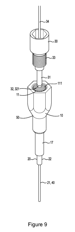
Figure 9 shows a perspective view of a connector of the type illustrated in
Figures 3a, 3b,
and 4, together with a fitting.
Figure 10 shows a chromatography column in fluid connection with a fitting
using an
embodiment of a connector of the present invention.
Figure 11 is a side view of an embodiment of a connector in accordance with
the second
aspect of the present invention.
Figures ha, lib, 11 c and lid are, respectively, a side view, a rear view, a
top view and a
rear perspective view of an embodiment of a connector in accordance with the
second aspect
of the present invention.
Figure 12 is a schematic cross-section of a connector, with the capillary in
situ.
Figure 13 is a schematic cross-section of the connector illustrated in Figure
12, with the
connecting fitting in situ.
CA 03084837 2020-06-05
WO 2019/144199 PCT/AU2019/050061
- 10 -
Detailed Description
In the following detailed description, reference is made to accompanying
drawings which
form a part of the detailed description. The illustrative embodiments
described in the
detailed description, depicted in the drawings and defined in the claims, are
not intended to
be limiting. Other embodiments may be utilised and other changes may be made
without
departing from the spirit or scope of the subject matter presented. It will be
readily
understood that the aspects of the present disclosure, as generally described
herein and
illustrated in the drawings can be arranged, substituted, combined, separated
and designed
in a wide variety of different configurations, all of which are contemplated
in this
disclosure.
As used herein, the singular forms "a," "an," and "the" designate both the
singular and the
plural, unless expressly stated to designate the singular only.
The term "about" and the use of ranges in general, whether or not qualified by
the term
about, means that the number comprehended is not limited to the exact number
set forth
herein, and is intended to refer to ranges substantially within the quoted
range while not
departing from the scope of the invention. As used herein, "about" will be
understood by
persons of ordinary skill in the art and will vary to some extent on the
context in which it is
used. If there are uses of the term which are not clear to persons of ordinary
skill in the art
given the context in which it is used, "about" will mean up to plus or minus
10% of the
particular term.
In addition, where dimensions are described herein, it will be appreciated
that plus or
minus ( ) typical manufacturing tolerances are applicable to those values. As
appreciated
by those in the art, manufacturing tolerances may be determined to achieve a
desired mean
and standard deviation of manufactured components in relation to the ideal
component
profile.
CA 03084837 2020-06-05
WO 2019/144199 PCT/AU2019/050061
- 11 -
The present invention provides a connector for providing a fluid connection
between a
capillary and a fluid conduit, said connector comprising:
a capillary holder for receiving an end of the capillary, said capillary
comprising
inner capillary tubing, wherein the inner capillary tubing of the received end
of the
capillary is located within a compliant material sleeve;
a deformable portion configured for deforming so that the compliant material
of the
sleeve in the capillary holder is deformed to create a seal between the inner
capillary
tubing and the connector; and
a receiving portion configured to receive a fitting at an end of the fluid
conduit;
wherein the capillary holder and the receiving portion are connected so that
the connector
is configured to fluidly connect the capillary and the fluid conduit.
By deforming the deformable portion of the connector to form the seal between
the inner
capillary tubing and the connector, the connector is fixed to the end of the
capillary, thus
forming a capillary assembly. In the capillary assembly of the present
invention, there
may be a connector at either or each end of the capillary.
In a first aspect, the present invention provides a connector for providing a
fluid
connection between a capillary and a fluid conduit, said connector comprising:
a capillary recess for receiving an end of the capillary, said capillary
comprising
inner capillary tubing within a compliant material sleeve;
a deformable portion configured for deforming so that the compliant material
of a
capillary received in the capillary recess is deformed to create a seal
between the inner
capillary tubing and the connector;
a receiving portion configured to receive a fitting at an end of the fluid
conduit;
a connecting passage connecting the capillary recess and the receiving portion
and
configured to fluidly connect the capillary and the fluid conduit.
As noted above, in a second aspect, the connector may not require a connecting
passage. In
addition, in the second aspect, the connector may comprise the compliant
material sleeve,
rather than the capillary. The capillary holder can be configured to receive
the compliant
CA 03084837 2020-06-05
WO 2019/144199 PCT/AU2019/050061
- 12 -
material sleeve so that when the capillary holder receives the end of the
capillary, the inner
capillary tubing is also received by the compliant material sleeve. In this
aspect, the
compliant material of the sleeve received in the capillary holder is deformed
to create a
seal between the inner capillary tubing and the connector.
The term "fluid" as used herein is intended to include liquids and gases, as
well as a
mixture thereof, including emulsions, dispersions and slurries of finely
divided particulates
suspended in a liquid. The nature of the fluid to be conveyed along the fluid
conduit and
the inner capillary tubing will depend upon the particular application in
which the
connector is to be utilised.
As used herein, "capillary" refers to a tube which has a fine internal
diameter. In the
present invention, the capillary comprises inner capillary tubing. In some
embodiments,
such as embodiments of the first aspect of the present invention, the
capillary comprises
inner capillary tubing within a compliant material sleeve. The connector of
the present
invention may be used with capillaries having inner capillary tubing with an
external
diameter of about 0.0001 to about 5 mm, with preferable external diameters of
0.25 to
about 0.5 mm, such as about 0.35 to about 0.38 mm. The lumen of the inner
capillary
tubing (i.e. the bore of the tubing) may have a diameter of 0.01 to about 0.2
mm, such as
about 0.025 to about 0.1 mm, for example about 75
The fluid conduit may be another capillary, which may comprise inner capillary
tubing
with or without a surrounding compliant material sleeve.
The inner capillary tubing may be ceramic glass, borosilicate glass, cladded
fused silica,
fused silica glasses, aluminosilicate glasses, glass-lined stainless steel,
quartz, or metal
such as stainless steel, titanium, nickel, gold, or platinum. For example, in
some
embodiments, the inner capillary tubing may be fused-silica, polyimide coated
fused-
silica, aluminium coated fused-silica or borosilicate glass.
CA 03084837 2020-06-05
WO 2019/144199 PCT/AU2019/050061
- 13 -
When the inner capillary tubing includes a coating, such as when the inner
capillary
tubing is polyimide coated fused silica, the thickness of the coating may be
about
0.001 mm to about 0.5 mm such as about 0.01 mm. The outer diameter of the
coating may
be about 0.1% to about 50% greater than the outer diameter of the underlying
tubing of
the inner capillary tubing, such as about 5%. Thus, in some embodiments, the
capillary
may comprise underlying tubing (such as fused silica), a coating on the
underlying tubing
(such as polyimide) and the compliant material sleeve.
The inner capillary tubing may be rigid or flexible. However, the compliant
material sleeve
will be relatively more compliant than the inner capillary tubing and the
deformable
portion of the connector of the present invention. In particular, deformable
portion and the
compliant material sleeve can be configured for the selected inner capillary
tubing so that,
when the deformable portion of the connector is deformed, the compliant
material is
deformed to create a seal between the inner capillary tubing and the
connector, but the
inner capillary tubing is not crushed or significantly deformed such that
there is an
unacceptable compromise of the fluid flow through the capillary. The
deformation of the
compliant material may be elastic and/or plastic deformation.
Deforming the deformable portion onto the inner capillary tubing in the
absence of the
compliant material sleeve may lead to an unacceptable compromise of the fluid
flow
through the capillary. For example, when the inner capillary tubing forms part
of a
chromatography column, the deformation required to form a high pressure seal
may crush
the inner capillary tubing. In the present invention, the intervening layer of
compliant
material, provide by the sleeve, distributes the load exerted by the deformed
deformable
portion so that a suitable seal can be formed. Thus, the compliant material
can protect the
inner capillary tubing so that the performance of the capillary is maintained
at an
appropriate level. While the thickness of the compliant material may be
reduced in the
region of the deformation of the deformable portion, a layer of compliant
material remains
between the inner capillary tubing and the part(s) of the deformable portion
that have been
deformed. Deforming the compliant material does not displace the compliant
material
from between the inner capillary tubing and the connector so that there is
direct contact of
CA 03084837 2020-06-05
WO 2019/144199 PCT/AU2019/050061
- 14 -
the part(s) of the deformable portion that have been deformed with the inner
capillary
tubing. Thus, in the present invention, the deformable portion may be
configured for
deforming so that the compliant material of the sleeve in the capillary holder
is deformed
to create a seal of interposed compliant material between the inner capillary
tubing and the
connector.
The compliant material may comprise a polymer. The compliant material may
comprise
one or more of: polyethylene terephthalate; polyethylene, such as high density
polyethylene (HDPE) or low density polyethylene (LDPE); polyvinyl chloride;
polypropylene; and polystyrene. The compliant material may comprise a polymer
selected from the group consisting of polyimides, fluoropolymers,
polyaryletherketones
(PAEK) and mixtures thereof. In some embodiments, the compliant material may
comprise a polyaryletherketone, and the polyaryletherketone may be selected
from the
group consisting of polyetherketone (PEK), polyetheretherketone (PEEK) and
polyetherketoneketone (PEKK). In some embodiments, it may be particularly
preferred
for the compliant material to comprise PEEK.
The connector may comprise a metal or alloy that is biocompatible and/or
inert, or a metal
or alloy that is coated with a biocompatible and/or inert material (that,
e.g., may be a
biocompatible and/or inert metal). Biocompatible and/or inert materials are
discussed
further below. The connector may comprise stainless steel, titanium, nickel,
gold, or
platinum. If the connector comprises a metal or alloy coated with a
biocompatible and/or
inert material, the coating can be such that the deformable portion can be
deformed without
exposing the underlying metal or alloy. That is, the deformation of the
deformable portion
may not damage the coating in such a way that its efficacy is substantially
affected.
When used in chromatographic applications, at the junction of the inner
capillary tubing
and the fitting, the material is preferably conductive to allow the
application of the
electrospray voltage for ionisation whilst maintaining minimal dead volume.
That is, the
end of the inner capillary tubing may be surrounded by a conductive material
and/or in
fluid connection with a connecting passage made in a conductive material.
In
CA 03084837 2020-06-05
WO 2019/144199 PCT/AU2019/050061
- 15 -
embodiments where the compliant material sleeve is around the end of the inner
capillary
tubing, the compliant material may be conductive. A conductive material, as
used herein,
refers to an electrically conductive material. The voltage connection is
typically greater
than lkV. Thus, the conductive material may be a material that is electrically
conductive
when subjected to a voltage of greater than lkV.
A suitable conductive compliant material may have an electrical conductivity
of less the
107 0, or about less than 105 O. A suitable conductive compliant material may
have a
specific volume resistance of about 103 12cm to about 105 12cm (measured in
accordance
with DIN EN 61340-2-3, conductive rubber, 23 C, 12% r.h.). A suitable
conductive
compliant material may have a specific surface resistance of about 102 1 to
about 104
(measured in accordance with DIN EN 61340-2-3, 20mm thick sample, conductive
rubber,
23 C, 12% r.h.). The conductive material may be a mixture of a suitable
polymer, such as
the polymers noted above, with carbon nanotubes. In some embodiments, the
compliant
material is conductive PEEK. For example, in some embodiments, the compliant
material
is TECAPEEK ELS nano black from Ensinger GmbH.
If the material at the junction of the inner capillary tubing and the fitting
is not conductive,
an electrically conductive connection may be provided upstream of the
connector. For
example, the electrically conductive connection may be upstream of the fitting
received by
the receiving portion. The electrically conductive connection may be at a
junction with the
fluid conduit connected to the fitting and one or more other fluid conduits.
For example,
the electrically conductive connection may be at a tee-junction with the fluid
conduit
connected to the fitting. The electrically conductive connection may be a
specific
connection provided along the fluid conduit. In some embodiments, the
electrically
conductive connection may be provided at the opposite end of the fluid conduit
to the
fitting or upstream of the fluid conduit, such as at the chromatography
device.
The connector of the present invention may be manufactured as a unitary part.
Typically,
the connector of the first aspect of present invention is manufactured as a
unitary part. As
the connector of the present invention can be a unitary part, it may have a
simpler
CA 03084837 2020-06-05
WO 2019/144199 PCT/AU2019/050061
- 16 -
construction than other fittings for connecting capillaries to fluid conduits
and, as such,
may be produced more economically. Accordingly, in some embodiments, the
connector
of the present invention may be advantageously used for disposable/single-use
components. In particular, the capillary assembly of the present invention may
be a
disposable or single-use component.
In some embodiments, such as those of the second aspect, the connector may
comprise the
compliant material sleeve, rather than the capillary. In such embodiments, the
compliant
material sleeve is provided as a separate part of the connector. Preferably
the remainder of
the connector is manufactured as a unitary part.
In some embodiments, it is desirable that the connector (as well as other
components, such
as the capillary) is made of a biocompatible and/or inert material. In some
embodiments,
the material may be "bioinert". That is, the selected material may combine
biocompatibility with biological or biochemical substances and inertness
against
aggressive chemical environment such as extreme pH values. Biocompatibility
may be
denoted as the capability to exist in harmony with biological material such as
macro-
molecules like proteins or genes. It may also denote the quality of not having
toxic effects
on biological systems. An inert material is ideally inert against extreme pH-
values such as
pH-values in the entire range of 1 to 14. That is, even in the presence of a
strongly ionizing
chemical environment, an inert material may not deteriorate, or at least not
substantially be
deteriorated. Thus, an inert material preferable does not generate a
meaningful amount of
ions. A meaningful amount of ions is an amount that may harm or negatively
affect, for
example, monoclonal antibodies, proteins, etc., or components of a
chromatography
system such as chromatographic columns or mass spectroscopy equipment.
It can be desirable for the material around the end of the inner capillary
tubing to be the
compliant material, as compliant materials may be more bioinert than the
material selected
for the connector.
CA 03084837 2020-06-05
WO 2019/144199 PCT/AU2019/050061
- 17 -
When the end of the capillary is received in the capillary holder of the
connector, the
compliant material sleeve may be located such that the sleeve fills the
capillary holder so
that it contacts the internal surface(s) of the holder. In some embodiments,
the capillary
holder is a cylindrical bore in one end of the connector that extends to the
receiving portion
of the connector. The capillary holder may comprise a sleeve section
configured for
receiving and locating the compliant material sleeve. The sleeve section may
be a section
having a larger diameter than the remainder of the capillary holder.
The compliant material sleeve may be inserted into the sleeve section via the
receiving
portion. Once the sleeve is located in the sleeve section, the sleeve may
provide an end
face to the first part of the capillary holder and a compliant connecting face
at the end of
the receiving portion. Thus, the compliant material sleeve will be configured
such that,
when located in the sleeve section and after the deformable portion is
deformed, a fitting
received by the receiving portion will contact the compliant connecting face
so that there is
a good fluid connection between the fluid conduit and the passage going
through the
sleeve.
If the compliant material sleeve does not contact all walls of the capillary
holder, or the
sleeve section of the holder, when it is received into the recess, it is
preferable that, after
the deforming of the deformable portion, the compliant material is deformed so
that the
capillary fills the holder or the sleeve section to form a good seal.
Accordingly, it can be desirable for the external dimensions of the compliant
material
sleeve to closely match the internal dimensions of the capillary holder before
the
deformable portion is deformed. It may be preferred that the there is minimal
clearance
between the compliant material sleeve and the capillary holder, or at least
the sleeve
section of the holder, so that the sleeve can be received by the holder
without damaging
the compliant material or the inner capillary tubing. In such embodiments, the
clearance
between the compliant material sleeve and the wall(s) of the capillary holder
extending in
the longitudinal direction of the sleeve may be about 0.001 mm to about 0.5
mm, such as
about 0.01 mm to about 0.05 mm. In some embodiments, the capillary holder may
be
CA 03084837 2020-06-05
WO 2019/144199 PCT/AU2019/050061
- 18 -
sized so that the capillary may still be readily received, but where it is
slightly force-fit so
there is some deformation of the compliant material sleeve during insertion.
Typically, in the first aspect of the invention, when the end of the capillary
is received in
the capillary recess of the connector, the capillary substantially fills the
recess so that it
contacts internal surfaces of the recess. If the capillary does not contact
all walls of the
capillary recess when it is received into the recess, it is preferable that,
after the deforming
of the deformable portion, the compliant material is deformed so that the
capillary fills the
recess to form a good seal. Furthermore, the deformation of the compliant
material by the
deforming of the deformable portion may be such that the compliant material is
urged
against the end face of the capillary recess so as to further enhance the
sealing around the
inner capillary tubing at the interface with (or in the region of) the
connecting passage. It is
particularly desirable that there is good contact around the interface of the
capillary recess
and the connecting passage to minimise the risk of any dead volume being
produced.
Accordingly, it can be desirable for the external dimensions of the compliant
material
sleeve to closely match the internal dimensions of the capillary recess before
the
deformable portion is deformed. It may be preferred that the there is minimal
clearance
between the capillary and the capillary recess so that the capillary can be
received by the
recess without damaging the compliant material or inner capillary tubing. In
such
embodiments, the clearance between the compliant material sleeve and the
wall(s) of the
capillary recess extending in the longitudinal direction of the capillary may
be about
0.001 mm to about 0.5 mm, such as about 0.01 mm to about 0.05 mm. In some
embodiments, the capillary recess may be sized so that the capillary may still
be readily
received by the recess, but where it is slightly force-fit so there is some
deformation of the
compliant material sleeve during insertion. In such embodiments, the end of
the capillary
may be received in the capillary recess of the connector so that it fills and
contacts all
internal surfaces of the recess.
The compliant material sleeve may be separate from the inner capillary tubing,
such as a
sheath, or a coating applied to the inner capillary tubing. The thickness of
the compliant
CA 03084837 2020-06-05
WO 2019/144199 PCT/AU2019/050061
- 19 -
material sleeve may be about 0.1 mm to about 5 mm, such as about 0.58 mm. The
outer
diameter of the compliant material sleeve may about 50% to about 1000% greater
than the
outer diameter of the inner capillary tubing, such as about 400% to about
500%, for
example about 433%.
The compliant material sleeve should be of a sufficient length that it can be
deformed by the
deformation of the deformable portion to create a seal between the inner
capillary tubing
and the connector. In some embodiments, the compliant material sleeve extends
along the
entire length of the capillary or substantially the entire length.
Alternatively, the compliant
material sleeve may extend along only part of the capillary. The compliant
material sleeve
may extend along the entire length of the capsule holder or along only part of
the length. In
the first aspect of the present invention, the compliant material sleeve will
often extend along
the capillary for at least the length that is received in the capillary
recess. However, in some
embodiments, the compliant material sleeve is shorter than the capillary
recess. In such
embodiments, the compliant material sleeve will, ideally, be located within
the capillary
recess so that it abuts the end face of the capillary recess, or is close to
the end face, so as to
minimise any dead volume.
In some embodiments, before the deformable portion has been deformed, it is
desirable that
the inner capillary tubing be capable of being displaced along the compliant
material sleeve
so that it can be caused to extend beyond the end of the compliant material
sleeve. In
particular, in the first aspect, the connecting passage may be configured to
receive the inner
capillary tubing. That is, the end of the inner capillary tubing can be
inserted into the
connecting passage before the deformable portion is deformed to create the
seal. Typically,
the connecting passage will be configured to permit the end portion of the
inner capillary
tubing to be received within the connecting passage with the minimum tolerance
so as to
minimise any potential dead volume around the inner capillary tubing.
Thus, in some embodiments of the capillary assembly, part of the inner
capillary tubing
extends into the connecting passage of the connector. In some of those
embodiments, the
inner capillary tubing extends to an intermediate point along the connecting
passage. In
CA 03084837 2020-06-05
WO 2019/144199 PCT/AU2019/050061
- 20 -
some other embodiments, the inner capillary tubing extends along full length
of the
connecting passage. In some embodiments, the connecting passage extends
between an end
face of the capillary recess and a connecting face of the receiving portion;
and the inner
capillary tubing received in the connecting passage extends therethrough until
the
connecting face. It will be appreciated that the end face of the capillary
recess is the face
into which one end of the connecting passage is formed. Similarly, the
connecting face of
the receiving portion is the face into which the other end of the connecting
passage is
formed.
For such embodiments, it can be desirable for the dimensions of the connecting
passage to
closely match the inner capillary tubing so as to minimise or eliminate any
dead volume in
the region between the connecting passage and inner capillary tubing. In
addition, the
dimensions of the connecting passage will be selected so that the desired
inner capillary
tubing can be inserted into the connecting passage without damaging the
tubing.
In some embodiments, the connecting passage may be configured to receive the
inner
capillary tubing and part of the compliant material sleeve. The connecting
passage and the
part of the compliant material sleeve to be received may be mutually
configured so that a
good seal is formed by the compliant material between the wall(s) of the
connecting
passage and the inner capillary tubing so as to minimise any dead volume. The
received
part of the compliant material sleeve may extend through the connecting
passage to the
same point as the inner capillary tubing. Alternatively, the received part of
the sleeve and
the inner capillary tubing may terminate at different points through the
connecting passage.
Typically, to minimise the dead volume, if the received part and the capillary
terminate at
different points, the received part will extend further into the connecting
passage than the
inner capillary tube.
In some embodiments, the compliant material sleeve extends slightly beyond the
connecting face so as to form a compliant connecting face that can facilitate
a good seal
being formed with the fitting.
CA 03084837 2020-06-05
WO 2019/144199 PCT/AU2019/050061
-21 -
Alternatively, the connecting passage may have a bore narrower than the inner
capillary
tubing. The inner capillary tube will ideally abut the end face of the
capillary recess so as
to minimise any dead volume. In addition, it is preferable for the volume of
the connecting
passage to be low as possible to minimise the dead volume produced by it. It
will be
appreciated that the length and/or diameter of the connecting passage can be
selected so at
to minimise its volume. The connecting passage may have a length of about 0.1
mm to
about 5 mm, such as about 1 mm. The bore (i.e. diameter) of the connecting
passage may
be about 0.01 mm to about 0.4 mm, such as about 0.025 mm. The connecting
passage may
have the minimum diameter that does not present an unacceptable risk of being
clogged
during use.
A connecting passage with a desirably fine bore may be manufactured by laser
drilling.
The internal diameter of the fluid conduit may be smaller than the connecting
passage.
Alternatively, the connecting passage may be narrower than the fluid conduit.
In some embodiments, the connector is configured so that the ends of the
capillary and fluid
conduit engaged by the connector are arranged so that they are co-axial. If
the capillary and
fluid conduit are offset from each other, the offset should be such that the
performance of
the connector and the fluid communication between the capillary and fluid
conduit are not
unacceptably adversely affected.
In some embodiments, the connector is configured so that the connecting
passage and the
ends of the capillary and fluid conduit engaged by the connector are arranged
so that they
are co-axial. However, in some embodiments, it may be acceptable for the axis
of one or
more of the connecting passage and the ends of the capillary and fluid conduit
engaged by
the connector to be offset from one or both of the other axes. As noted above,
the offset
should be such that the performance of the connector and the fluid
communication between
the capillary and fluid conduit are not unacceptably adversely affected.
CA 03084837 2020-06-05
WO 2019/144199 PCT/AU2019/050061
- 22 -
As noted above, the deformable portion is configured for deforming so that the
compliant
material of the sleeve received in the capillary holder is deformed to create
a seal between
the inner capillary tubing and the connector. The deformable portion can
deform such that
the size and/or shape of the capillary holder is changed. By altering the size
and/or shape
of the capillary holder, the compliant material sleeve may be deformed such
that it is urged
against wall(s) of the holder and pressed onto the inner capillary tubing so
that a seal
between the inner capillary tubing and the connector is formed. It is
particularly desirable
for there to be a good seal at the end of the inner capillary tubing so as to
minimise the risk
of producing a dead volume.
The seal that is formed may be able to withstand high fluid pressures, such as
those
typically encountered in chromatographic applications. The seal may be able to
withstand
pressures of at least 50 1ViPa, such as at least 100 1ViPa. The seal may be
able to withstand
pressures of up to about about 345 1ViPa (about 50,000 psi), such as about 138
1ViPa (about
20,000 psi). Furthermore, the seal may be able to withstand repeated cycles,
such as up to
1000 cycles, or up to 10,000 cycles, of pressures of up to about 138 1ViPa
(about 20,000
psi), such as pressures up to about 1171ViPa (about 17,000 psi) .
In the first aspect of the present invention, the deformable portion of the
connector of the
present invention is configured for deforming so that the compliant material
of a capillary
received in the capillary recess is deformed to create a seal between the
inner capillary
tubing and the connector. The deformable portion can deform such that the size
and/or
shape of the capillary recess is changed. By altering the size and/or shape of
the capillary
recess, the compliant material sleeve may be deformed such that it is urged
against faces of
the capillary recess, in particular the end face and the region near the end
face, and pressed
onto the inner capillary tubing, so that a seal between the inner capillary
tubing and the
connector is formed. As a result of the deformation, the compliant material
may be urged
against the end face of the capillary recess so as to further enhance the
sealing around the
inner capillary tubing at the interface with (or in the region of) the
connecting passage. To
minimise the risk of any dead volume being produced, it is particularly
desirable that there is
good contact around the interface of the capillary recess and the connecting
passage.
CA 03084837 2020-06-05
WO 2019/144199 PCT/AU2019/050061
- 23 -
Typically, deformation of the deformable portion reduces the volume of the
capillary
holder, such as the capillary recess. Accordingly, in some embodiments, the
deformable
portion is a compressible portion configured for compressing so that the
compliant
material received in the capillary holder is deformed to create a seal between
the inner
capillary tubing and the connector. In some embodiments, the deformable
portion is a
crimpable portion configured for crimping so that the compliant material
received in the
capillary holder is deformed to create a seal between the inner capillary
tubing and the
connector. In some embodiments of the first aspect, the deformable portion is
a crimpable
portion configured for crimping so that the compliant material of a capillary
received in the
capillary recess is deformed to create a seal between the inner capillary
tubing and the
connector. The radial compression effected by the crimping can compress the
connector
onto the compliant material sleeve so that it is deformed such that it is
urged against the
faces of the capillary recess and compressed onto the inner capillary tubing,
and a seal
between the inner capillary tubing and the connector is formed.
The deformable portion may extend along part of the length, or along the full
length, of the
capillary holder, e.g. the capillary recess. In some embodiments, the
capillary holder, e.g.
the capillary recess, extends along the full length of the deformable portion
and into an
intermediate region of the connector.
It may not be necessary to deform the entire deformable portion so as to
create a seal.
Instead, only part of the deformable portion may need to be deformed so as to
form an
effective seal. For example, the deformable portion may only require deforming
along
about 0.5 mm to about 10 mm, for example about 2 mm to about 3 mm, such as
about 3 mm,
of the length of the deformable portion in order to form an effective seal.
The deformable
portion may only require deforming along about 6% to about 90%, such as about
40% of the
length of the deformable portion in order to form an effective seal. In some
embodiments,
the length of the deformable portion may be less than about 5 mm, such as less
than about
4 mm, for example, about 2 to about 3 mm.
CA 03084837 2020-06-05
WO 2019/144199 PCT/AU2019/050061
- 24 -
In embodiments where the deformable portion is a crimpable portion, the
crimpable portion
may only require crimping along about 0.5 mm to about 10 mm, for example about
2 mm to
about 3 mm, such as about 3 mm, of the length of the crimpable portion in
order to form an
effective seal. In some embodiments, the length of the crimpable portion may
be less than
about 5 mm, such as less than about 4 mm, for example, about 2 mm to about 3
mm.
The wall thickness of the deformable portion may be about 0.1 mm to about 5
mm, such as
about 0.5 mm to about 0.7 mm. In some embodiments, the outer diameter of the
deformable portion is about 1 to about 100%, such as about 31% greater than
the outer
diameter of the compliant material sleeve or the diameter of the capillary
holder. Thus, in
some embodiments of the first aspect, the outer diameter of the deformable
portion is
about 1 to about 100%, such as about 31%, greater than the outer diameter of
the
compliant material sleeve of the capillary or the diameter of the capillary
recess. As noted
above, it is desirable for the external dimensions of the compliant material
sleeve to
closely match the internal dimensions of the capillary holder, such as the
capillary recess.
Deforming, such as crimping, may reduce the outer diameter of the deformed
region of the
deformable portion by about 2% to about 25%, such as about 7% to about 15%,
for
example about 9% to about 10%.
After deforming, the seal may be such that the capillary cannot be pulled out
of the
connector even when loads of up to 20 kg are applied. In some embodiments, the
seal may
be such that the inner capillary tubing will break before the capillary is
pulled out of the
connector.
Embodiments of the capillary assembly of the present invention may be able to
withstand
pressures of up to about about 345 1\413a (about 50,000 psi), such as about
138 1\413a (about
20,000 psi). Furthermore, embodiments of the capillary assembly of the present
invention
may be able to withstand repeated cycles, such as up to 1000 cycles, or up to
10,000
cycles, of pressures of up to about 138 1\413a (about 20,000 psi), such as
pressures up to
CA 03084837 2020-06-05
WO 2019/144199 PCT/AU2019/050061
- 25 -
about 117 1ViPa (about 17,000 psi). Embodiments of the capillary assembly may
be able to
withstand pressures of at least 50 MPa, such as at least 100 MPa.
In some embodiments, the seal may be such that there will be no leakage at
pressures
encountered during typical use of the capillary. For example, in embodiments
where the
capillary forms part of a chromatographic system, the capillary assembly of
the present
invention may be able to withstand pressures of up to about 138 1ViPa (about
20,000 psi),
such as pressures up to about 117 1ViPa (about 17,000 psi), without leakage.
As noted
above, in some embodiments, the capillary may form part of a chromatography
column. In
some embodiments, the maximum operating pressure for the chromatography
columns
may be up to about 138 1ViPa (about 20,000 psi), such as pressures up to about
120 1ViPa, e.g
about 117 MPa (about 17,000 psi).
The receiving portion of the connector is ideally configured so that there is
a sealed
.. engagement between the fitting and the connector. This sealed engagement
should enable
the effective fluid connection of the capillary and the fluid conduit. In
addition, it is
desirable for that sealed engagement to be such that any dead volume between
the fluid
conduit and the capillary is minimised or prevented.
The sealed engagement may be such that the fitting received in the receiving
portion of
may be able to withstand pressures of up to about 138 1ViPa (about 20,000
psi), such as
pressures up to about 120 1ViPa, e.g. about 117 1ViPa (about 17,000 psi),
within the fluid
conduit, without significant leakage. Furthermore, some embodiments may be
able to
withstand repeated cycles, such as up to 1000 cycles, or up to 10,000 cycles,
of pressures
of up to about 138 1ViPa (about 20,000 psi), such as pressures up to about 117
1ViPa (about
17,000 psi) .
The sealed engagement may be such that there will be no leakage at pressures
encountered
during typical use of the fitting and fluid conduit. For example, in
embodiments where the
fitting and fluid conduit forms part of a chromatographic system, the sealed
engagement
between the fitting and the connector of the present invention may be able to
withstand
CA 03084837 2020-06-05
WO 2019/144199 PCT/AU2019/050061
- 26 -
pressures of up to about 138 1\,/fPa (about 20,000 psi), such as pressures up
to about 120
1\,/fPa, e.g. about 1171\,/fPa (about 17,000 psi), without leakage.
The receiving portion can be configured to receive a variety of fittings for
fluid conduits
that are known in the art, particularly those known in the art of fittings for
fluid conduits of
chromatography systems. The shape and configuration of the receiving part will
typically
be selected to optimise the engagement between the connector and the fitting.
Thus, the
receiving portion can be considered to be a female recess configured for the
complementary male fitting. In some embodiments, the fluid conduit is another
capillary
and the fitting may be a commercially available fitting for a capillary.
Embodiments of the present invention are particularly suited to receiving
fittings with a
sealing element at the tip. For example, the fitting may be a commercially
available fitting
for a capillary, such as a Thermo ScientificTM ViperTM or nanoViperTM fitting,
or an IDEX
Health & Science Marvel XTM or Marvel XactTM fitting. The fitting and fluid
conduit may
be a connector unit for connecting capillaries such as that described in US
Patent Publication
No. 2014/0145437, the contents of which are incorporated herein by reference.
In embodiments where the connector is configured for receiving a fitting with
a sealing
element at the tip of the fitting, the receiving portion may be configured so
that at least part
of the sealing element contacts a compliant connecting face formed by the
compliant
material sleeve to form a seal around passage in which the end of the inner
capillary tubing
is located. In embodiments of the first aspect, where the connector is
configured for
receiving a fitting with a sealing element at the tip of the fitting, the
receiving portion may
be configured so that at least part of the sealing element contacts the
connecting face to
form a seal around the connecting passage. In some embodiments, the sealing
element is
an annular sealing element provided on the outer side of the fluid conduit. In
some
embodiments, the sealing element may include a section which projects out of
the capillary
at the face of the end of the capillary.
CA 03084837 2020-06-05
WO 2019/144199 PCT/AU2019/050061
- 27 -
The receiving portion may comprise a sealing recess into which the tip of the
fitting may
be inserted. In some embodiments, the receiving portion is such that the
sealing element
may be inserted together with the end of the fluid conduit into the sealing
recess and an
axial force can be exerted thereon such that, as a result of plastic or
elastic deformation of
the sealing element, sealing of the fitting is attained in the region of the
connecting face,
whereby the formation of a dead volume is minimised of prevented. During the
dismounting of the fitting, the sealing element may also be pulled out of the
sealing recess
in a relatively simple manner together with the capillary.
In some embodiments, the connecting face of the sealing recess is formed by
inserting the
compliant material sleeve into the capillary holder. Thus, the connecting face
of the sealing
recess is a compliant connecting face. The receiving portion may be such that
the fitting,
optionally including a sealing element, may be inserted into the sealing
recess and an axial
force can be exerted thereon such that, as a result of plastic or elastic
deformation of the
compliant connecting face, sealing of the fitting is attained around the
passage in which the
inner capillary tubing is located, whereby the formation of a dead volume is
minimised of
prevented.
In some embodiments, the tip of the fitting fills the volume of the sealing
recess as
completely as possible, so as to minimise or avoid the formation of a dead
volume. The
fitting may be received by the receiving portion so as to press the sealing
element against
the surface of the receiving portion so that the sealing element deforms
against the
connecting face and/or the wall(s) of the sealing recess at the periphery of
the connecting
face.
The receiving portion can comprise engagement components that are
complementary to the
engagement components of the fitting. The complementary engagement components
can
be used to receiving the fitting in the receiving portion and retain it so
that so that there is a
sealed engagement between the fitting and the connector. As noted above, this
sealed
engagement should enable the effective fluid connection of the capillary and
the fluid
conduit. In some embodiments, the engagement component may be an internal
threaded
CA 03084837 2020-06-05
WO 2019/144199 PCT/AU2019/050061
- 28 -
section. That is, the receiving portion often comprises an internal threaded
section
configured to engage a complementary external threaded section of the fitting.
In such
embodiments, the fitting may be screwed into the receiving portion. In
embodiments
where the fitting has a sealing element at the tip, the fitting may be screwed
into the
receiving portion until the sealing element contacts and deforms against the
surface of the
receiving portion so that there is a sealed engagement. In embodiments where
receiving
portion has a compliant connecting face, the fitting may be screwed into the
receiving
portion until the tip contacts and deforms against and/or deforms the
compliant material of
the receiving portion so that there is a sealed engagement.
The receiving portion of the connector may comprise alternative or additional
engagement
components to a complementary threaded section so that the desired fitting can
be used.
As noted above, the connector and capillary assembly of the present invention
may be used
in chromatographic systems. In some embodiments, the capillary forms part of a
chromatography column. Various configurations of chromatography columns
utilising a
capillary will be known to those skilled in the art. It will be apparent to
those skilled in the
art, in view of the present disclosure, that a variety of column
configurations can be used
with the connector and capillary assembly of the present invention.
The chromatography column may be an ion-exchange, normal phase or reverse
phase
chromatography column. The stationary phase of the column may be surface
modified
silica beads, or coated polymeric beads. The stationary phase of the column
may include
octadecyl carbon chain (C18)-bonded silica (USP classification L1), C8-bonded
silica
(USP classification L7), pure silica (USP classification L3), cyano-bonded
silica (USP
classification L10) and phenyl-bonded silica (USP classification L11). The
stationary
phase may have a particle size of 1.3 - 5 [tm, for example 1.6 [tm. The column
may have a
pore size of 80 ¨ 400A, for example 120 A.
CA 03084837 2020-06-05
WO 2019/144199 PCT/AU2019/050061
- 29 -
The chromatography column may be capable of operating at temperatures of up to
65 C
(low pH). In some embodiments, the chromatography column may have pH stability
for
pH-values in the range of 1 to 8.
The chromatography column may be about 150 to about 750 mm long, for example
about
250 mm long.
In some embodiments of the capillary assembly, the capillary forms part of a
chromatography column comprising an integrated electrospray emitter.
Electrospray
ionization is a technique used in mass spectrometry to produce ions using an
electrospray
in which a high voltage is applied to a liquid to create highly-charged
droplets that, under
evaporation, create ions representative of the species contained in a sample
solution.
Capillary columns may be prepared either completely packed throughout its
length with a
stationary phase or with the stationary phase material occupying only part of
the capillary,
typically in the vicinity of its tip. In the case of the latter, the capillary
column is often
fitted with a frit. The term 'frit' as used herein refers to a matrix material
which may be a
solid, or a porous, or microporous material used to retain stationary phase
material within
a separation column for performing pressure-driven liquid chromatography.
The choice and volume of the stationary phase material can vary depending on
the
complexity and volume of the sample, and the goal of the separation.
There are different approaches for packing fritted capillary columns. One such
method is
referred to as the dry packing method. In accordance with this method, dry
packing
material, such as glass, silica, polymeric powder or metallic powder, is
forced into one
end of capillary column. The particulate materials are rapidly vibrated as
they are loaded
into the tube through a funnel. A second method is the slurry packing method
where a
liquid comprising suspended particles of packing material, is forced under
pressure into
the proximal end of the tube, and pumped until the slurry reaches the frit at
the distal end
of the tube. The frit serves to filter the particulate packing material from
the liquid, which
CA 03084837 2020-06-05
WO 2019/144199 PCT/AU2019/050061
- 30 -
is also known as the mobile phase. The mobile phase thus passes through the
fit and out
of the tube, while the solid packing particles remain behind the frit. Slurry
packing
normally requires the use of high pressures (> 6.9 MPa, > 1000 psi) in order
to generate a
high flow rate of mobile phase and resultant high impact velocity of the
incoming
particles. This high velocity forms a tightly packed bed.
In some embodiments, the capillary may be packed before the connector of the
present
invention is fixed (by deformation of the deformable portion) onto the end of
the capillary.
In some other embodiments, the connector may be fixed on to the end of the
capillary
before packing the column and the connector can be used to facilitate the
packing process.
Figure 1 is a schematic cross-section of an embodiment of a connector 10 in
accordance with
the present invention, and Figure 2 is a schematic cross-section of this
embodiment of the
connector 10 with the capillary 20 in situ. Thus, Figure 2 illustrates a
capillary assembly 50
in accordance with the present invention. In Figure 2, the inner capillary
tubing 21 of the
capillary 20 is not shown in cross-section. The illustrated embodiment of the
connector 10 is
one suitable for use in chromatographic systems.
The connector 10 includes a receiving portion 11 that is configured to receive
a fitting at an
end of a separate fluid conduit (not shown). In this schematic representation
of the connector
10, engagement components on the receiving portion 11 (for receiving the
fitting in the
receiving portion and retaining it there) have been omitted. The size, shape
and
configuration of the receiving portion 11, in particular the inner dimensions
of the receiving
portion 11, will be determined by the size, shape and configuration of the
fitting of the fluid
conduit.
The embodiment shown in Figure 1 is an embodiment of the connector 10 that is
configured
for use with a fitting having a tip with a sealing element on the end, such as
a Thermo
ScientificTM ViperTM or nanoViperTM fitting or the connector unit described in
US Patent
Publication No. 2014/0145437. Thus, the receiving portion 11 defines a sealing
recess 12
into which the tip of the fitting can be inserted such that it abuts the
connecting face 13 50
CA 03084837 2020-06-05
WO 2019/144199 PCT/AU2019/050061
- 31 -
that there is a suitable seal between the connector 10 and the fluid conduit.
The connecting
face 13 is an annular face surrounding one end of the connecting passage 14.
Typically, the
receiving portion 11 is configured such that the fluid conduit is located so
that it is co-axial
with the connecting passage 14 and the capillary holder 100 (which in this
embodiment is a
capillary recess 15) so that, when the capillary 20 (shown in Figure 2) is
received in the
capillary recess 15, the inner capillary tubing 21 is aligned with the
connecting passage 14
and the fluid conduit. The sealing recess 12 and the capillary recess 15 both
extend into the
intermediate region 18 of the connector 10.
Figure 2 shows the capillary 20 including the compliant material sleeve 22 and
the inner
capillary tubing 21 received by the capillary recess 15. The capillary 20 may
be provided
with the compliant material sleeve 22 such that the sleeve 22 extends at least
along the length
of the capillary recess 15. For example, the sleeve 22 may be provided along
substantially
the entire length of the inner capillary tubing 21. However, to minimise or
substantially
eliminate any dead volume between the fitting of the fluid conduit (not shown)
and the inner
capillary tubing 21, the inner capillary tubing 21 extends at least part-way
and preferably
along the entire length (as shown in Figure 2) of the connecting passage 14.
The compliant
material sleeve 22 is arranged so that it abuts the end face 16 of the
capillary recess 15. The
end face 16 is an annular face surrounding the end of the connecting passage
14 that
interfaces with the capillary recess 15.
The connector 10 includes a deformable portion 17. In this illustrated
embodiment, the
deformable portion 17 is a crimpable portion 17, and it will be denoted as
such in the
following description. The crimpable portion 17 is a crimpable sleeve that
surrounds the
capillary 20. The wall thickness of the crimpable portion 17 and the
dimensions of the
capillary recess 15 will be selected so that the capillary recess 15 may
accommodate the
capillary 20 when the crimpable portion 17 is uncrimped, but that when the
crimpable
portion 17 is crimped the compliant material sleeve 22 deforms so that a seal
is formed
between the inner capillary tubing 21 and the connector 10 by the compliant
material sleeve
22.
CA 03084837 2020-06-05
WO 2019/144199 PCT/AU2019/050061
- 32 -
It may not be necessary to crimp the entire crimpable portion 17 so as to
create a seal.
Instead, only part of the crimpable portion 17 may need to be crimped so as to
form an
effective seal. For example, the crimpable portion 17 may only require
crimping along a
length of 2 to 3 mm in order to form an effective seal. The deformation of the
compliant
material by the crimping of the crimpable portion 17 may be such that the
compliant material
is urged against the end face 16 of the capillary recess 15 so as to further
enhance the sealing
around the inner capillary tubing 21.
Figures 3a and 3b show side and end views of an embodiment of the connector 10
in
accordance with the present invention. The connector 10 is configured for use
with a fitting
having a tip with a sealing element on the end, such as a Thermo ScientificTM
ViperTM or
nanoViperTM fitting or the connector unit described in US Patent Publication
No.
2014/0145437. In Figures 3a and 3b, hidden features are shown in broken lines.
The overall length of the connector 10 may be about 5 mm to about 100 mm, for
example,
about 15 mm to about 50 mm, for example about 23.3 mm. Dimension A of the
receiving
portion 11 may be about 4 mm to about 12 mm, for example about 6.76 mm.
Dimension B
may be about 1 mm to about 10 mm, for example about 3.04 mm. Angle E may be
about
100 to about 90 , for example about 19.49 .
The receiving portion 11 of this embodiment of the connector 10 includes an
internal
threaded section 111. The internal threaded section 111 is configured such
that the fitting of
the fluid conduit (not shown) can be secured into position using a
complementary external
threaded section on the fitting. The length of the internal thread 111
(Dimension J) may be
about 3 to about 12 mm, for example about 6.21 mm. This embodiment of the
connector 10
includes a sealing recess 12 with an annular connecting face 13 of which
Dimension F may
be about 0.4 to about 6.5 mm, for example about 1.7 mm, and Dimension K may be
about
0 mm to about 10 mm, for example about 1.95 mm.
CA 03084837 2020-06-05
WO 2019/144199 PCT/AU2019/050061
- 33 -
The connecting passage 14 of this embodiment is located within the
intermediate region 18
of the connector 10. In addition, the sealing recess 12 and the capillary
holder 100 (which in
this embodiment is the capillary recess 15) both extend into the intermediate
region 18 of the
connector 10. The connecting passage 14 connects the capillary recess 15 to
the sealing
recess 12 of the receiving portion 11. The connecting passage 14 may have a
bore diameter
(Dimension M) of from about 0.0001 to 5 mm, for example about 0.35 to about
0.4 mm,
such as e.g. about 0.37 mm. The size and shape of the connecting passage 14
will be
selected based upon the size and shape of the inner capillary tubing 21.
Typically, the
connecting passage 14 will be configured permit the inner capillary tubing 21
selected to be
received within the connecting passage 14 with the minimum tolerance so as to
minimise
any potential dead volume around the inner capillary tubing 21. The connecting
passage 14
may have a length (Dimension L) of about 0.1 to about 20 mm, for example about
1 mm.
The intermediate region 18 may have a length (Dimension C) of about 1 mm to
about
30 mm, for example about 5.5 mm. The diameter of the intermediate region 18
can vary
along its length. Dimension G may be from about 2 mm to 20 mm, for example
about 3 mm
to about 6 mm, such as about 4 mm. The capillary recess 15 terminates at the
end face 16
and may have a length (Dimension N) of about 3 mm to about 50 mm, for example
about
10.8 mm. The diameter (Dimension I) of the capillary recess 15 may be from
about
0.25 mm to about 6.3 mm, for example about 1.5 mm to about 1.65 mm, such as
about
1.59 mm.
In this illustrated embodiment, the deformable portion 17 is a crimpable
portion 17, and it
will be denoted as such in the following description. The diameter (Dimension
H) of the
crimpable portion 17 may be from about 0.5 mm to about 20 mm. Typically, the
diameter of
the crimpable portion 17 will be about 30% to about 32% larger than the
diameter of the
capillary recess 15.
In this embodiment of the connector 10, the receiving portion 11 includes a
grippable portion
112 that, as shown in Figure 3b, has a hexagonal cross-section. The grippable
portion has
been configured with the hexagonal cross-section so that it may be engaged
using a tool. A
CA 03084837 2020-06-05
WO 2019/144199 PCT/AU2019/050061
- 34 -
variety of alternative cross-section shapes may be used in other embodiments
of the
grippable portion 112. The cross-sectional shape and surface finish of the
grippable portion
112 may be selected to facilitate gripping of the portion so as to enable the
fitting of the fluid
conduit to be readily screwed into the connector 10 or removed from the
connector 10. In
embodiments with a hexagonal cross-section, Dimension 0 may be about 2 mm to
about
20 mm, for example about 6 mm.
Figure 4 shows a perspective view a capillary assembly 50 comprising a
connector 10 of the
embodiment illustrated by Figures 3a and 3b. In the view shown in Figure 4,
the positioning
of the capillary 20, including the inner capillary tubing 21 and the compliant
material sleeve
22, within the connector 10 is shown. In Figure 4, it can be seen that the
inner capillary
tubing 21 extends along and passes through the capillary recess 15 (i.e.
capillary holder 100)
into the connecting passage 14. The arrows of Figure 4 denote the radial
compression that
occurs when the crimpable portion 17 is crimped.
Figure 5 is a schematic cross-section of a connector 10 and a capillary
assembly 50 as
described above with reference to Figures 1 and 2, with a fitting 30 of a
fluid conduit 34
being received by the receiving portion 11. In this figure, the fitting 30 and
fluid conduit 34
are shown as a silhouette. The fitting 30 includes a tip 31 with an end 32 and
a sealing
portion (not shown) is formed at the tip. When the tip is received by the
sealing recess 12,
such that the end 32 abuts the connecting face 13, a seal with little to no
dead volume
between the end of the fitting and the connecting face 13 may be formed so
that there is little
to no dead volume between the end of the fluid conduit 34 and the connector
10. Also, to
minimise dead volume the inner capillary tubing 21 extends through the
capillary holder 100
(the capillary recess 15) and the connecting passage 14 so that it ends at the
connecting face
13. Ideally, the fluid conduit 34 and the inner capillary tubing 21 meet at
the connecting face
13. By being located within the connecting passage 14, the end portion of the
inner capillary
tubing 21 is protected from being damaged or crushed by contact with the
fitting 30 so that a
reliable connection can be formed with little or no dead volume between the
capillary 20 and
the fluid conduit 34.
CA 03084837 2020-06-05
WO 2019/144199 PCT/AU2019/050061
- 35 -
The positioning of the inner capillary tubing 21 such that it extends all the
way through the
connecting passage 14 is shown in further detail in Figure 6. Figure 6
illustrates the
positioning of the inner capillary tubing 21 such that it extends through the
connecting
passage 14 and is brought in line with the connecting face 13. As described
above, the
compliant material sleeve 22 of the capillary 20 is located within the
capillary holder 100
(the capillary recess 15) such that it typically abuts the end face 16 of the
capillary recess 15.
In some alternative embodiments, the end portion of the capillary tubing 21
may extend only
part-way along the connecting passage 14. In such embodiments, a minor dead
volume will
be produced between the end of the inner capillary tubing 21 and the fluid
conduit 34.
However, the size of the dead volume should not be such that the dead volume
unduly
comprises chromatographic system performance. As noted above, it is desirable
to minimise
or eliminate any dead volume.
Figure 7 shows an expanded view of the connecting passage 14 of an alternative
embodiment. The connecting passage 14 has a bore diameter that is smaller than
that of the
inner capillary tubing 21 such that the inner capillary tubing 21 also abuts
the end face 16 of
the capillary holder 100 (the capillary recess 15), as well as the compliant
material sleeve 22.
In such embodiments, the connecting passage 14 may be about 5% to about 10%
the
diameter of the inner capillary tubing 21. For example, the diameter of the
connecting
passage 14 may be less than about 50 p.m, for example less than about 35 p.m,
such as about
p.m. It will be appreciated that these embodiments of the connecting passage
14 will
define a minor dead volume. However, the dead volume should be such that it
does not
unduly adversely affect the performance of the chromatography system. As
described
25 above, it is desirable to minimise any dead volume.
Figure 8 shows an expanded view of the connecting passage 14 of another
embodiment. The
connecting passage 14 has a bore diameter that is larger than that of the
inner capillary
tubing 21. In this embodiment, the end of the compliant material sleeve 22 is
configured so
that a first part 221 of the sleeve can be received by the connecting passage
14. The
compliant material sleeve 22 has a rebated edge with a face 222 that abuts the
end face 16 of
CA 03084837 2020-06-05
WO 2019/144199 PCT/AU2019/050061
- 36 -
the capillary holder 100 (the capillary recess 15) when the first part 221 is
received by the
connecting passage 14. In such embodiments, the connecting passage 14 may have
a bore
diameter of from about 0.0001 to 5 mm, for example about 0.5 to about 1.3 mm,
such as e.g.
about 0.79 mm. The size and shape of the connecting passage 14 will be
selected based
upon the size and shape of the inner capillary tubing 21 and the first part
221 of the sleeve.
The connecting passage 14 may be configured permit the inner capillary tubing
21 and the
first part 221 to be received within the connecting passage 14 with the
minimum tolerance so
as to minimise any potential dead volume.
In the illustrated embodiment, the first part 221 of the compliant material
sleeve 22 extends
through the connecting passage 14 until the connecting face 13. Thus, in the
illustrated
embodiment, the first part 221 of the compliant material sleeve 22 provides a
compliant
connecting face 223 that is aligned with the connecting face 13. In addition,
the inner
capillary tubing 21 also extends to the connecting face so as to minimise any
dead volume.
In some embodiments, the first part 221 of the compliant material sleeve 22
may extend a
small distance into the sealing recess 12 to provide a compliant connecting
face 223 that can
contact the fitting 30 before the fitting 30 contacts the connecting face 13.
The compliant
connecting face 223 may deform with contact from the fitting 30 so that there
is an improved
connection between the capillary 20 and the conduit 34, with reduced or no
dead volume. In
some embodiments, the first part 221 may extend up to 1 mm past the connecting
face 13,
for example up to about 0.2 mm, such as about 0.02 mm. Typically, the inner
capillary
tubing 21 will not extend past the connecting face 13 or the compliant
connecting face 223
so at to minimise the risk of the inner capillary tubing being damaged by the
fitting 30.
In some alternative embodiments, the end portion of the capillary tubing 21
and/or the first
part 221 may extend only part-way along the connecting passage 14. In such
embodiments,
a minor dead volume will be produced between the end of the inner capillary
tubing 21 and
the fluid conduit 34. However, the size of the dead volume should not be such
that the dead
volume unduly comprises chromatographic system performance. As noted above, it
is
desirable to minimise or eliminate any dead volume.
CA 03084837 2020-06-05
WO 2019/144199 PCT/AU2019/050061
- 37 -
Figure 9 illustrates a capillary assembly 50 including a connector 10 of the
type illustrated
in Figures 3a, 3b, and 4. Figure 9 also shows a fitting 30 in position for
receipt in the
receiving portion 11 of the connector 10. The connector 10 includes an
internal threaded
section 111. The internal threaded section 111 is configured such that the
fitting 30 of the
fluid conduit 34 can be secured into position using a complementary external
threaded
section 33 of the fitting 30. The fluid conduit 34 of this illustrated
embodiment is a capillary
from a UHPLC device (not shown).
The fitting 30 includes a tip 31 with an end 32, and a sealing portion 321 is
at the end 32.
An end of a capillary 20 is crimped within the crimpable portion 17 of the
connector 10 so
that the compliant material sleeve 22 is deformed to create a seal between the
inner capillary
tubing 21 and the connector 10 and form a capillary assembly 50. It can be
seen that
compliant material sleeve 22 extends past the end of the connector 10, but
does not extend
along the entire length of the inner capillary tubing 21. The inner capillary
tubing 21 forms
part of a chromatography column 40 (only partially shown).
Figure 10 shows a capillary assembly 50 connected to a fitting 30. The
capillary assembly 50
illustrated includes a chromatography column 40 and a connector 10. The
connector 10
shown in Figure 10 is of the same type as that shown in Figures 3a, 3b, 4 and
9. The fitting
illustrated in this figure is of the same type as the fitting 30 shown in
Figure 9.
Using the connector 10, a fluid connection is provided between the fluid
conduit 34 and
the inner capillary tubing 21. The inner capillary tubing 21 forms part of the
25 chromatography column 40. The chromatography column 40 comprises an
integrated
electrospray emitter 42 at the other end of the column 40 from the connector
10.
In the expanded view of the connector 10 shown in Figure 10, a cross-section
view of the
connector 10 is provided so the position of the fitting 30 within the
connector 10 can be seen.
30 The fitting 30 has been screwed into the connector 10, using the
complementary external
threaded section 33, so that the tip 31 is inserted into the sealing recess
12. A sealing portion
CA 03084837 2020-06-05
WO 2019/144199 PCT/AU2019/050061
- 38 -
321 is at an end 32 of the tip 31 of the fitting 30, and the sealing portion
321 may be
deformed against the walls of the sealing recess 12 as a result of the axial
load exerted by
screwing the fitting 30 into the connector 10. Ideally, the fitting 30 and the
capillary 20 are
received by the connector 10 so that the inner capillary tubing 21 and the end
32 of the fitting
30 abut to provide a fluid connection with no (or minimal) dead volume.
Figure 11 shows a side view of an embodiment of the connector 10 in accordance
with the
second aspect of the present invention. The connector 10 is configured for use
with a fitting
having a tip with a sealing element on the end, such as a Thermo ScientificTM
ViperTM or
nanoViperTM fitting or the connector unit described in US Patent Publication
No.
2014/0145437. In Figure 11, hidden features are shown in broken lines.
The connector 10 has a capillary holder 100 that includes a first section 101
and a sleeve
section 103 with a tapered region 102. The sleeve section 103 is configured to
receive the
compliant material sleeve (not shown). The sleeve section 103 extends into the
receiving
portion 11. That is, the connector 10 does not include a connecting passage.
In this illustrated embodiment, the deformable portion 17 is a crimpable
portion 17, and it
will be denoted as such in the following description. The capillary holder 100
extends along
the entire length of the crimpable portion 17 and into the intermediate region
18. When the
compliant material sleeve is in place, the sleeve will define a sealing recess
at the end of the
sleeve section 103. This sealing recess is the part into which the tip of the
fitting can be
inserted such that it abuts the connecting face of the compliant material
sleeve so that there is
a suitable seal between the connector 10 and the fluid conduit. Typically, the
portion of the
sleeve section 103 that is in the intermediate region 18 will form the sealing
recess when the
sleeve is in situ. It is desirable that the sealing recess have dimensions
that closely
correspond to those of the tip of the fitting so as to minimise any dead
volume. Thus, it may
be beneficial to form the sealing recess with the portion of the sleeve
section 103 in the
intermediate region 18, rather than in the crimpable portion 17, so as to
minimise the risk of
the dimensions of the recess being changed.
CA 03084837 2020-06-05
WO 2019/144199 PCT/AU2019/050061
- 39 -
In this embodiment of the connector 10, the receiving portion 11 includes a
grippable portion
112 that has a hexagonal cross-section. The grippable portion has been
configured with the
hexagonal cross-section so that it may be engaged using a tool. A variety of
alternative
cross-section shapes may be used in other embodiments of the grippable portion
112. The
cross-sectional shape and surface finish of the grippable portion 112 may be
selected to
facilitate gripping of the portion so as to enable the fitting of the fluid
conduit to be readily
screwed into the connector 10 or removed from the connector 10. The receiving
portion 11
of this embodiment of the connector 10 also includes an internal threaded
section 111. The
internal threaded section 111 is configured such that the fitting of the fluid
conduit (not
shown) can be secured into position using a complementary external threaded
section on the
fitting.
Figures 11a, 11b, 11c and lid illustrate another embodiment of the connector
10 in
accordance with the second aspect of the present invention. Figure 11 a is a
side view of the
connector 10, Figure lib is a rear view, Figure 11c is a top view, and Figure
lid is a
perspective rear view. Like the embodiment of Figure 11, this embodiment of
the connector
10 is configured for use with a fitting having a tip with a sealing element on
the end, such as
a Thermo ScientificTM ViperTM or nanoViperTM fitting or the connector unit
described in
US Patent Publication No. 2014/0145437. In Figures 11 a-11d, hidden features
are shown in
broken lines.
The overall length of the connector 10 may be about 5 mm to about 100 mm, for
example,
about 15 mm to about 50 mm, for example about 17.71 mm. Dimension B may be
about
5 mm to about 22 mm, for example about 9.55 mm. Dimension C may be about about
5 mm to about 26 mm, for example about 11.32 mm. Angle D may be about 100 to
about
90 , for example about 19.49 .
The receiving portion 11 of this embodiment of the connector 10 includes an
internal
threaded section 111. The internal threaded section 111 is configured such
that the fitting of
the fluid conduit (not shown) can be secured into position using a
complementary external
threaded section on the fitting. The length of the internal thread 111
(Dimension A) may be
CA 03084837 2020-06-05
WO 2019/144199 PCT/AU2019/050061
- 40 -
about 3 mm to about 12 mm, for example about 6.21 mm. This embodiment of the
connector 10 includes a sealing recess 12 of which Dimension H may be about
0.4 to about
6.5 mm, for example about 1.7 ( 0.050) mm.
The connector 10 has a capillary holder 100 that includes a first section 101
with a diameter
(Dimension M) of 0.20 mm to about 6.3 mm, for example about 0.5 mm to about
1.65 mm,
such as about 0.85 ( 0.050) mm. The length (Dimension L) of the first section
101 may be
about 1.5 mm to about 6 mm, for example about 3.03 mm. The capillary holder
100 also
includes a sleeve section 103 with a tapered region 102. The diameter of the
sleeve section
103 (Dimension I) may be about 0.25 to about 6.3 mm, for example about 0.5 mm
to about
1.8 mm, such as about 1.6 ( 0.050) mm. The sleeve section 103 is configured to
receive the
compliant material sleeve (not shown). The tapered portion 102 and the
transition from the
sleeve section 103 are both a chamfer (J) that may be about 30 to about 60 ,
such as about
45 . It will be appreciated that the dimensions of the capillary holder 100
will be
determined, in part, by the dimensions of the inner capillary tubing and
whether it includes
and secondary compliant material sleeve, in addition to the compliant material
sleeve that is
to be received in the sleeve section 103.
Dimension F may be about about 6.5 mm to about 29 mm, for example about 14.3
mm.
Dimension G may be about about 7 mm to about 30 mm, for example about 14.68
mm.
The sealing recess 12 of this embodiment extends through the intermediate
region 18 of the
connector 10. The intermediate region 18 may have a length (Dimension S) 0.5
mm to
about 30 mm, for example about 0.75mm to about 5 mm, such as about 1.2 mm. The
diameter (Dimension R) of the intermediate region 18 may be from about 2 mm to
20 mm,
for example about 3 mm to about 6 mm, such as about 4 mm.
The tolerance of the diameter of each of the first section 101, sleeve section
103 and sealing
recess 12 is 0.050 mm (Dimension K).
CA 03084837 2020-06-05
WO 2019/144199 PCT/AU2019/050061
-41 -
In this illustrated embodiment, the deformable portion 17 is a crimpable
portion 17, and it
will be denoted as such in the following description. The diameter (Dimension
P) of the
crimpable portion 17 may be from about 0.5 mm to about 20 mm, such as about
2.59 mm.
Typically, the diameter of the crimpable portion 17 will be about 30% to about
100% larger,
such as about 62% larger, than the diameter of the sleeve section 103. The
length
(Dimension Q) of the deformable portion 17 may be from about 3 mm to about 20
mm, such
as about 6.7 mm.
In this embodiment of the connector 10, the receiving portion 11 includes a
grippable portion
112 that, as shown in Figures lib and 11d, has a hexagonal cross-section. The
grippable
portion 112 has been configured with the hexagonal cross-section so that it
may be engaged
using a tool. A variety of alternative cross-section shapes may be used in
other embodiments
of the grippable portion 112. The cross-sectional shape and surface finish of
the grippable
portion 112 may be selected to facilitate gripping of the portion so as to
enable the fitting of
the fluid conduit to be readily screwed into the connector 10 or removed from
the connector
10. In embodiments with a hexagonal cross-section, Dimension 0 may be about 2
mm to
about 20 mm, for example about 6 mm.
The receiving portion may extend at an angle (Angle T) of about 100 to about
60 , such as
about 15 to about 25 , for example about 18.21 , from the intermediate
portion 18 to the
grippable portion 112. The distance (Dimension U) between the intermediate
portion 18 and
the grippable portion 112 may be about may be about 2 mm to about 15 mm, for
example
about 4.33 mm. The length (Dimension V) from the end of the receiving portion
11 to the
intermediate portion 18 may be about may be about 5 mm to about 22 mm, for
example
about 9.8 mm.
Figure 12 is a schematic cross-section of another embodiment of the connector
10 of the
second aspect with the capillary 20 in situ. Thus, Figure 12 illustrates a
capillary assembly
50 in accordance with the present invention. The illustrated embodiment of the
connector 10
is one suitable for use in chromatographic systems. In this schematic
representation of the
CA 03084837 2020-06-05
WO 2019/144199 PCT/AU2019/050061
- 42 -
connector 10, engagement components on the receiving portion 11 (for receiving
the fitting
in the receiving portion and retaining it there) have been omitted.
The connector 10 includes a receiving portion 11 that is configured to receive
a fitting at an
end of a separate fluid conduit (not shown, see Figure 13). The size, shape
and configuration
of the receiving portion 11, in particular the inner dimensions of the
receiving portion 11,
will be determined by the size, shape and configuration of the fitting of the
fluid conduit.
The embodiment shown in Figure 12 is an embodiment of the connector 10 that
may be
configured for use with a fitting having a tip with a sealing element on the
end, such as a
Thermo ScientificTM ViperTM or nanoViperTM fitting or the connector unit
described in US
Patent Publication No. 2014/0145437.
The connector 10 includes a deformable portion 17. In this illustrated
embodiment, the
deformable portion 17 is a crimpable portion 17, and it will be denoted as
such in the
following description. The crimpable portion 17 is a crimpable sleeve that
surrounds the
inner capillary tubing 21 at the end of the capillary 20. The wall thickness
of the crimpable
portion 17 and the dimensions of the capillary holder 100, particularly the
sleeve section 103,
will be selected so that the capillary holder may accommodate the capillary 20
when the
crimpable portion 17 is uncrimped, but that when the crimpable portion 17 is
crimped the
compliant material sleeve 22 deforms so that a seal is formed between the
inner capillary
tubing 21 and the connector 10 by the compliant material sleeve 22.
It may not be necessary to crimp the entire crimpable portion 17 so as to
create a seal.
Instead, only part of the crimpable portion 17 may need to be crimped so as to
form an
effective seal. For example, the crimpable portion 17 may only require
crimping along a
length of 2 to 3 mm in order to form an effective seal. It will be appreciated
that such
crimping will typically be focused on the region of the crimpable portion
surrounding the
compliant material sleeve 22.
CA 03084837 2020-06-05
WO 2019/144199 PCT/AU2019/050061
- 43 -
The compliant material sleeve 22 located within the sleeve section 103
provides a compliant
connecting face 223 and an end face 225. Thus, in this embodiment of the
second aspect, the
compliant material sleeve 22 replaces the connecting passage 14, end face 15
and connecting
face 13 of the embodiment illustrated in Figure 1. As shown in Figure 12, the
compliant
connecting face 223 is at the end of the sleeve 22 proximal to the receiving
portion 11 and
the end face 225 is at the end of the sleeve 22 distal to the receiving
portion 11.
The receiving portion 11 and the compliant material sleeve 22 in the sleeve
section 103
define a sealing recess 12 into which the tip of the fitting can be inserted
such that it abuts
the compliant connecting face 223 so that there is a suitable seal between the
connector 10
and the fluid conduit. Typically, the receiving portion 11 is configured such
that the fluid
conduit is located so that it is co-axial with the sleeve 22 and the capillary
holder 100 so that
the capillary 20 received in the capillary holder 100, in particular the inner
capillary tubing
21, is aligned with the fluid conduit. The sealing recess 12 is formed from
the part of the
sleeve section 103 that extends into the intermediate region 18, although it
also extends into
the crimpable portion 17. As noted above with respect to Figure 11, it may be
beneficial to
form the sealing recess with the portion of the sleeve section 103 in the
intermediate region
18, rather than in the crimpable portion 17 so as to minimise the risk of the
dimensions of the
recess being changed.
Figure 12 shows a capillary 20 including the inner capillary tubing 21 and a
secondary
compliant material sleeve 25 received by the capillary holder 100. The inner
capillary tubing
21 of the capillary 20 is not shown in cross-section. The capillary 20 may be
provided with
the secondary compliant material sleeve 25 such that the sleeve 25 extends at
least along the
length of the first section 101. The secondary compliant material sleeve 25
has a smaller
diameter than the compliant material sleeve 22, and the bore of the first
section 101 is
correspondingly smaller than the sleeve section 103. The secondary compliant
material
sleeve 25 may have an outer diameter from about 0.4 mm to about 5 mm, such as
from about
0.5 mm to about 1.6mm, for example, about 0.79 mm. The sleeve section 103
includes a
tapered region 102. The compliant material sleeve is provided with a
complementary tapered
part 224. The complementary features at the end of the sleeve section 103 and
the compliant
CA 03084837 2020-06-05
WO 2019/144199 PCT/AU2019/050061
- 44 -
material sleeve 22 may facilitate centring the sleeve 22 so that it is co-
axial with the inner
capillary tubing 22 and the fluid conduit. Various alternative complementary
features may be
selected to assist with properly locating the sleeve 22 during assembly of the
capillary
assembly 50.
In the illustrated embodiment, the capillary 20 has a section at the end
without the secondary
compliant material sleeve 25 so that the inner capillary tubing 21 can be
inserted into the
compliant material sleeve 22. The compliant material sleeve 25 may protect the
inner
capillary tubing from damage when the crimpable portion 17 is crimped to
create the seal. In
some embodiments, the secondary compliant material sleeve 25 may contribute to
the seal
between the inner capillary tubing 21 and the connector 10.
The secondary compliant material sleeve 25 may be provided along substantially
the entire
length of the inner capillary tubing 21. In such embodiments, the compliant
material sleeve
22 may be configured to receive both the inner capillary tubing 21 and
secondary compliant
material sleeve 25, by having a suitably sized passage. However, in the
illustrated
embodiment, the end of the secondary compliant material sleeve 25 ideally
abuts the end
face 225 of the compliant material sleeve 22 when the crimpable portion 17 is
crimped.
To minimise or substantially eliminate any dead volume between the fitting of
the fluid
conduit (not shown) and the inner capillary tubing 21, the inner capillary
tubing 21 extends
at least part-way and preferably along the entire length (as shown in Figure
12) of the
compliant material sleeve 22.
Figure 13 is a schematic cross-section of a capillary assembly 50 as described
above with
reference to Figure 12, with a fitting 30 of a fluid conduit 34 being received
by the receiving
portion 11. In this figure, the fitting 30 and fluid conduit 34 are shown as a
silhouette. The
fitting 30 includes a tip 31 with an end 32 and a sealing portion (not shown)
is formed at the
tip. When the tip 31 is received by the sealing recess 12, such that the end
32 abuts the
compliant connecting face 223, a seal with little to no dead volume between
the end of the
CA 03084837 2020-06-05
WO 2019/144199 PCT/AU2019/050061
- 45 -
fitting 30 and the compliant connecting face 223 may be formed so that there
is little to no
dead volume between the end of the fluid conduit 34 and the connector 10. The
compliant
material of the sleeve 22 may facilitate forming a good seal between the end
32 of the tip 31
and the sleeve 22. Also, to minimise dead volume the inner capillary tubing 21
extends
through the capillary holder 100 and the compliant material sleeve 22 so that
it ends at the
compliant connecting face 223. Ideally, the fluid conduit 34 and the inner
capillary tubing
21 meet at the compliant connecting face 223. By being located within the
compliant
material sleeve 22, the end portion of the inner capillary tubing 21 is
protected from being
damaged or crushed by contact with the fitting so that a reliable connection
can be formed
with little or no dead volume between the capillary 20 and the fluid conduit
34.
The inner capillary tubing 21 may extend to an intermediate position along the
compliant
material sleeve 22, but it will be positioned suitable close to the end so
that the crimping of
the crimpable portion 17 does not deform the compliant material sleeve 22 so
that it closes in
front of the tubing 21. That is, the inner capillary tubing 21 will be
positioned within the
passage of the sleeve 22 such that deformation of the sleeve 22 does not cause
the tubing 21
to be blocked or create a detrimental constriction of the fluid connection.
A method of assembling a capillary assembly according the present invention is
also
provided. The method comprises: inserting an end of the capillary into the
capillary holder;
and deforming the deformable portion so that the compliant material is
deformed to create
a seal between the inner capillary tubing and the connector. In the first
aspect of the
invention, the method comprises inserting an end of the capillary into the
capillary recess;
and deforming the deformable portion so that the compliant material is
deformed to create
a seal between the inner capillary tubing and the connector.
As shown in Figures 1, 3a and 3b, in some embodiments of the present
invention, the
deformable portion comprises a crimpable portion. For embodiments using a
connector in
which the deformable portion comprises a crimpable portion, deforming the
deformable
portion can comprise:
CA 03084837 2020-06-05
WO 2019/144199 PCT/AU2019/050061
- 46 -
crimping the crimpable portion so that the compliant material is deformed to
create
a seal between the inner capillary tubing and the connector. Crimping may be
performed
using a conventional crimper (crimping tool) such as a crimper used for
preparing
electrical connections. Crimping may be conducted using a manually-actuated
crimper.
In the first aspect, the capillary comprises inner capillary tubing within a
compliant
material sleeve. During assembly of the capillary assembly of the first
aspect, often the
capillary is inserted into the capillary recess so that the capillary contacts
at least the end
face of the capillary recess. For example, capillary may be inserted into the
capillary
recess so that the face at the end of the compliant material sleeve may
contact the end face
of the recess.
In embodiments where the connecting passage is configured to receive the inner
capillary
tubing, the method of assembling the capillary assembly may comprise, before
deforming
the deformable portion: displacing the inner capillary tubing relative to the
compliant
material sleeve so that an end portion of the inner capillary tubing is
inserted into the
connecting passage.
In embodiments where the connecting passage is configured to receive the inner
capillary
tubing and part of the compliant material sleeve, the method may comprise:
inserting the
part of the compliant material sleeve into the connecting passage so that a
second part of
the compliant material sleeve abuts the end face. The inner capillary tubing
may then be
displacing the relative to the compliant material sleeve so that an end
portion of the inner
capillary tubing is aligned with, or close to, the end of the first part of
the compliant
material sleeve.
In embodiments in which the connecting passage extends between an end face of
the
capillary recess and a connecting face of the receiving portion, the method
may comprise:
inserting a dummy part into the receiving portion so that the dummy part abuts
the
connecting face and extends across the connecting passage; and
CA 03084837 2020-06-05
WO 2019/144199 PCT/AU2019/050061
- 47 -
displacing the inner capillary tubing relative to the compliant material
sleeve so
that the end portion of the inner capillary tubing is inserted into the
connecting passage
until the inner capillary tubing contacts the dummy part at the connecting
face. In
embodiments where the connecting passage is configured to receive the inner
capillary
tubing and a first part of the compliant material sleeve, the dummy part can
be used to
align the end of the first part of the compliant material sleeve with the
connecting face.
In embodiments where the end portion of the inner capillary tubing is inserted
into an
intermediate position along the connecting passage, the method may still
comprise using the
dummy part so as to prevent the end portion of the inner capillary tubing
being inserted too
far through the connecting passage. It is undesirable for the inner capillary
tubing to be
inserted so far through the connecting passage that part of the end portion
extends past the
connecting face of the receiving portion. This part of the inner capillary
tubing that extends
into the receiving portion may be crushed or damaged when the fitting is
received by the
receiving portion. Thus, in some embodiments, the method of assembling the
capillary
assembly of the present invention comprises, before deforming the deformable
portion:
inserting a dummy part into the receiving portion so that the dummy part abuts
the
connecting face and extends across the connecting passage; and displacing the
inner
capillary tubing relative to the compliant material sleeve so that the inner
capillary tubing
is inserted into the connecting passage.
When a dummy part is used to assist with locating the end portion of the inner
capillary
tubing within the connecting passage, the dummy part will be removed to permit
the fitting
to be received in the receiving portion. The dummy part may be removed before
the
deformable portion is deformed or after. Often the dummy part will be removed
after the
deformable portion has been deformed so as to ensure that the inner capillary
tubing is not
caused to extend into the receiving portion during the deforming process.
The dummy part can be plastic screw fitting configured to occupy the void
space within the
receiving portion. That is, the shape and size of the dummy part may
correspond to the
external dimensions of the fitting. In general, the dummy part provides a flat
surface to abut
CA 03084837 2020-06-05
WO 2019/144199 PCT/AU2019/050061
- 48 -
against the connecting face of the receiving portion and covers the end of the
connecting
passage. In some embodiments, the dummy part may be a fitting of the type that
the
receiving portion is intended to receive. The fitting used as the dummy part
may be
modified to block or otherwise fill the part of the fitting that would be
occupied by the fluid
conduit.
In some embodiments, the method of assembling a capillary assembly may
comprise:
inserting a fitting into the receiving portion so that the fitting is
received; and
displacing the inner capillary tubing relative to the compliant material
sleeve so
that the end portion of the inner capillary tubing is inserted into the
connecting passage
until the inner capillary tubing contacts the fitting.
If the end portion of the inner capillary tubing is inserted into an
intermediate position along
the connecting passage, the method of assembling a capillary assembly may
still comprise
inserting the fitting into the receiving portion before positioning the inner
capillary tubing
along the connecting passage so as to prevent the end portion of the inner
capillary tubing
being inserted too far through the connecting passage. As noted above, it is
undesirable for
the inner capillary tubing to be inserted so far through the connecting
passage that part of
the end portion extends past the connecting face of the receiving portion, as
this part of the
inner capillary tubing may be crushed or damaged when the fitting is received
by the
receiving portion.
In the second aspect of the present invention, the method of assembling a
capillary
assembly may comprise:
inserting the compliant material sleeve into the capillary holder;
inserting an end of the capillary into the capillary holder so that the inner
capillary
tubing is located within the compliant material sleeve; and
deforming the deformable portion so that the compliant material is deformed to
create a seal between the inner capillary tubing and the connector. Deforming
the
deformable portion may comprise crimping the crimpable portion so that the
compliant
CA 03084837 2020-06-05
WO 2019/144199 PCT/AU2019/050061
- 49 -
material is deformed to create a seal between the inner capillary tubing and
the connector.
The crimping may be performed as described above.
The capillary and the compliant material sleeve may be inserted into the
capillary holder
simultaneously. For example, before either component is inserted, the inner
capillary
tubing can be put into the compliant material sleeve so that both components
can be
inserted into the capillary holder at the same time.
A dummy part may be inserted into the receiving portion so that the compliant
material
sleeve and/or inner capillary tubing can be suitably positioned along the
capillary holder
before the deformable portion is deformed. For example, the compliant material
sleeve
and/or inner capillary tubing may be inserted into the capillary holder until
is abuts the
dummy part.
In embodiments where the capillary holder comprises a sleeve section, the
method may
comprise inserting the compliant material sleeve along a first direction so
that it is located
in the sleeve section; wherein the end of the capillary is inserted into the
capillary holder
along a second direction that is opposite to the first direction. Thus, in the
second aspect of
the invention, during assembly of the capillary assembly the capillary may be
inserted into
the capillary holder so that a secondary compliant material sleeve contacts at
least the end
face of the (primary) compliant material sleeve. For example, capillary may be
inserted
into the capillary holder so that the face at the end of the secondary
compliant material
sleeve may contact the end face of the compliant material sleeve.
Before deforming the deformable portion, the method may comprise:
inserting the capillary into the capillary holder so that the inner capillary
tubing is
inserted in an end of the compliant material sleeve distal to the receiving
portion and
emerges out the end proximal to the receiving portion; and
displacing the inner capillary tubing relative to the compliant material
sleeve so the
end of the inner capillary tubing is aligned with the end proximal to the
receiving portion
or located within the compliant material sleeve at a position near the end
proximal to the
CA 03084837 2020-06-05
WO 2019/144199 PCT/AU2019/050061
- 50 -
receiving portion. A position that is suitably near the end proximal to the
receiving portion
is one where the fluid connection of the fluid conduit and the inner capillary
tubing will
not be unacceptably compromised by the deformation of the compliant material
sleeve
when the deformable portion is deformed to create the seal.
In some embodiments, a dummy part may be used to position the inner capillary
tubing so
that it is aligned with the end proximal to the receiving portion or located
within the
compliant material sleeve at a position near the end proximal to the receiving
portion. The
method may comprise inserting a dummy part into the receiving portion so that
the dummy
part displaces the inner capillary tubing until the dummy part abuts the
compliant material
sleeve.
When a dummy part is used to assist with locating the end portion of the inner
capillary
tubing within the compliant material sleeve, the dummy part will be removed to
permit the
fitting to be received in the receiving portion. The dummy part may be removed
before the
deformable portion is deformed or after. Often the dummy part will be removed
after the
deformable portion has been deformed so as to ensure that the inner capillary
tubing is not
caused to extend into the receiving portion during the deforming process. In
addition, as the
compliant material sleeve of certain embodiments defines the connecting face
at the end of
the receiving portion, it can be desirable to keep the dummy part in place
during deforming
of the deformable portion so that the end, such as the sealing recess, of
receiving portion is
not deformed and is still of the desired shape for receiving the fitting.
As described above, the dummy part can be plastic screw fitting configured to
occupy the
void space within the receiving portion. That is, the shape and size of the
dummy part may
correspond to the external dimensions of the fitting. In general, the dummy
part provides a
flat surface to abut against the compliant connecting face of the sleeve and
covers the end of
the passage through the sleeve. In some embodiments, the dummy part may be a
fitting of
the type that the receiving portion is intended to receive. The fitting used
as the dummy part
may be modified to block or otherwise fill the part of the fitting that would
be occupied by
the fluid conduit.
CA 03084837 2020-06-05
WO 2019/144199 PCT/AU2019/050061
-51 -
The reference in this specification to any prior publication (or information
derived from it),
or to any matter which is known, is not, and should not be taken as an
acknowledgment or
admission or any form of suggestion that that prior publication (or
information derived
from it) or known matter forms part of the common general knowledge in the
field of
endeavour to which this specification relates.
Throughout this specification and the claims which follow, unless the context
requires
otherwise, the word "comprise", and variations such as "comprises" and
"comprising", will
be understood to imply the inclusion of a stated integer or step or group of
integers or steps
but not the exclusion of any other integer or step or group of integers or
steps.
Embodiments have been described herein with reference to the accompanying
drawings.
However, some modifications to the described embodiments may be made without
departing from the spirit and scope of the described embodiments, as described
in the
appended claims.