Note: Descriptions are shown in the official language in which they were submitted.
CA 03085018 2020-06-01
WO 2019/113226
PCT/US2018/064093
PREPARING AN OUTPUT SAMPLE COMPRISING A DEFINED CONCENTRATION
OF AN INFECTIOUS AGENT FOR DOWNSTREAM TESTING
TECHNICAL FIELD
[0001] This application claims the benefit of U.S. Provisional
Application No.
62/597,657 filed on December 12, 2017 and U.S. Provisional Application No.
62/594,838
filed on December 5, 2017, the entireties of which are incorporated herein by
reference.
TECHNICAL FIELD
[0002] The present disclosure relates generally to preparation of
diagnostic samples
and, more specifically, to apparatus, systems, and methods for preparing an
output sample
comprising a defined concentration of an infectious agent for downstream
testing.
BACKGROUND
[0003] Infections caused by anti-infective resistant microorganisms
or infectious agents
are a significant problem for healthcare professionals in hospitals, nursing
homes, and
other healthcare environments. Rapid detection of the susceptibility of such
infectious
agents to antibiotics or other anti-infectives is crucial in order to prevent
the spread of their
resistance profiles. While new technologies (e.g., matrix assisted laser
desorption/ionization-time of flight mass spectrometry (MALDI-TOF MS), rapid
polymerase chain reaction (rapid PCR), etc.) have been developed for
identifying
infectious agents in samples such as positive blood cultures, the first step
in most testing
protocols still involves preparation of an output sample comprising infectious
agents at a
defined concentration. For example, most anti-infective or antibiotic
susceptibility testing
(AST) protocols require the preparation of an output sample or inoculum having
a
concentration that matches a McFarland standard.
[0004] Existing methods and instruments used to prepare such output
samples include
costly, time-intensive (e.g., up to 24 hours), and labor-intensive microbial
culturing
1
CA 03085018 2020-06-01
WO 2019/113226 PCT/US2018/064093
techniques. However, those methods often require manual interpretation by
skilled
personnel and are prone to technical or clinician error. In addition, certain
biological
samples harboring infectious agents, such as samples containing animal or
human blood,
are often difficult to assess using prevailing optical techniques given the
samples' opacity.
Moreover, such optical techniques often require bulky and expensive equipment.
[0005] As a result of the above limitations and restrictions, there is a
need for improved
apparatus, systems, and methods to quickly and effectively prepare an output
sample or
standardized inoculum comprising a defined concentration of an infectious
agent for
downstream testing.
SUMMARY
[0006] Disclosed are various methods, devices, and systems for preparing an
output
sample of a defined concentration. In one embodiment, a method of preparing an
output
sample of a defined concentration is disclosed. The method comprises diluting
an aliquot
of a source sample comprising an infectious agent by a dilution factor to
yield a diluted
sample and exposing one or more sensors to the diluted sample. At least a part
of each of
the one or more sensors can be in fluid communication with the diluted sample
when
exposed to the diluted sample. The method can further comprise incubating the
diluted
sample at an incubation temperature. The diluted sample can be incubated when
the one or
more sensors are exposed to the diluted sample. The incubation temperature can
be
between about 33 C. and about 37 C.
[0007] The method can also comprise monitoring a change in a solution
characteristic
of the diluted sample using a parameter analyzer or a computing device coupled
to the one
or more sensors. The method can further comprise cooling the diluted sample to
a cooling
temperature when the solution characteristic of the diluted sample changes by
a threshold
amount to yield the output sample of the defined concentration. In some
embodiments, the
cooling temperature can be between about 4 C. and about 25 C.
[0008] The method can also comprise using one or more processors of a
computing
device coupled to the one or more sensors to retrieve a universal look-up
table from a
database prior to monitoring the change in the solution characteristic of the
diluted sample.
The one or more processors of the computing device can set the threshold
amount based on
the defined concentration, concentration data obtained from the universal look-
up table,
and solution characteristic data obtained from the universal look-up table.
The universal
look-up table can be generated from multiple strain-specific look-up tables
representing
data measured from multiple reference samples monitored over time. At least
one of the
2
CA 03085018 2020-06-01
WO 2019/113226
PCT/US2018/064093
multiple reference samples can comprise a reference infectious agent of a
different species
from the infectious agent in the source sample.
[0009] In some embodiments, each of the multiple strain-specific look-up
tables can be
generated by monitoring changes in the solution characteristic of a reference
sample over a
period of time, conducting sample enumeration assays of the reference sample
over the
same period of time, converting results of the sample enumeration assays to
reference
sample concentrations using a conversion factor, and associating the reference
sample
concentrations with the changes in the solution characteristic of the
reference sample. The
universal look-up table can be generated by taking an average of all solution
characteristic
change amounts obtained from the multiple strain-specific look-up tables for
each of the
reference sample concentrations and associating each of the reference sample
concentrations with an averaged solution characteristic change amount. The
sample
enumeration assays can comprise optical density measurements, plate count
assays, flow
cytometry assays, or a combination thereof.
[0010] The method can further comprise retrieving a species-specific look-
up table
from a database based on a species of the infectious agent in the source
sample prior to
monitoring the change in the solution characteristic of the diluted sample and
setting the
threshold amount based on the defined concentration, concentration data
obtained from the
species-specific look-up table, and solution characteristic data obtained from
the species-
specific look-up table. The species-specific look-up table can be generated
from multiple
strain-specific look-up tables representing data obtained from multiple
reference samples
monitored over time. Each of the multiple reference samples can comprise a
reference
infectious agent of the same species as the infectious agent in the source
sample.
[0011] Each of the multiple strain-specific look-up tables can be generated
by
monitoring changes in the solution characteristic of a reference sample over a
period of
time, conducting sample enumeration assays of the reference sample over the
same period
of time, converting results of the sample enumeration assays to reference
sample
concentrations using a conversion factor, and associating the reference sample
concentrations with the changes in the solution characteristic of the
reference sample. The
species-specific look-up table can be generated by taking an average of all
solution
characteristic change amounts obtained from the multiple strain-specific look-
up tables for
each of the reference sample concentrations and associating each of the
reference sample
concentrations with an averaged solution characteristic change amount. In
these
3
CA 03085018 2020-06-01
WO 2019/113226 PCT/US2018/064093
embodiments, the sample enumeration assays can comprise optical density
measurements,
plate count assays, flow cytometry assays, or a combination thereof.
[0012] The method can further comprise diluting the output sample by
another dilution
factor to yield a further diluted sample. The further diluted sample can
comprise an
infectious agent concentration required for downstream testing.
[0013] In some embodiments, the solution characteristic can be an oxidation-
reduction
potential (ORP) and the one or more sensors can be ORP sensors. The ORP can be
monitored in the absence of any added reporter molecules in the diluted
sample. Each of
the one or more ORP sensors can comprise a redox-active layer. Each of the one
or more
ORP sensors can comprise at least one of an active electrode and a reference
electrode. In
some embodiments, the redox-active layer can comprise a gold layer, a platinum
layer, a
metal oxide layer, a carbon layer, or a combination thereof.
[0014] In other embodiments, the solution characteristic can be pH and the
one or more
sensors can be pH sensors. Each of the one or more pH sensors can comprise a
pH-
sensitive layer. The pH can be monitored in the absence of any added reporter
molecules in
the diluted sample. Each of the one or more pH sensors can comprise at least
one of an
active electrode and a reference electrode. In some embodiments, the pH-
sensitive layer
can comprise an oxide layer, a silane layer, a self-assembled mono layer
(SAM), a
hydrogel layer, a protein layer, a polymer layer, or a combination thereof.
[0015] The source sample can comprise a bodily fluid, a wound swab or
sample, a
rectal swab or sample, another type of biological sample, a culture derived
therefrom, or a
combination thereof. The bodily fluid can comrise urine, blood, sputum,
saliva, breast
milk, spinal fluid, semen, vaginal secretions, synovial fluid, pleural fluid,
peritoneal fluid,
pericardial fluid, amniotic fluid, cultures of bodily fluid that have tested
positive for
infectious agent growth, or a combination thereof. The infectious agent can
comprise
bacteria, fungus, mold, or a combination thereof.
[0016] In another embodiment, a system for preparing an output sample of a
defined
concentration is disclosed. The system can comprise one or more fluid delivery
conduits or
metering conduits configured to dilute an aliquot of a source sample
comprising an
infectious agent by a dilution factor to yield a diluted sample. The system
can also
comprise one or more sensors. In some embodiments, the diluted sample can be
delivered
or otherwise introduced to the one or more sensors. In other embodiments, the
one or more
sensors can be exposed to the diluted sample by being positioned in fluid
communication
with the diluted sample.
4
CA 03085018 2020-06-01
WO 2019/113226 PCT/US2018/064093
[0017] The system can further comprise an incubating component configured
to
incubate the diluted sample at an incubation temperature. The diluted sample
can be
incubated when the one or more sensors are exposed to the diluted sample. The
incubation
temperature can be between about 33 C. and about 37 C.
[0018] The system can also comprise at least one of a parameter analyzer
and a
computing device coupled to the one or more sensors. One or more processors of
the
parameter analyzer or the computing device can monitor a change in a solution
characteristic of the diluted sample using a parameter analyzer or a computing
device
coupled to the one or more sensors.
[0019] The system can further comprise a cooling component configured to
cool the
diluted sample to a cooling temperature when the solution characteristic of
the diluted
sample changes by a threshold amount to yield the output sample of the defined
concentration. In some embodiments, the cooling temperature can be between
about 4 C.
and about 25 C.
[0020] The system can also comprise using the one or more processors of the
computing device coupled to the one or more sensors to retrieve a universal
look-up table
from a database prior to monitoring the change in the solution characteristic
of the diluted
sample. The one or more processors of the computing device can set the
threshold amount
based on the defined concentration, concentration data obtained from the
universal look-up
table, and solution characteristic data obtained from the universal look-up
table. The
universal look-up table can be generated from multiple strain-specific look-up
tables
representing data measured from multiple reference samples monitored over
time. At least
one of the multiple reference samples can comprise a reference infectious
agent of a
different species from the infectious agent in the source sample.
[0021] In some embodiments, each of the multiple strain-specific look-up
tables can be
generated by monitoring changes in the solution characteristic of a reference
sample over a
period of time, conducting sample enumeration assays of the reference sample
over the
same period of time, converting results of the sample enumeration assays to
reference
sample concentrations using a conversion factor, and associating the reference
sample
concentrations with the changes in the solution characteristic of the
reference sample. The
universal look-up table can be generated by the one or more processors of the
computing
device by taking an average of all solution characteristic change amounts
obtained from the
multiple strain-specific look-up tables for each of the reference sample
concentrations and
associating each of the reference sample concentrations with an averaged
solution
CA 03085018 2020-06-01
WO 2019/113226 PCT/US2018/064093
characteristic change amount. The sample enumeration assays can comprise
optical density
measurements, plate count assays, flow cytometry assays, or a combination
thereof.
[0022] The one or more processors of the computing device can also retrieve
a species-
specific look-up table from a database based on a species of the infectious
agent in the
source sample prior to monitoring the change in the solution characteristic of
the diluted
sample and set the threshold amount based on the defined concentration,
concentration data
obtained from the species-specific look-up table, and solution characteristic
data obtained
from the species-specific look-up table. The species-specific look-up table
can be generated
from multiple strain-specific look-up tables representing data obtained from
multiple
reference samples monitored over time. Each of the multiple reference samples
can
comprise a reference infectious agent of the same species as the infectious
agent in the
source sample.
[0023] Each of the multiple strain-specific look-up tables can be generated
by
monitoring changes in the solution characteristic of a reference sample over a
period of
time, conducting sample enumeration assays of the reference sample over the
same period
of time, converting results of the sample enumeration assays to reference
sample
concentrations using a conversion factor, and associating the reference sample
concentrations with the changes in the solution characteristic of the
reference sample. The
species-specific look-up table can be generated by taking an average of all
solution
characteristic change amounts obtained from the multiple strain-specific look-
up tables for
each of the reference sample concentrations and associating each of the
reference sample
concentrations with an averaged solution characteristic change amount. In
these
embodiments, the sample enumeration assays can comprise optical density
measurements,
plate count assays, flow cytometry assays, or a combination thereof.
[0024] The system can further comprise using the one or more fluid delivery
conduits
or metering conduits to dilute the output sample by another dilution factor to
yield a further
diluted sample. The further diluted sample can comprise an infectious agent
concentration
required for downstream testing.
[0025] In some embodiments, the solution characteristic can be an oxidation-
reduction
potential (ORP) and the one or more sensors can be ORP sensors. The ORP can be
monitored in the absence of any added reporter molecules in the diluted
sample. Each of
the one or more ORP sensors can comprise a redox-active layer. Each of the one
or more
ORP sensors can comprise at least one of an active electrode and a reference
electrode. In
6
CA 03085018 2020-06-01
WO 2019/113226 PCT/US2018/064093
some embodiments, the redox-active layer can comprise a gold layer, a platinum
layer, a
metal oxide layer, a carbon layer, or a combination thereof.
[0026] In other embodiments, the solution characteristic can be pH and the
one or more
sensors can be pH sensors. Each of the one or more pH sensors can comprise a
pH-
sensitive layer. The pH can be monitored in the absence of any added reporter
molecules in
the diluted sample. Each of the one or more pH sensors can comprise at least
one of an
active electrode and a reference electrode. In some embodiments, the pH-
sensitive layer
can comprise an oxide layer, a silane layer, a self-assembled mono layer
(SAM), a
hydrogel layer, a protein layer, a polymer layer, or a combination thereof.
[0027] The source sample can comprise a bodily fluid, a wound swab or
sample, a
rectal swab or sample, another type of biological sample, a culture derived
therefrom, or a
combination thereof. The bodily fluid can comrise urine, blood, sputum,
saliva, breast
milk, spinal fluid, semen, vaginal secretions, synovial fluid, pleural fluid,
peritoneal fluid,
pericardial fluid, amniotic fluid, cultures of bodily fluid that have tested
positive for
infectious agent growth, or a combination thereof. The infectious agent can
comprise
bacteria, fungus, mold, or a combination thereof.
BRIEF DESCRIPTION OF THE DRAWINGS
[0028] Fig. 1 illustrates certain steps of an example method for preparing
an output
sample for downstream testing.
[0029] Fig. 2 illustrates additional steps of the example method for
preparing an output
sample for downstream testing.
[0030] Fig. 3A illustrates example strain-specific look-up tables used to
generate a
species-specific look-up table.
[0031] Fig. 3B illustrates a pH growth curve and a reference concentration
curve of a
reference sample comprising an infectious agent of a particular strain
incubated over a
period of time.
[0032] Fig. 4A illustrates one embodiment of a system for preparing an
output sample
for downstream testing.
[0033] Fig. 4B illustrates one embodiment of a test cartridge for use with
certain
apparatus and systems disclosed herein.
[0034] Fig. 5A illustrates a schematic of one embodiment of a pH sensor
used as part
of the methods and systems described herein.
7
CA 03085018 2020-06-01
WO 2019/113226 PCT/US2018/064093
[0035] Fig. 5B illustrates a schematic of another embodiment of the pH
sensor used as
part of the methods and systems described herein.
[0036] Fig. 6A illustrates a schematic of one embodiment of an ORP sensor
used as
part of the methods and systems described herein.
[0037] Fig.6B illustrates a schematic of another embodiment of the ORP
sensor used as
part of the methods and systems described herein.
[0038] Fig. 7A illustrates a schematic of one embodiment of a combined ORP
and pH
sensor used as part of the methods and systems described herein.
[0039] Fig. 7B illustrates a schematic of another embodiment of a combined
ORP and
pH sensor used as part of the methods and systems described herein.
DETAILED DESCRIPTION
[0040] Variations of the devices, systems, and methods described herein are
best
understood from the detailed description when read in conjunction with the
accompanying
drawings. It is emphasized that, according to common practice, the various
features of the
drawings may not be to scale. On the contrary, the dimensions of the various
features may
be arbitrarily expanded or reduced for clarity and not all features may be
visible or labeled
in every drawing. The drawings are taken for illustrative purposes only and
are not
intended to define or limit the scope of the claims to that which is shown.
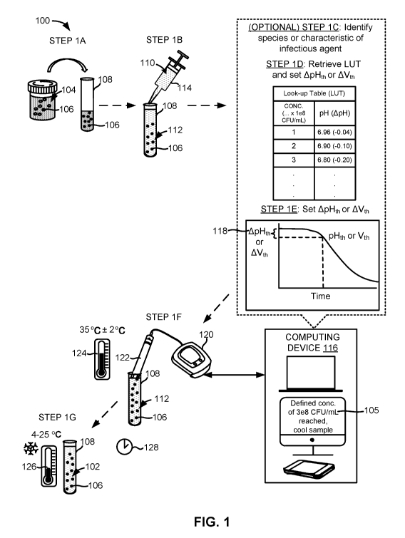
[0041] Fig. 1 illustrates one embodiment of a method 100 for preparing an
output
sample 102 from a source sample 104 comprising an infectious agent 106. More
specifically, the method 100 can provide an output sample 102 comprising a
defined
concentration 105 of the infectious agent 106.
[0042] The source sample 104 can comprise at least one of a biological
sample, a
bodily fluid, a wound swab or sample, a rectal swab or sample, and an
infectious agent
culture derived from the biological sample, the bodily fluid, the wound swab
or sample, or
the rectal swab or sample. The bodily fluid can comprise urine, blood, serum,
plasma,
saliva, sputum, semen, breast milk, joint fluid, spinal fluid such as
cerebrospinal fluid,
wound material, mucus, fluid accompanying stool, re-suspended rectal or wound
swabs,
vaginal secretions, synovial fluid, pleural fluid, peritoneal fluid,
pericardial fluid, amniotic
fluid, cultures of bodily fluid or samples that have tested positive for an
infectious agent or
infectious agent growth such as blood culture that has tested positive for an
infectious
agent or infectious agent growth (i.e., positive blood culture), or a
combination thereof.
8
CA 03085018 2020-06-01
WO 2019/113226 PCT/US2018/064093
[0043] The output sample 102 comprising the defined concentration 105 of
the
infectious agent 106 can be utilized as an inoculum for a downstream test such
as a
downstream anti-infective or antibiotic susceptibility test (AST) for
determining the
susceptibility of the infectious agent 106 to one or more anti-infectives or
antibiotics.
[0044] The infectious agents 106 that can be assayed using the methods or
systems
disclosed herein can be any metabolizing single- or multi-cellular organism
including
bacteria and fungi. In certain embodiments, the infectious agent 106 can be
bacteria
selected from the genera Acinetobacter, Acetobacter, Actinomyces, Aerococcus,
Aeromonas, Agrobacterium, Anaplasma, Azorhizobium, Azotobacter, Bacillus,
Bacteriodes, Bartonella, Bordetella, Borrelia, Brucella, Burkholderia,
Calymmatobacterium, Camp ylobacter, Chlamydia, Chlamydophila, Citrobacter,
Clostridium, Corynebacterium, Coxiella, Ehrlichia, Enterobacter, Enterococcus,
Escherichia, Francisella, Fusobacterium, Gardnerella, Haemophilus,
Helicobacter,
Klebsiella, Lactobacillus, Legionella, Listeria, Methanobacterium,
Microbacterium,
Micrococcus, Morganella, Moraxella, Mycobacterium, Mycoplasma, Neisseria,
Pandoraea, Pasteurella, Peptostreptococcus, Porphyromonas, Prevotella,
Proteus,
Providencia, Pseudomonas, Ralstonia, Raoultella, Rhizobium, Rickettsia,
Rochalimaea,
Rothia, Salmonella, Serratia, Shewanella, Shigella, Spirillum, Staphylococcus,
Strenotrophomonas, Streptococcus, Streptomyces, Treponema, Vibrio, Wolbachia,
Yersinia, or a combination thereof. In other embodiments, the infectious agent
106 can be
one or more fungi selected from the genera Candida or Cryptococcus or mold.
[0045] Other specific bacteria that can be quantified using the methods and
systems
disclosed herein can comprise Staphylococcus aureus, Staphylococcus
lugdunensis,
coagulase-negative Staphylococcus species (including but not limited to
Staphylococcus
epidermidis, Staphylococcus haemolyticus, Staphylococcus hominis,
Staphylococcus
capitis, not differentiated), Enterococcus faecalis, Enterococcus faecium
(including but not
limited to Enterococcus faecium and other Enterococcus spp., not
differentiated, excluding
Enterococcus faecalis), Streptococcus pneumoniae, Streptococcus pyo genes,
Streptococcus
agalactiae, Streptococcus spp., (including but not limited to Streptococcus
mitis,
Streptococcus pyo genes, Streptococcus gallolyticus, Streptococcus agalactiae,
Streptococcus pneumoniae, not differentiated), Pseudomonas aeruginosa,
Acinetobacter
baumannii, Klebsiella spp. (including but not limited to Klebsiella
pneumoniae, Klebsiella
oxytoca, not differentiated), Escherichia coli, Enterobacter spp. (including
but not limited
to Enterobacter cloacae, Enterobacter aero genes, not differentiated), Proteus
spp.
9
CA 03085018 2020-06-01
WO 2019/113226 PCT/US2018/064093
(including but not limited to Proteus mirabilis, Proteus vulgaris, not
differentiated),
Citrobacter spp. (including but not limited to Citrobacter freundii,
Citrobacter koseri, not
differentiated), Serratia marcescens, Candida albicans, Candida glabrata, and
Candida
tropicalis.
[0046] Other more specific bacteria that can be quantified can comprise
Acinetobacter
baumannii, Actinobacillus spp., Actinomycetes, Actinomyces spp. (including but
not limited
to Actinomyces israelii and Actinomyces naeslundii), Aeromonas spp. (including
but not
limited to Aeromonas hydrophila, Aeromonas veronii biovar sobria (Aeromonas
sobria),
and Aeromonas caviae), Anaplasma phagocytophilum, Alcaligenes xylosoxidans,
Actinobacillus actinomycetemcomitans, Bacillus spp. (including but not limited
to Bacillus
anthracis, Bacillus cereus, Bacillus subtilis, Bacillus thuringiensis, and
Bacillus
stearothermophilus), Bacteroides spp. (including but not limited to
Bacteroides fragilis),
Bartonella spp. (including but not limited to Bartonella bacilliformis and
Bartonella
henselae, Bifidobacterium spp., Bordetella spp. (including but not limited to
Bordetella
pertussis, Bordetella parapertussis, and Bordetella bronchiseptica), Borrelia
spp.
(including but not limited to Borrelia recurrentis, and Borrelia burgdorferi),
Brucella spp.
(including but not limited to Brucella abortus, Brucella canis, Brucella
melintensis and
Brucella suis), Burkholderia spp. (including but not limited to Burkholderia
pseudomallei
and Burkholderia cepacia), Campylobacter spp. (including but not limited to
Campylobacter jejuni, Campylobacter coli, Campylobacter lari and Campylobacter
fetus),
Capnocytophaga spp., Cardiobacterium hominis, Chlamydia trachomatis,
Chlamydophila
pneumoniae, Chlamydophila psittaci, Citrobacter spp., Coxiella burnetii,
Corynebacterium
spp. (including but not limited to, Corynebacterium diphtheriae,
Corynebacterium jeikeum
and Corynebacterium), Clostridium spp. (including but not limited to
Clostridium
perfringens, Clostridium difficile, Clostridium botulinum and Clostridium
tetani), Eikenella
corrodens, Enterobacter spp. (including but not limited to Enterobacter aero
genes,
Enterobacter agglomerans, Enterobacter cloacae and Escherichia coli, including
opportunistic Escherichia coli, including but not limited to enterotoxigenic
E. coli,
enteroinvasive E. coli, enteropathogenic E. coli, enterohemorrhagic E. coli,
enteroaggregative E. coli and uropathogenic E. coli), Enterococcus spp.
(including but not
limited to Enterococcus faecalis and Enterococcus faecium), Ehrlichia spp.
(including but
not limited to Ehrlichia chafeensia and Ehrlichia canis), Erysipelothrix
rhusiopathiae,
Eubacterium spp., Francisella tularensis, Fusobacterium nucleatum, Gardnerella
vaginalis, Gemella morbillorum, Haemophilus spp. (including but not limited to
CA 03085018 2020-06-01
WO 2019/113226 PCT/US2018/064093
Haemophilus influenzae, Haemophilus ducreyi, Haemophilus aegyptius,
Haemophilus
parainfluenzae, Haemophilus haemolyticus and Haemophilus parahaemolyticus,
Helicobacter spp. (including but not limited to Helicobacter pylon,
Helicobacter cinaedi
and Helicobacter fennelliae), Kin gella kingii, Klebsiella spp. (including but
not limited to
Klebsiella pneumoniae, Klebsiella granulomatis and Klebsiella oxytoca),
Lactobacillus
spp., Listeria monocytogenes, Leptospira interrogans, Legionella pneumophila,
Leptospira
interrogans, Peptostreptococcus spp., Moraxella catarrhalis, Morganella spp.,
Mobiluncus
spp., Micrococcus spp., Mycobacterium spp. (including but not limited to
Mycobacterium
leprae, Mycobacterium tuberculosis, Mycobacterium intracellulare,
Mycobacterium
avium, Mycobacterium bovis, and Mycobacterium marinum), Mycoplasm spp.
(including
but not limited to Mycoplasma pneumoniae, Mycoplasma hominis, and Mycoplasma
genitalium), Nocardia spp. (including but not limited to Nocardia asteroides,
Nocardia
cyriacigeorgica and Nocardia brasiliensis), Neisseria spp. (including but not
limited to
Neisseria gonorrhoeae and Neisseria meningitidis), Pasteurella multocida,
Plesiomonas
shigelloides, Prevotella spp., Porphyromonas spp., Prevotella melaninogenica,
Proteus
spp. (including but not limited to Proteus vulgaris and Proteus mirabilis),
Providencia spp.
(including but not limited to Providencia alcalifaciens, Providencia rettgeri
and
Providencia stuartii), Pseudomonas aeruginosa, Propionibacterium acnes,
Rhodococcus
equi, Rickettsia spp. (including but not limited to Rickettsia rickettsii,
Rickettsia akari and
Rickettsia prowazekii, Orientia tsutsugamushi (formerly: Rickettsia
tsutsugamushi) and
Rickettsia typhi), Rhodococcus spp., Stenotrophomonas maltophilia, Salmonella
spp.
(including but not limited to Salmonella enterica, Salmonella typhi,
Salmonella paratyphi,
Salmonella enteritidis, Salmonella cholerasuis and Salmonella typhimurium),
Serratia spp.
(including but not limited to Serratia marcesans and Serratia liquifaciens),
Shigella spp.
(including but not limited to Shigella dysenteriae, Shigella flexneri,
Shigella boydii and
Shigella sonnei), Staphylococcus spp. (including but not limited to
Staphylococcus aureus,
Staphylococcus epidermidis, Staphylococcus hemolyticus, Staphylococcus
saprophyticus),
Streptococcus spp. (including but not limited to Streptococcus pneumoniae (for
example
chloramphenicol-resistant serotype 4 Streptococcus pneumoniae, spectinomycin-
resistant
serotype 6B Streptococcus pneumoniae, streptomycin-resistant serotype 9V
Streptococcus
pneumoniae, erythromycin-resistant serotype 14 Streptococcus pneumoniae,
optochin-
resistant serotype 14 Streptococcus pneumoniae, rifampicin-resistant serotype
18C
Streptococcus pneumoniae, tetracycline-resistant serotype 19F Streptococcus
pneumoniae,
penicillin-resistant serotype 19F Streptococcus pneumoniae, and trimethoprim-
resistant
11
CA 03085018 2020-06-01
WO 2019/113226 PCT/US2018/064093
serotype 23F Streptococcus pneumoniae, chloramphenicol-resistant serotype 4
Streptococcus pneumoniae, spectinomycin-resistant serotype 6B Streptococcus
pneumoniae, streptomycin-resistant serotype 9V Streptococcus pneumoniae,
optochin-
resistant serotype 14 Streptococcus pneumoniae, rifampicin-resistant serotype
18C
Streptococcus pneumoniae, penicillin-resistant serotype 19F Streptococcus
pneumoniae, or
trimethoprim-resistant serotype 23F Streptococcus pneumoniae), Streptococcus
agalactiae,
Streptococcus mutans, Streptococcus pyo genes, Group A Streptococci,
Streptococcus
pyo genes, Group B Streptococci, Streptococcus agalactiae, Group C
Streptococci,
Streptococcus anginosus, Streptococcus equismilis, Group D Streptococci,
Streptococcus
bovis, Group F Streptococci, Streptococcus anginosus, and Group G
Streptococci),
Spirillum minus, Streptobacillus monihformi, Treponema spp. (including but not
limited to
Treponema carateum, Treponema petenue, Treponema pallidum and Treponema
endemicum, Tropheryma whippelii, Ureaplasma urealyticum, Veillonella spp.,
Vibrio spp.
(including but not limited to Vibrio cholerae, Vibrio parahemolyticus, Vibrio
vulnificus,
Vibrio parahaemolyticus, Vibrio vulnificus, Vibrio alginolyticus, Vibrio
mimicus, Vibrio
hollisae, Vibrio fluvialis, Vibrio metchnikovii, Vibrio damsela and Vibrio
fumisii), Yersinia
spp. (including but not limited to Yersinia enterocolitica, Yersinia pestis,
and Yersinia
pseudotuberculosis) and Xanthomonas maltophilia among others.
[0047] Furthermore, other infectious agents 106 that can be assayed using
the methods
and systems disclosed herein can comprise fungi or mold including, but not
limited to,
Candida spp. (including but not limited to Candida albicans, Candida glabrata,
Candida
tropicalis, Candida parapsilosis, and Candida krusei), Aspergillus spp.
(including but not
limited to Aspergillus fumigatous, Aspergillus flavus, Aspergillus clavatus),
Cryptococcous
spp. (including but not limited to Cryptococcus neoformans, Cryptococcus
gattii,
Cryptococcus laurentii, and Cryptococcus albidus), Fusarium spp. (including
but not
limited to Fusarium oxysporum, Fusarium solani, Fusarium verticillioides, and
Fusarium
prohferatum), Rhizopus oryzae, Penicillium marneffei, Coccidiodes immitis, and
Blastomyces dermatitidis.
[0048] The method 100 can comprise introducing aliquots of the source
sample 104
into reaction vessels 108 in step 1A. The reaction vessels 108 can refer to
one or more test
tubes, reaction tubes, wells of a high throughput assay plate or well plate
such as a 96-well
plate, a 192-well plate, or a 384-well plate, culture plates or dishes,
microfluidic conduits,
or other suitable containers for housing biological samples.
12
CA 03085018 2020-06-01
WO 2019/113226 PCT/US2018/064093
[0049] In additional embodiments not shown in Fig. 1, a stimulus solution
can be
added to the source sample 104 before metering out aliquots of the source
sample 104 to
the reaction vessels 108. The stimulus solution can be a nutrient or growth
solution. In
these and other embodiments, the source sample 104 can also be filtered before
step 1A.
This filtering step can involve filtering the source sample 104 using an
instance of a filter, a
microfluidic filter, or a combination thereof to filter out debris, inorganic
material, and
larger cellular components including blood cells or epithelial cells from the
source sample
104.
[0050] One or more fluid delivery conduits 110 can inject, deliver, or
otherwise
introduce aliquots of the source sample 104 to the reaction vessels 108. The
fluid delivery
conduits 110 can include tubes, pumps, containers, or microfluidic channels
for delivering
buffers, reagents, fluid samples including the source sample 104, or a
combination thereof
to and between devices, apparatus, or containers in the system. For example,
as shown in
Fig. 1, the fluid delivery conduits 110 can refer to parts of a pump such as a
syringe pump.
In other embodiments, the fluid delivery conduits 110 can include or refer to
at least part of
a hydraulic pump, a pneumatic pump, a peristaltic pump, a vacuum pump or a
positive
pressure pump, a manual or mechanical pump, or a combination thereof. In
additional
embodiments, the fluid delivery conduits 110 can include or refer to at least
part of an
injection cartridge, a pipette, a capillary, a dispenser bottle, or a
combination thereof. The
fluid delivery conduits 110 can also be part of a vacuum system configured to
draw fluid to
or through channels, tubes, or passageways under vacuum. Moreover, the fluid
delivery
conduits 110 can include or refer to at least part of a multichannel delivery
system or
pipette.
[0051] The method 100 can comprise diluting the aliquots of the source
sample 104 in
step 1B. For example, the aliquot of the source sample 104 can be diluted by a
dilution
factor or ratio to yield a diluted sample 112. The dilution factor can be
between about 1:1
to about 1:10. The dilution factor can also be between about 1:10 to about
1:100. In some
embodiments, the dilution factor can be between about 1:100 to about 1:103. In
other
embodiments, the dilution factor can also be between about 1:103 to about
1:107. In further
embodiments, the dilution factor can be greater than 1:107.
[0052] The aliquot of the source sample 104 can be diluted using a dilutive
solution
114. In some embodiments, the dilutive solution 114 can comprise growth media
or a
growth inducer. In these and other embodiments, the dilutive solution 114 can
be a solution
containing bacto-tryptone, tryptic soy digest, yeast extract, beef extract,
cation-adjusted
13
CA 03085018 2020-06-01
WO 2019/113226 PCT/US2018/064093
Mueller Hinton Broth (CAMHB), glucose supplemented Mueller Hinton broth (MHG),
starch, acid hydrolysate of casein, calcium chloride, magnesium chloride,
sodium chloride,
blood or lysed blood including lysed horse blood (LHB), CAMHB-LHB, glucose or
other
carbohydrates, or a combination thereof. The growth inducer can comprise a
carbon-based
inducer, a nitrogen-based inducer, a mineral, a trace element, a biological
growth factor, or
any combination thereof. For example, the growth inducer can include but is
not limited to
a carbohydrate such as glucose or starches, ammonia, magnesium, amino acids,
casamino
acids, vitamins, peptides, blood, or a combination thereof. In one example
embodiment, the
dilutive solution 114 can comprise tryptone, yeast extract, sodium chloride,
starch, water,
and glucose.
[0053] Although Fig. 1 illustrates one aliquot of the source sample 104
being diluted in
step 1B, it is contemplated by this disclosure that additional aliquots of the
source sample
104 can be diluted to the same dilution ratio or different dilution ratios to
yield additional
diluted samples (e.g., a second diluted sample, a third diluted sample, a
fourth diluted
sample, etc.). The additional diluted samples can be used to generate internal
controls or
redundant samples.
[0054] The method 100 can further comprise an optional step of identifying
a species
or other classification type or characteristic of the infectious agent 106 in
the source sample
104 in step 1C. In addition to species, the other classification type can
comprise a genus, a
family, an order, a class, a phylum, a kingdom, and a domain of the infectious
agent 106 in
the source sample 104.
[0055] In some embodiments, identifying the species or other classification
type of the
infectious agent 106 can involve receiving such information from a user via an
input device
(e.g., a keyboard or touchscreen) coupled to a computing device 116. In other
embodiments, identifying the species or other classification type of the
infectious agent
106 can involve receiving such information from another computing device
communicatively coupled to the computing device 116 or retrieving such
information from
a database. The classification-type (e.g., the species, the genus, the family,
etc.) or the
characteristic of the infectious agent 106 can be stored in a memory of the
computing
device 116, a computing cloud, or a remote server accessible to the computing
device 116
over a network.
[0056] In some embodiments, identifying the species of the infectious agent
106 in the
source sample 104 can involve determining the species 106 using a biochemical
test (e.g., a
test for metabolism or a test for specific enzymes), mass spectrometry,
genotyping,
14
CA 03085018 2020-06-01
WO 2019/113226 PCT/US2018/064093
phenotypic analysis from culture plates, test kits comprising phages, or a
combination
thereof. In some embodiments, the characteristic of the infectious agent 106
can be a
response of the infectious agent 106 to a Gram stain test. For example, step
1C can
comprise performing a Gram stain test and identifying the infectious agent 106
as Gram-
positive or Gram-negative bacteria.
[0057] In certain embodiments, the species of the infectious agent 106 in
the source
sample 104 can be identified but the particular strain of the infectious agent
106 can be left
unknown. In other embodiments, the classification-type or characteristic
(e.g., the species
or Gram-type) of the infectious agent 106 in the source sample 104 does not
need to be
identified prior to proceeding to other steps of the method 100.
[0058] The method 100 can further comprise selecting and retrieving a look-
up table
(LUT) from a database using the computing device 116 or another device in step
1D. The
LUT can be selected based on information concerning a classification-type or
characteristic
of the infectious agent 106 in the source sample 104 or a lack of such
information. For
example, a species-specific LUT 210 (see Fig. 2) for the bacterial species
Serratia
marcescens (SMa) can be selected and retrieved when the species of the
infectious agent
106 in the source sample 104 is identified as SMa. Also, as an example, a
universal LUT
212 (see Fig. 2) can be selected and retrieved when the species of the
infectious agent 106
in the source sample 104 has not been ascertained or is unknown. As additional
examples,
LUTs organized by genus, family, order, class, phylum, kingdom, or domain can
also be
selected and retrieved. Furthermore, LUTs organized by microbial
characteristics, such as
Gram-type, or functional capabilities, such as the ability to hydrolyze
certain proteins or
molecules, can also be selected or retrieved.
[0059] The LUTs can be stored as part of a database software program in a
memory of
the computing device 116. In other embodiments, the LUTs can be stored as part
of a
database software program in a computing cloud or a remote server accessible
to the
computing device 116 over a network. The computing device 116 or one or more
processors therein can search through hundreds or thousands of stored LUTs and
select an
appropriate LUT based on information concerning a classification-type (e.g., a
species) or
characteristic of the infectious agent 106 in the source sample 104.
[0060] As will be discussed in more detail in the following sections, the
species-
specific LUT 210, the universal LUT 212, and other LUTs organized by
classification or
characteristic can be generated from multiple strain-specific LUTs 204 (see
Fig. 2)
representing data measured from multiple reference samples 208 (see Fig. 2)
monitored
CA 03085018 2020-06-01
WO 2019/113226 PCT/US2018/064093
over time. When the LUT is a species-specific LUT 210, each of the multiple
reference
samples 208 can comprise a reference infectious agent 214 (see Fig. 2) of the
same species
as the infectious agent 106 in the source sample 104. When the LUT is a
universal LUT
212 or other type of inter-species LUT, at least one of the multiple reference
samples 208
can comprise a reference infectious agent 214 of a difference species from the
infectious
agent 106 in the source sample 104.
[0061] The method 100 can further comprise using the computing device 116
or
another device communicatively coupled to the computing device 116 to set a
threshold
amount 118 in step 1E. The threshold amount 118 can represent a target amount
by which a
solution characteristic of the diluted sample 112 is required to change in
order for the
concentration of the infectious agent 106 in the diluted sample 112 to reach
the defined
concentration 105. The threshold amount 118 can also represent a limit or
maximum
amount by which a solution characteristic of the diluted sample 112 is
permitted to change
(e.g., ApH of approximately -0.20) before the concentration of the infectious
agent 106 in
the diluted sample 112 exceeds the defined concentration 105. In some
embodiments, the
threshold amount 118 can be a threshold range (e.g., ApH of between
approximately -0.15
and -0.25).
[0062] The threshold amount 118 can be set using the computing device 116
(or
another device such as a parameter analyzer 120) communicatively coupled to
one or more
sensors 122 used to monitor the solution characteristic of the diluted sample
112. The
threshold amount 118 can be set based on the defined concentration 105,
concentration
data obtained from the retrieved LUT (e.g., the species-specific LUT 210 or
the universal
LUT 212), and solution characteristic data obtained from the retrieved LUT
(e.g., the
species-specific LUT 210 or the universal LUT 212). For example, the defined
concentration 105 of the output sample 102 can be set at 3 x 10⁸ colony-
forming units per
milliliter (CFU/mL) or 3e8 CFU/mL. Also, for example, the defined
concentration 105 of
the output sample 102 can be set at 5 x 10⁵ CFU/mL or 5e5 CFU/mL. Once the
computing
device 116 (or processors therein) has selected and retrieved an appropriate
LUT based on
a classification or characteristic of the infectious agent 106 in the source
sample 104, the
computing device 116 (or processors therein) can then set a threshold amount
118 of
ApH -0.20 based on concentration and solution characteristic data obtained
from the LUT.
[0063] The method 100 can further comprise exposing the sensor 122 to the
diluted
sample 112 or introducing the diluted sample 112 to the sensor 122 such that
at least part of
the sensor 122 is in fluid communication with the diluted sample 112 in step
1F. The part
16
CA 03085018 2020-06-01
WO 2019/113226 PCT/US2018/064093
of the sensor 122 in fluid communication with the diluted sample 112 can
comprise a
functionalization (or pH-active) layer (see Figs. 5A, 5B, 7A, and 7B) or a
redox-active
layer (see Figs. 6A, 6B, 7A, and 7B) of the sensor 122.
[0064] The sensor 122 can be configured to respond to a change in a
solution
characteristic of the diluted sample 112. In some embodiments, the sensor 122
can be a pH
sensor configured to respond to a change in the pH of the diluted sample 112.
In other
embodiments, the sensor 122 can be an oxidation reduction potential (ORP)
sensor
configured to respond to a change in the ORP of the diluted sample 112. In
additional
embodiments, the sensor 122 can be a combined pH and ORP sensor configured to
respond
to changes in the pH and ORP of the diluted sample 112.
[0065] Step 1F can also comprise incubating the diluted sample 112 at an
incubation
temperature 124 for a period of time. The diluted sample 112 can be incubated
while the
sensor 122 is exposed to the diluted sample 112. The diluted sample 112 can be
incubated
in the same reaction vessel 108 or transferred to a different reaction vessel
108 or
container.
[0066] The incubation temperature 124 can be between approximately 30 C
and 40 C.
In some embodiments, the incubation temperature 124 can be between
approximately 33
C and 37 C (or about 35 C 2 C). The diluted sample 112 can be incubated
at the
incubation temperature 124 for as long as needed for the concentration of the
infectious
agent 106 within the diluted sample 112 to reach the defined concentration
105. In some
embodiments, the incubation period can be between approximately 15 minutes and
60
minutes. In other embodiments, the incubation period can be between
approximately 60
minutes and 120 minutes. In additional embodiments, the incubation period can
be less
than 15 minutes or greater than 120 minutes.
[0067] In the example embodiment shown in Fig. 1, exposing the sensor 122
to the
diluted sample 112 can involve directly immersing at least part of a handheld
or probe
instance of the sensor 122 into the diluted sample. In this embodiment, the
handheld or
probe instance of the sensor 122 can be a handheld pH sensor or a handheld ORP
sensor
coupled to a standalone parameter analyzer 120, such as a voltmeter or
multimeter.
[0068] In another example embodiment contemplated by this disclosure,
introducing
the diluted sample 112 to the sensor 122 can involve injecting, delivering, or
otherwise
introducing the diluted sample to a well or container comprising the sensor
122 fabricated
on a substrate. In yet another example embodiment shown in Fig. 4A,
introducing the
diluted sample 112 to the sensor 122 can involve placing or positioning a
reaction vessel
17
CA 03085018 2020-06-01
WO 2019/113226
PCT/US2018/064093
404 (see Fig. 4A) comprising the diluted sample 112 into a sample preparation
apparatus
402 (see Fig. 4A) comprising built-in sensors 122 having contacts or
electrodes able to
access or be in fluid communication with the diluted sample 112. The sensor
122 will be
discussed in more detail in the following sections.
[0069] Step 1F can further comprise monitoring a change in the solution
characteristic
of the diluted sample 112 using a parameter analyzer 120 coupled to the sensor
122 or a
computing device 116 coupled to the parameter analyzer 120 or the sensor 122.
The
solution characteristic of the diluted sample 112 can be monitored in the
absence of any
exogenous reporter molecules added to the diluted sample 112.
[0070] Although Fig. 1 shows the parameter analyzer 120 as a separate
standalone
device from the computing device 116, it is contemplated by this disclosure
and it should
be understood by one of ordinary skill in the art that the parameter analyzer
120 and the
computing device 116 can be integrated into one device. As illustrated in Fig.
1, the
computing device 116 can be a mobile device, a handheld device, a tablet
device, a laptop
or desktop computer. In some embodiments, the parameter analyzer 120 can
wirelessly
communicate a signal or result to computing device 116.
[0071] The solution characteristic of the diluted sample 112 can change as
the amount
of ions or the amount of electro-active redox species in solution change due
to the energy
use, oxygen uptake or release, growth, or metabolism of the infectious agent
106 in the
diluted sample 112. For example, the amount of electro-active redox species in
the diluted
sample 112 can change as a result of cellular activity (e.g., microbial
aerobic or anaerobic
respiration) undertaken by the infectious agents 106 in the diluted sample
112. Also, as an
example, the amount of fl+ ions in the diluted sample 112 can change as a
result of cellular
activity undertaken by the infectious agents 106 in the diluted sample 112.
[0072] As a more specific example, the amount of electron donors from Table
1 below
(e.g., the amount of energy carriers such as nicotinamide adenine dinucleotide
(NADH)
and flavin adenine dinucleotide (FADH2)) in the diluted sample 112 can change
due to the
growth of the infectious agent 106 in the diluted sample 112. Also, as another
more
specific example, the amount of oxygen depleted in the diluted sample 112 due
to aerobic
respiration can change due to the growth of the infectious agent 106 in the
diluted sample
112.
TABLE 1: Below is a "redox tower" visualizing potential electron donors and
acceptors
which can be utilized by infectious agents during the course of metabolism. An
electron
18
CA 03085018 2020-06-01
WO 2019/113226 PCT/US2018/064093
donor will have a greater negative potential than the electron acceptor. In
aerobic
respiration for example, 02 can serve as a terminal electron acceptor whereas
in anaerobic
respiration, the terminal electron acceptor can comprise NO3-, Fe3+, Mn4+,
S042-, or CO2.
Electron Donor and Acceptor Measured Standard Standard Reduction
Pairs Reduction Potential E'o Potential E'o (mV)
(mV) range
Glucose # 2 Pyruvate + 2e- -720 -700
-600
Glucose # 6 CO2+ 24e- -500 -500
H2 2H+ + 2e- -420 -400
NADH NAD+ + 2e- -320 -300
2 GSH tE; GSSG + 2e- -240 -200
H2S S042- + 8e- -220
FADH2f4 FAD + 2H+ + 2e- -220
Lactate "5---; P ruvate + 2e- -190 -100
Succinate Fumarate + 2e- 33 0
Cyt b (red) Cyt b (ox) + e- 80
Ubiquinol Ubiquinone + 2e- 110 100
Cyt c (red) t# Cyt c (ox) + e- 250 200
Cyt a (red) Cyt a (ox) + e- 290
300
NO2- + H20 =1*.=.,' NO3- + 2e- 420 400
NH4 + + H20 NO2- + 6e- 440
Mn2+ + H20 Mn02 + 2e- 460
500
600
1/2 N2 3H20 1;-NO3- 5e- 740 700
Fe2+ Fe3+ + le- 770
H20 f-1:-; 1/2 02+ 2H+ + 2e- 820 800
700
[0073] When the solution characteristic monitored is pH, the threshold
amount 118 can
be between approximately ApH 0.01 and ApH 3Ø As a more specific example, the
threshold amount 118 can be set at approximately ApH 0.20 (i.e., a pH
threshold level
(pHth) of pH 6.8 can be set when a starting pH is normalized to pH 7.0). When
the solution
characteristic monitored is ORP, the threshold amount 118 can be between
approximately
A100mV and A700mV. As a more specific example, the threshold amount 118 can be
set at
approximately A100mV (i.e., an ORP threshold level (Vth) of -100mV can be set
when a
starting ORP is normalized to 0 mV).
[0074] The method 100 can further comprise cooling the diluted sample 112
to a
cooling temperature 126 when the solution characteristic of the diluted sample
112 changes
19
CA 03085018 2020-06-01
WO 2019/113226 PCT/US2018/064093
by the threshold amount 118 in step 1G. The diluted sample 112 can be cooled
when the
concentration of the infectious agent 106 within the diluted sample 112
reaches the defined
concentration 105 (i.e., when the threshold amount 118 is reached). Once the
concentration
of the infectious agent 106 within the diluted sample 112 reaches the defined
concentration
105, the diluted sample 112 can be considered or referred to as the output
sample 102.
[0075] The cooling temperature 126 can be between approximately 4 C and 25
C. In
some embodiments, the cooling temperature 126 can be between approximately 4 C
and
15 C. In other embodiments, the cooling temperature 126 can be below 4 C and
above 25
C.
[0076] In one embodiment, the computing device 116 or the parameter
analyzer 120
can alert a user that the solution characteristic of the diluted sample 112
has changed by the
threshold amount 118. For example, the computing device 116 or the parameter
analyzer
120 can generate an audible alert, a visual or graphic alert, a haptic or
motion alert, or a
combination thereof when the solution characteristic of the diluted sample 112
has changed
by the threshold amount 118. As a more specific example, the computig device
116 or the
parameter analyzer 120 can generate a message informing a user that the the
solution
characteristic of the diluted sample 112 has changed by the threshold amount
118.
[0077] The diluted sample 112 can be cooled to the cooling temperature 126
by being
placed in an ice bath. The diluted sample 112 can also be cooled to the
cooling temperature
126 by being placed in a refrigerator or freezer, a cold compartment, a
cooling device, or a
combination thereof. When the method 100 is implemented using an integratd
system such
as the system 400 shown in Fig. 4A, the diluted sample 112 can be cooled by a
cooling
component integrated within the sample preparation appratus 402 (see Fig. 4A).
[0078] The method 100 can further comprise diluting the output sample 102
by another
dilution factor to yield a futher diluted sample. The further diluted sample
can comprise an
infectious agent concentration required for a downstream test such as a
downstream AST
assay. In this case, the futher diluted sample can serve as the input sample
for the
downstream test. The diluent in the further diluted sample can be of any
temperature and,
thus, act as a coolant to cool the further diluted sample.
[0079] Using the method 100 and systems described herein, a laboratory or
hospital
can prepare an output sample 102 of a defined concentration 105 from a source
sample 104
within a shortened preparation period 128. Using the method 100 and systems
described
herein, the preparation period 128 can be between approximately 60 minutes and
120
minutes. In other embodiments, the preparation period 128 can be between
approximately
CA 03085018 2020-06-01
WO 2019/113226 PCT/US2018/064093
1 minute and 60 minutes. In additional embodiments, the preparation period 128
can be
between approximately 120 minutes and 240 minutes. In some embodiments, the
preparation period 128 can be greater than 240 minutes.
[0080] One or more of the aforementioned steps of the method 100 can be
stored as
machine-executable instructions or logical commands in a non-transitory
machine-readable
medium (e.g., a memory or storage unit) of the computing device 116 or another
device
communicatively or electrically coupled to the computing device 116. Any of
the
parameter analyzer 120, the computing device 116, or another device coupled to
the
parameter analyzer 120 or the computing device 116 can comprise one or more
processors
or controllers configured to execute the aforementioned instructions or
logical commands.
[0081] The steps depicted in Fig. 1 do not require the particular order
shown to achieve
the desired result. Moreover, certain steps or processes may be omitted or
occur in parallel
in order to achieve the desired result. In addition, any of the systems or
devices disclosed
herein can be used in lieu of devices or systems shown in the steps of Fig. 1.
[0082] Fig. 2 illustrates an example method 200 for generating a composite
or averaged
look-up table (LUT) 202 from multiple strain-specific LUTs 204. The multiple
strain-
specific LUTs 204 can represent experimental data 206 obtained from monitoring
multiple
reference samples 208 over time. The averaged LUT 202 can be any of the
species-
specific LUT 210, the universal LUT 212, or another LUT organized by
classification-type
or characteristic. For example, the averaged LUT 202 can also be a Gram-
positive LUT or
a Gram-negative LUT. Each of the reference samples 208 can comprise a
reference
infectious agent 214 of a known strain and a known species.
[0083] The species-specific LUT 210 can be generated from multiple strain-
specific
LUTs 204 representing experimental data 206 obtained from monitoring multiple
reference
samples 208 where each of the references samples 208 comprises a reference
infectious
agent 214 of the same species as the infectious agent 106 in the source sample
104. For
example, a species-specific LUT 210 can be generated for SMa from multiple
strain-
specific LUTs 204 including LUTs representing the CDC-27 strain of SMa (SMa
CDC-
27), the CDC-91 strain of SMa (SMa CDC-91), the CDC-99 strain of SMa (SMa CDC-
99), the CDC-121 strain of SMa (SMa CDC-121), the CDC-122 strain of SMa
(SMa CDC-122), the CDC-130 strain of SMa (SMa CDC-130), or a combination
thereof.
As another example, a species-specific LUT 210 can also be generated for
Staphylococcus
aureus (SAu) from multiple strain-specific LUTs 204 including LUTs comprising
the
wildtype strain of SAu (SAu WT), the CDC-483 strain of SAu (SAu CDC-483), the
21
CA 03085018 2020-06-01
WO 2019/113226 PCT/US2018/064093
CDC-475 strain of SAu (SAu CDC-475), the ATCC43300 strain of SAu (SAu-ATCC-
43300), or a combination thereof.
[0084] The universal LUT 212 can be generated from multiple strain-specific
LUTs
204 representing experimental data 206 obtained from monitoring multiple
reference
samples 208 comprising references infectious agents 214 of different species.
For example,
a universal LUT 212 can be generated from multiple strain-specific LUTs 204
across
several species including strain-specific LUTs 204 representing the species
SMa, SAu,
Escherichia coli (ECo), Enterobacter cloacae (Ed), Enterobacter aero genes
(EAe),
Klebsiella pneumoniae (KPn), or any combination thereof.
[0085] The reference samples 208 can be prepared by re-suspending
infectious agent
colonies from an infectious agent culture plate into growth media to reach an
initial
concentration. As a more specific example, the reference samples can be liquid
bacterial
cultures prepared by inoculating bacterial colonies from a bacterial culture
plate into
growth media. For example, the initial concentration of reference infectious
agents 214 can
be approximately 1 x 10⁷ (or 1e7) CFU/mL.
[0086] The method 200 can comprise monitoring changes in the solution
characteristic
of the reference samples 208 over a period of time in step 2A. The solution
characteristics
can be monitored by introducing the reference samples 208 to the sensors 122
or otherwise
exposing the sensors 122 to the reference samples 208 such that a
functionalization layer
(see Figs. 5A, 5B, 7A, and 7B) or a redox-active layer (see Figs. 6A, 6B, 7A,
and 7B) of
the sensors 122 is in fluid communication with the reference samples 208. When
the
sensors 122 are pH sensors, the solution characteristic monitored can be
solution pH. When
the sensors 122 are ORP sensors, the solution characteristic monitored can be
solution
ORP. The solution characteristics of the reference samples 208 can be
monitored in the
absence of any exogenous reporter molecules added to the reference samples
208. The
reference samples 208 can also be incubated at an incubation temperature 124
while the
solution characteristics of the reference samples 208 are monitored by the
sensors 122.
[0087] In some embodiments, the sensors 122 can be coupled to parameter
analyzers
120 communicatively coupled to the computing device 116 or the sensors 122 can
be
coupled directly to the computing device 116. The computing device 116 can
record and
store data concerning a change in the solution characteristic of a reference
sample 208 at
specific time intervals 216. For example, the computing device 116 can store a
change in
the pH of a reference sample 208 every 5 minutes, every 10 minutes, or every
15 minutes.
In some embodiments, the time intervals 216 can be between approximately 30
seconds
22
CA 03085018 2020-06-01
WO 2019/113226
PCT/US2018/064093
and 20 minutes. In other embodiments, the time intervals 216 can be between
approximately 1 second and 30 seconds or greater than 20 minutes.
[0088] The method 200 can further comprise conducting sample enumeration
assays
218 of the references samples 208 over the same period of time. A sample
enumeration
assay 218 can be a test or measurement conducted in order to determine a
concentration of
a reference infectious agent 214 in a reference sample 208 at a particular
point in time. The
concentration of the reference infectious agent 214 in the reference sample
208 can
increase over a period of time as the references samples 208 are incubated and
the growth
media provides nutrients for the reference infectious agent 214.
[0089] In some embodiments, the sample enumeration assay 218 can comprise
an
optical density (0.D.) measurement, a plate count assay, or a flow cytometry
assay. In
other embodiments, the sample enumeration assay 218 can be other tests or
measurements
for determining a concentration of a reference infectious agent 214 in a
reference sample
208. For example, the sample enumeration assay 218 can be an O.D. measurement
conducted at a wavelength of 600 nm (0D600 measurements) using a
spectrophotometry
device or system. The sample enumeration assay 218 can be conducted by devices
or
systems (e.g., a detector) communicatively coupled to the computing device
116, either
directly or indirectly. The computing device 116 can record and store the
results of such
sample enumeration assays 218 in one or more databases stored in a memory of
the
computing device 116, a computing cloud, or a remote sever accessible to the
computing
device 116.
[0090] The sample enumeration assays 218 can be conducted concurrently with
the
monitoring and recording of the changes in the solution characteristic of the
reference
samples 208. For example, O.D. measurements can be taken at the same time
intervals 216
as measurements of the changes in the solution characteristics of the
reference samples
208. As a more specific example, a sample enumeration assay 218 (e.g., an O.D.
measurement) can be conducted on the reference sample 208 and a solution
characteristic
change of the same reference sample 208 can be recorded every 5 minutes. In
other
embodiments, the sample enumeration assays 218 can be conducted immediately
before or
immediately after changes in the solution characteristic of the reference
samples 208 are
recorded.
[0091] The method 200 can also comprise converting the results of the
sample
enumeration assays 218 to reference sample concentrations 220 using a
conversion factor.
For example, the results of O.D. measurements can be converted to reference
sample
23
CA 03085018 2020-06-01
WO 2019/113226
PCT/US2018/064093
concentrations 220 (expressed as CFU/mL) by multiplying the results of the
O.D.
measurements by a numerical conversion factor (e.g., O.D. x (1.76 x 10⁹)). The
conversion
factors are usually instrument dependent and vary from instrument to
instrument. The
computing device 116 (or processors therein) or another device communicatively
coupled
to the computing device 116 can be programmed to convert the results of the
sample
enumeration assays 218 to reference sample concentrations 220 and store such
reference
sample concentrations 220 in one or more databases stored in a memory of the
computing
device 116, a computing cloud, or a remote server accessible to the computing
device 116.
[0092] The method 200 can further comprise generating each of the multiple
strain-
specific LUTs 204 by associating the calculated reference sample
concentrations 220 with
changes in the solution characteristic of a particular reference sample 208 at
specific time
intervals 216 in step 2B. For example, the strain-specific LUT 204 for SMa CDC-
27 can
be generated by associating the calculated reference sample concentrations 220
for this
particular reference sample 208 with the changes in the solution
characteristic of the
reference sample 208 measured every 5 minutes or every 10 minutes.
[0093] The method 200 can further comprise generating an averaged LUT 202
using
data obtained from multiple strain-specific LUTs 204 in step 2C. As previously
discussed,
the averaged LUT 202 can refer to any of the species-specific LUT 210, the
universal LUT
212, or another LUT organized by classification-type or characteristic. For
example, the
averaged LUT 202 can also be a Gram-positive LUT or a Gram-negative LUT. When
the
averaged LUT 202 is a species-specific LUT 210, the strain-specific LUTs 204
used to
generate the species-specific LUT 210 can encompass different strains of the
same species
of the infectious agent. When the averaged LUT 202 is a universal LUT 212, the
strain-
specific LUTs 204 used to generate the universal LUT 212 can encompass
different strains
of infectious agents across different species.
[0094] In one embodiment, the averaged LUT 202 can be generated by taking
an
average of all solution characteristic change amounts 222 across multiple
strain-specific
LUTs 204 to yield a number of averaged solution characteristic change amounts
224.The
averaged solution characteristic change amounts 224 can be calculated for each
predetermined reference sample concentration 220. For example, the
predetermined
reference sample concentrations 220 can comprise 1 x 10⁸ CFU/mL, 2 x 10⁸
CFU/mL, 3 x
108 CFU/mL, etc. In this example, the averaged LUT 202 can be generated by
calculating
each averaged solution characteristic change amount 224 from solution
characteristic
change amounts 222 obtained from multiple strain-specific LUTs 204.
24
CA 03085018 2020-06-01
WO 2019/113226 PCT/US2018/064093
[0095] Step 2C can further comprise associating each of the predetermined
reference
sample concentrations 220 with the results of the averaging calculations. For
example, the
averaged LUT 202 can be generated by associating the predetermined reference
sample
concentrations 220 with the averaged solution characteristic change amounts
224.
[0096] The averaged LUT 202 can be selected and retrieved based on
information
concerning a classification-type or characteristic of the infectious agent 106
in the source
sample 104 (see Fig. 1) or a lack of such information. For example, a species-
specific LUT
210 for SMa can be selected and retrieved when the species of the infectious
agent 106 in
the source sample 104 is identified as SMa. Also, as an example, a universal
LUT 212 can
be selected and retrieved when the species of the infectious agent 106 in the
source sample
104 has not been ascertained or is unknown. As additional examples, averaged
LUTs 202
organized by genus, family, order, class, phylum, kingdom, or domain can also
be selected
and retrieved. Furthermore, averaged LUTs 202 organized by microbial
characteristics,
such as Gram-type, or functional capabilities, such as the ability to
hydrolyze certain
proteins or molecules, can also be selected or retrieved.
[0097] As previously discussed, the LUTs can be stored as part of a
database software
program in a memory of the computing device 116. In other embodiments, the
LUTs can
be stored as part of a database software program in a computing cloud or a
remote server
accessible to the computing device 116 over a network. The computing device
116 or one
or more processors therein can search through hundreds or thousands of stored
LUTs and
select an appropriate LUT based on information concerning a classification-
type (e.g., a
species) or characteristic of the infectious agent 106 in the source sample
104.
[0098] Although method 200 is shown separate from method 100, it is
contemplated by
this disclosure and it should be understood by one of ordinary skill in the
art that method
200 can be considered sub-steps or pre-steps of method 100. Moreover, the
steps depicted
in Fig. 2 do not require the particular order shown to achieve the desired
result. Moreover,
certain steps or processes may be omitted or occur in parallel in order to
achieve the
desired result. In addition, any of the systems or devices disclosed herein
can be used in
lieu of devices or systems shown in the steps of Fig. 2.
[0099] Fig. 3A illustrates example strain-specific LUTs 204 for various
strains of SMa
used to generate a species-specific LUT 210 for SMa. As shown in Fig. 3A, the
strain-
specific LUTs 204 can comprise a SMa CDC-27 LUT, a SMa CDC-91 LUT, a
SMa CDC-99 LUT, SMa CDC-121 LUT, SMa CDC-122 LUT, and a SMa CDC-130
LUT. Although six strain-specific LUTs 204 are shown in the example embodiment
of Fig.
CA 03085018 2020-06-01
WO 2019/113226 PCT/US2018/064093
3A, it is contemplated by this disclosure that an averaged LUT 202, such as a
species-
specific LUT 210 or a universal LUT 212, can be generated from at least three
strain-
specific LUTs 204. Increasing the number of strain-specific LUTs 204 can
increase the
accuracy of the averaged LUTs 202.
[0100] The strain-specific LUTs 204 can comprise reference sample
concentrations
220 and solution characteristic change amounts 222. The solution
characteristic change
amounts 222 can be obtained from monitoring the change in the solution
characteristic of a
reference sample 208 comprising a strain of SMa over a period of time. For
example, Fig.
3B illustrates a pH growth curve 300 representing the change in pH of a
reference sample
208 comprising SMa CDC-27.
[0101] The reference sample concentrations 220 can be obtained by
converting results
of sample enumeration assays 218 (see Fig. 2) performed on the reference
sample 208
concurrently with monitoring the change in solution characteristic of the
reference sample
208. For example, Fig. 3B illustrates a reference sample concentration curve
302
representing an increase in the infectious agent concentration within the
reference sample
208 as measured by sample enumeration assays 218 performed on the reference
sample
208 over time. As shown in Fig. 3B, the pH growth curve 300 and the reference
sample
concentration curve 302 can be plotted using the same x-axis (time in
minutes).
[0102] Fig. 3A also illustrates that the species-specific LUT 210 for SMa
can be
generated by taking an average of the solution characteristic change amounts
222 across
the various strain-specific LUTs 204 for SMa. For example, at a reference
sample
concentration 220 of 1e8 CFU/mL, the averaged solution characteristic change
amount 224
can be calculated as 6.96 or a ApH of -0.04.
[0103] Fig. 4A illustrates an example of a system 400 for preparing an
output sample
102 from a source sample 104 comprising an infectious agent 106. More
specifically, the
system 400 can provide an output sample 102 comprising a defined concentration
105 of
the infectious agent 106.
[0104] The system 400 can comprise a sample preparation apparatus 402 that
integrates
the functionality of the computing device 116, the parameter analyzer 120, and
the sensor
122. The system 400 can undertake any of the steps of method 100 of Fig. 1.
For example,
one or more processors within the sample preparation apparatus 402 can
undertake any of
the steps 1C, 1D, or lE of method 100
[0105] In addition, the system 400 can comprise one or more reaction
vessels 404
compatible with the sample preparation apparatus 402. For example, the source
sample 104
26
CA 03085018 2020-06-01
WO 2019/113226 PCT/US2018/064093
can be introduced into a reaction vessel 404 and the reaction vessel 404 can
be placed or
positioned within a vessel receiving space 406 of the sample preparation
apparatus 402.
[0106] In another embodiment shown in Fig. 4B, a test cartridge 408 can be
used
instead of or in addition to the reaction vessel 404. The test cartridge 408
can comprise a
sample receiving surface 410 or space and a sample output surface 412 or
space. The
sample receiving surface 410 or space of the test cartridge 408 can receive an
aliquot of the
source sample 104 and the output sample 102 can be injected, pumped, or
otherwise
introduced into the sample output surface 412 or space. The test cartridge 408
can interface
with the sample preparation apparatus 402 via a cartridge interface 414. The
cartridge
interface 414 can be an electronic interface, such as a Universal Serial Bus
(USB) interface,
a high-speed serial computer expansion bus interface, or a combination
thereof, configured
to allow the sample preparation apparatus 402 to read or retrieve information
from the test
cartridge 408. In embodiments where the test cartridge 408 is used instead of
a reaction
vessel 404, the vessel receiving space 406 can be configured as a cartridge
receiving slot or
space.
[0107] In one embodiment, a user can begin the process of obtaining an
output sample
102 from a source sample 104 by placing the reaction vessel 404 (or the test
cartridge 408)
comprising the source sample 104 into the vessel receiving space 406 (or the
cartridge
receiving slot) of the sample preparation apparatus 402 and inputting a
defined
concentration 105 in the sample preparation apparatus 402. For example, the
defined
concentration 105 can be a concentration of 3e8 or 5e5 CFU/mL. The defined
concentration 105 can be inputted through an input component of the sample
preparation
apparatus 402 such as a keyboard, a touchscreen, or a combination thereof. In
other
embodiments, the defined concentration 105 can be inputted through a computing
device
(such as a mobile device or a laptop) communicatively coupled to the sample
preparation
apparatus 402 and the defined concentration 105 can be transmitted to the
sample
preparation apparatus 402.
[0108] In another embodiment, a user can begin the process of obtaining the
output
sample 102 from the source sample 104 by inputting or otherwise providing
information
concerning the classification (e.g., species, family, order, etc.) or
characteristic (Gram-
positive or Gram-negative) of the infectious agent 106 within the source
sample 106 and
the system 400 can determine the defined concentration 105 of the output
sample 102
needed for any downstream testing.
27
CA 03085018 2020-06-01
WO 2019/113226 PCT/US2018/064093
[0109] In some embodiments, one or more metering conduits within the sample
preparation apparatus 402 can then dilute the source sample 104 by introducing
a dilutive
solution 114 to the source sample 104 to yield the diluted sample 112. The
metering
conduits can refer to channels, passageways, capillaries, tubes, or a
combination thereof
within the sample preparation apparatus 402. The metering conduits can also
refer to
channels (e.g., microfluidic channels), passageways, capillaries, or tubes
serving as part of
hydraulic pump, a pneumatic pump, peristaltic pump, a vacuum or positive
pressure pump,
a manual or mechanical pump, a syringe pump, or a combination thereof within
the sample
preparation apparatus 402.
[0110] In one embodiment, the source sample 104 can be drawn or pumped
(e.g.,
through vacuum pressure) from the reaction vessel 404 into channels,
passageways,
capillaries, tubes, or a combination thereof within the sample preparation
apparatus 402. In
this embodiment, the dilutive solution 114 can be introduced to the source
sample 104 once
the source sample 104 has been drawn or pumped from the reaction vessel 404.
In other
embodiments, the test cartridge 408 can comprise channels, conduits, or
capillaries for
pumping or delivering the diluted sample 112, the dilutive solution 114, the
source sample
104, the output sample 102, or a combination thereof.
[0111] In other embodiments, the source sample 104 can remain within the
reaction
vessel 404 (or the test cartridge 408) and the dilutive solution 114 can be
introduced into
the reaction vessel 404 (or the test cartridge 408) through one or more ports
along a base,
top, or side of the reaction vessel 404. In other embodiments, the dilutive
solution 114 can
be introduced into the reaction vessel 404 (or the test cartridge 408) through
one or more
ports defined on a cap or cover of the reaction vessel 404.
[0112] In other embodiments, the source sample 104 can be diluted by the
dilutive
solution 114 prior to placement into the sample preparation apparatus 402.
[0113] In some embodiments, at least a portion of the sensor 122 can extend
into or be
in fluid communication with the diluted sample 112 within the reaction vessel
402 (or
within or on the test cartridge 408). For example, the electrodes (e.g., the
active electrode
and the reference electrode) can extend into or be in fluid communication with
the diluted
sample 112 through ports along the base of the reaction vessel 404 (or the
test cartridge
408). In other embodiments where the source sample 104 or the diluted sample
112 is
drawn or directed into the sample preparation apparatus 402, the diluted
sample 112 can be
introduced to the sensor 122 within the sample preparation apparatus 402 via
one or more
28
CA 03085018 2020-06-01
WO 2019/113226 PCT/US2018/064093
fluid delivery conduits such as channels (e.g., microfluidic channels),
passageways,
capillaries, or tubes within the sample preparation apparatus 402.
[0114] In some embodiments, the sensor 122 of the sample preparation
apparatus 402
can be a pH sensor comprising a reference electrode and an active electrode.
In these
embodiments, the active electrode can comprise a functionalization (or pH-
active) layer
508 (see Figs. 5A and 5B).
[0115] In other embodiments, the sensor 122 of the sample preparation
apparatus 402
can be an ORP sensor comprising a reference electrode and an active electrode.
In these
embodiments, the active electrode can comprise a redox-active layer 610 (see
Figs. 6A and
6B). As will be discussed in more detail, the redox-active layer 610 can
comprise a metal
layer or metal electrode.
[0116] In yet additional embodiments, the sensor 122 of the sample
preparation
apparatus 402 can be a combined pH and ORP sensor comprising multiple
reference
electrodes and active electrodes. In these embodiments, at least one active
electrode can
comprise the redox-active layer 712 and at least another active electrode can
comprise the
functionalization layer 716 (see Figs. 7A and 7B).
[0117] In some embodiments not shown in the figures, the sensor 122 (or
parts therein)
can be integrated within the test cartridge 408. For example, the diluted
sample 112 or the
source sample 104 can be in fluid communication with the functionalization (or
pH-active)
layer or the redox-active layer and a reference electrode of the sensor 122 by
virtue of the
diluted sample 112 or the source sample 104 being introduced on the sample
receiving
surface 410. In other examples, at least part of the test cartridge 408 can be
immersed
within the diluted sample 112.
[0118] One or more processors within the sample preparation apparatus 402
can be
programmed to retrieve an averaged LUT 202 such as a species-specific LUT 210
based on
information concerning a species of the infectious agent 106 in the source
sample 104. In
other embodiments, the one or more processors within the sample preparation
apparatus
402 can be programmed to retrieve a universal LUT 212 or another type of inter-
species
LUT based on a lack of information concerning the infectious agent 106 in the
source
sample 104.
[0119] The LUTs can be stored as part of a database software program in a
memory of
the sample preparation apparatus 402. In other embodiments, the LUTs can be
stored as
part of a database software program in a computing cloud or a remote server
accessible to
the sample preparation apparatus 402 over a network. One or more processors of
the
29
CA 03085018 2020-06-01
WO 2019/113226 PCT/US2018/064093
sample preparation apparatus 402 can be programmed to search through hundreds
or
thousands of stored LUTs to select an appropriate LUT based on a
classification-type (e.g.,
a species) or characteristic of the infectious agent 106 in the source sample
104.
[0120] The one or more processors of the sample preparation apparatus 402
can be
programmed to set a threshold amount 118 based on the defined concentration
105 and
data from the averaged LUT 202. For example, the defined concentration 105 can
be
inputted by the user into the sample preparation apparatus 402 as 3e8 or 5e5
CFU/mL. The
one or more processors of the sample preparation apparatus 402 can be
programmed to
select the averaged solution characteristic change amount 224 of ApH -0.20 as
the
threshold amount 118 since such a solution characteristic change amount is
associated with
a reference sample concentration 220 of 3e8 or 5e5 CFU/mL.
[0121] The sample preparation apparatus 402 can also comprise an incubating
component to incubate the diluted sample 112 to the incubation temperature 124
of
between approximately 30 C and 40 C (or about 35 C 2 C). For example, the
incubating component can incubate the diluted sample 112 within the reaction
vessel 404
or incubate the diluted sample 112 drawn or pumped into the sample preparation
apparatus
402. In other embodiments, the incubating component can incubate the entire
test cartridge
408 or a portion therein comprising the diluted sample 112.
[0122] The sample preparation apparatus 402 can monitor a change in the
solution
characteristic (e.g., a pH or ORP) of the diluted sample 112 while the diluted
sample 112 is
being incubated. The sensor 122 of the sample preparation apparatus 402 can be
configured
to respond to a change in the solution characteristic (e.g., the pH or ORP) of
the diluted
sample 112. The solution characteristic of the diluted sample 112 can be
monitored in the
absence of any exogenous reporter molecules added to the diluted sample 112.
[0123] The sample preparation apparatus 402 can comprise a cooling
component to
cool the diluted sample 112. The cooling component can cool the diluted sample
112 to a
cooling temperature 126 when the solution characteristic of the diluted sample
112 changes
by the threshold amount 118. The diluted sample 112 can be cooled when the
concentration
of the infectious agent 106 within the diluted sample 112 reaches the defined
concentration
105.
[0124] The cooling temperature 126 can be between approximately 4 C and 25
C. In
some embodiments, the cooling temperature 126 can be between approximately 4 C
and
15 C.
CA 03085018 2020-06-01
WO 2019/113226
PCT/US2018/064093
[0125] In some embodiments, the sample preparation apparatus 402 can cool
the same
reaction vessel 404 comprising the diluted sample 112. In these embodiments,
the now
cooled diluted sample 112 within the same reaction vessel 404 can be
considered the
output sample 102 when the concentration of the infectious agent 106 within
the reaction
vessel 404 reaches the defined concentration 105.
[0126] In other embodiments, the cooling component can cool the entire test
cartridge
408 or a portion therein comprising the diluted sample 112. In these
embodiments, the now
cooled diluted sample 112 within the test cartridge 408 can be considered the
output
sample 102 when the concentration of the infectious agent 106 within the test
cartridge 408
reaches the defined concentration 105.
[0127] In other embodiments, the diluted sample 112 can be introduced,
pumped, or
otherwise transferred to a different reaction vessel 404 (or a different part
of the test
cartridge 408) to be cooled. In these embodiments, the cooled diluted sample
112 within
the different reaction vessel 404 (or the different part of the test cartridge
408, such as the
sample output surface 412 or space) can be considered the output sample 102.
[0128] In one embodiment, sample preparation apparatus 402 can alert a user
that the
solution characteristic of the diluted sample 112 has changed by the threshold
amount 118
and that the infectious agent 106 within the reaciton vessel 404 (or within
the test cartridge
408) has reachd the defined concentration 105. For example, the sample
preapration
apparatus 402 can generate an audible alert, a visual or graphic alert, a
haptic or motion
alert, or a combination thereof. As a more specific example, the sample
preapration
apparatus 402 can generate a message on a display component informing a user
that the
output sample 104 is ready for retrieval or for use in a downstream test.
[0129] Although Fig. 4A shows one embodiment of the sample preparation
apparatus
402 as a benchtop apparatus, it is contemplated by this disclosure and it
should be
understood by one of ordinary skill in the art that the sample preparation
apparatus 402 or
components therein can be implemented as a cartridge, a test strip, a micro-
electro-
mechanical system (MEMS) device, lab-on-a-chip (LOC) device, a microfluidic
chip, or a
combination thereof.
[0130] In addition, although Fig. 4A shows the sample preparation apparatus
402
having two vessel receiving spaces 406 (or two cartridge receiving slots), it
is
contemplated by this disclosure and it should be understood by one of ordinary
skill in the
art that the sample preparation apparatus 402 can have one vessel receiving
space 406 (or
one cartridge receiving slot) or three or more vessel receiving spaces 406 406
(or three or
31
CA 03085018 2020-06-01
WO 2019/113226 PCT/US2018/064093
more cartridge receiving slots). In the embodiment where the sample
preparation apparatus
402 comprises multiple vessel receiving spaces 406 (or multiple cartridge
receiving slots),
the sample preparation apparatus 402 can be considered a multiplex device.
Moreover,
although Fig. 4B shows the test cartridge 408 comprising one sample receiving
surface 410
or space and one sample output surface 412 or space, it is contemplated by
this disclosure
that the test cartridge 408 can comprise two or more sample receiving surfaces
410 or
spaces (to receive two or more source samples 104) and two or more sample
output
surfaces 412 or spaces (to accommodate two or more output samples 102).
[0131] Fig. 5A illustrates a schematic of one embodiment of a pH sensor 500
used as
part of the methods and systems described herein. The sensor 500 of Fig. 5A
can be or
refer to any of the sensors 122 depicted in Figs. 1, 2, and 4. The sensor 500
can be or
comprise an electrochemical cell comprising container walls 504, an active
electrode 502
positioned on a substrate layer 512, and an external reference electrode 506.
The active
electrode 502 can comprise a functionalization layer 508 and a conductor layer
510. The
sensor 500 can be configured to receive or be in fluid contact with a solution
514. For
example, the sensor 500 can receive and retain the solution 514 within the
container walls
504 as shown in Fig. 5A. In other embodiments not shown in the figures but
contemplated
by this disclosure, one or more layers of the sensor 500 can be in fluid
contact with the
solution 514 even though the solution 514 is not retained within the container
walls 504 of
the sensor 500 or the sensor 500 has no container walls 504.
[0132] In all such embodiments, the solution 514 can be any of the diluted
samples 112
or the reference samples 208 or aliquots thereof. The sensor 500 can be
connected or
coupled to the parameter analyzer 120. In one embodiment, the parameter
analyzer 120 can
be coupled to both the external reference electrode 506 and the active
electrode 510. In
other embodiments, the parameter analyzer 120 can be coupled to the external
reference
electrode 506, the conductor layer 510, as well as other layers. As shown in
Fig. 5A, the
external reference electrode 506 can extend into the solution 514.
[0133] When the parameter analyzer 120 is coupled to the external reference
electrode
506, the conductor layer 510, or another layer, the parameter analyzer 120 can
measure a
difference in the electrical characteristic of the solution 514. The external
reference
electrode 506 can have a stable and well-known internal reference potential
and can also
act as a differential noise filter for removing electrical noise from
measurements taken by
the sensor 500. An operator or clinician can use this setup to determine or
record a relative
change in the electrical characteristic of the sensor 500 rather than having
to ascertain an
32
CA 03085018 2020-06-01
WO 2019/113226 PCT/US2018/064093
absolute change. An operator or clinician can also use the external reference
electrode 506
to determine or record a relative difference between the electrical
characteristics of
multiple sensors 500. In one embodiment, the external reference electrode 506
can be a
standalone probe or electrode. In other embodiments, the external reference
electrode 506
can be coupled to the parameter analyzer 120 or a computing device 116 (not
shown)
connected to the parameter analyzer 120. The parameter analyzer 120 can also
be used to
apply a voltage or current to the active electrodes and the external reference
electrode 506.
[0134] In one embodiment, the external reference electrode 506 can be a
silver/silver
chloride (Ag/AgC1) electrode. In other embodiments, the external reference
electrode 506
can be, but is not limited to, a saturated calomel reference electrode (SCE)
or a copper-
copper (II) sulfate electrode (CSE).
[0135] The substrate layer 512 can be composed of, but is not limited to,
any non-
conducting material such as a polymer, an oxide, a ceramic, or a composite
thereof. As
depicted in Fig. 5A, the conductor layer 510 can be disposed on or cover the
substrate layer
512.
[0136] The conductor layer 510 can be composed of, but is not limited to, a
metal, a
semiconducting material, a metal/metal-salt, or a combination thereof. For
example, the
conductor layer 510 can be composed of, but is not limited to, silicon, gold,
silver,
aluminum, platinum, or a composite thereof. The conductor layer 510 can also
be an
organic semiconductor, a carbon nanotube, graphene, an organic conductor such
as those
derived from polyacetylene, polyaniline, Quinacridone, Poly(3,4-
ethylenedioxythiophene)
or PEDOT, PEDOT: polystyrene sulfonate (PSS), or a combination thereof. The
conductor
layer 510 can be composed of any conducting material which allows an
electrical property
change to be measured, including, but is not limited to, a voltage change, a
capacitance
change, a conductance change, and/or a current change measured through the
conductor
layer 510, the functionalization layer 508, and the solution 514 to the
external reference
electrode 506.
[0137] As depicted in Fig. 5A, the functionalization layer 508 can be
disposed on or
cover the conductor layer 510. The functionalization layer 508 can comprise
oxides,
silanes, DNA, proteins, antibodies, self-assembled mono layers (SAMs), oxides,
buffered
hydrogels, PVC, parylene, polyACE, or any other biochemically active
materials. The
functionalization layer 508 can be configured to facilitate the sensor 500
from interacting
with ions, analytes, or other molecules or byproducts in the solution 514. For
example, the
functionalization layer 508 can be a pH-sensitive layer or pH-active layer.
33
CA 03085018 2020-06-01
WO 2019/113226 PCT/US2018/064093
[0138] In one example, the functionalization layer 508 can comprise
hydroxyl groups
which can interact with hydrogen ions (H ) in the solution 514. This
interaction can
generate a change in the electrical characteristic between the sensor 500 and
the external
reference electrode 506 as detected by the parameter analyzer 120. In one
embodiment, this
interaction can create a measurable change in the electrical characteristic of
the sensor 500
at the interface between the solution 514 and the functionalization layer 508
or the interface
between the solution 514 and the conductor layer 510.
[0139] For example, the parameter analyzer 120 can be a voltmeter and the
voltmeter
can detect a voltage (potential) change (AV) at or near the functionalization
layer 508
between the active electrode 502 and the external reference electrode 506
exposed to the
solution 514. The voltage change can be determined with respect to the
external reference
electrode 506 extending into or in contact with the solution 514. In this
embodiment, the
functionalization layer 508 and the conductor layer 510 can be considered part
of a
working or active electrode 502.
[0140] As depicted in Fig. 5A, the solution 514, the functionalization
layer 508, and the
conductor layer 510 can be surrounded by the container walls 504. The
container walls 504
can be made of an inert or non-conductive material. The container walls 504
can comprise,
but is not limited to, a polymeric material such as polyvinyl chloride (PVC),
poly(methyl
methacrylate) (PMMA), polydimethylsiloxane (PDMS), a ceramic, glass, or a
combination
thereof.
[0141] Fig. 5B illustrates a schematic of another embodiment of the pH
sensor 500
used as part of the methods and systems described herein. The sensor 500 can
be or refer to
any of the sensors 122 depicted in Figs. 1,2, and 4.
[0142] In this embodiment, the sensor 500 can comprise an active electrode
516 or an
indicator electrode and an on-chip reference electrode 518. In this
embodiment, the active
electrode 516 (i.e., the active electrode) and the on-chip reference electrode
518 can be
disposed on the same substrate layer 512. The substrate layer 512 can be
composed of the
same material as the substrate layer 512 depicted in Fig. 5A.
[0143] The solution 514 can flow over or be exposed to both the active
electrode 516
and the on-chip reference electrode 518 simultaneously. In this embodiment,
the active
electrode 516 and the on-chip reference electrode 518 can be separated by a
container wall
504 or container divide.
[0144] The active electrode 516 can comprise the functionalization layer
508 disposed
on or covering the conductor layer 510. The functionalization layer 508 can
comprise
34
CA 03085018 2020-06-01
WO 2019/113226
PCT/US2018/064093
oxides, silanes, DNA, proteins, hydroxyl group, antibodies, oxides, self-
assembled mono
layers (SAMs), buffered hydrogels, PVC, parylene, polyACE, or any other
biochemically
active materials.
[0145] As shown in Fig. 5B, a passivation layer 520 can be disposed on or
cover the
conductor layer 510. The passivation layer 520 can be configured to prevent
the on-chip
reference electrode 518 from interacting with analytes, ions, or other
molecules or
byproducts in the solution 514. For example, the passivation layer 520 can be
a pH-
insensitive layer. The passivation layer 520 can comprise silanes, self-
assembled
monolayers (SAMs), buffered hydrogels, parylene, polyACE, or any other
biochemically
inert material.
[0146] In this embodiment, the parameter analyzer 120 can have a lead
connection
wire, such as a copper wire, connected to the conductor layer 510 of the
active electrode
516 and another lead connection wire connected to the conductor layer 510 of
the on-chip
reference electrode 518. The parameter analyzer 120 can also be used to apply
a voltage or
current to the active electrodes and the on-chip reference electrode 518.
[0147] In this and other embodiments, the sensor 500 shown in Fig. 5B
miniaturizes
the sensor set-up shown in Fig. 5A. The on-chip reference electrode 518
obviates the need
for an external reference electrode, such as the external reference electrode
506. The on-
chip reference electrode 518 can also be a silver/silver chloride (Ag/AgC1)
electrode. In
other embodiments, the on-chip reference electrode 518 can be, but is not
limited to, a
saturated calomel reference electrode (SCE) or a copper-copper (II) sulfate
electrode
(CSE). The on-chip reference electrode 518 provides similar functionality as
that of the
external reference electrode 506 in this embodiment of the sensor 500. The
passivation
layer 520 of the on-chip reference electrode 518 prevents the conductor layer
510 covered
by the passivation layer 520 from interacting with the ions, analytes, or
other molecules or
byproducts in the solution 514. This allows a reader or another device from
being able to
differentiate the electrical signals obtained by the parameter analyzer 120.
In some
embodiments, the passivation layer 520 can refer to an on-chip reference
electrode 518
with a well-defined potential. In other embodiments, the on-chip reference
electrode 518
can be without a passivation layer 520.
[0148] In one embodiment where the conductor layer 510 is used as a
reference
electrode, the conductor layer 510 can be a metal covered with a metal salt
such as a metal
chloride. In another embodiment, the conductor layer 510 can also be covered
with an
oxide. For example, the conductor layer 510 can be a silver/silver chloride
contact. In this
CA 03085018 2020-06-01
WO 2019/113226 PCT/US2018/064093
embodiment, the conductor layer 510 can be covered by, but is not limited to,
a passivation
layer 520 such as a KCL electrolyte gel or KCL solution, to prevent the
conductor layer
510 from interacting with analytes, ions, or other molecules or byproducts in
the solution
514 and to act as a reference electrode. In other embodiments, the on-chip
reference
electrode 518 can be covered by a miniaturized cell that stabilizes a small
internal potential
similar to a calomel electrode or an Ag/AgC1 electrode.
[0149] Fig. 6A illustrates a schematic of one embodiment of an ORP sensor
600 used
as part of the methods and systems described herein. The sensor 600 of Fig. 6A
can be or
refer to any of the sensors 122 depicted in Figs. 1, 2, and 4. The sensor 600
can be an
electrochemical cell comprising an active electrode 602 and an external
reference electrode
604. In some embodiments of the sensor 600, the active electrode 602 and the
external
reference electrode 604 are the only electrodes of the sensor 600.
[0150] The active electrode 602 can extend from or be disposed on a
substrate layer
606. The substrate layer 606 can be composed of, but is not limited to, any
non-conducting
material such as a polymer, an oxide, a ceramic, or a composite thereof. The
electrochemical cell can be surrounded or contained by walls 608 configured to
retain a
sampled solution 612. The walls 608 can be made of an inert or non-conductive
material.
[0151] The sampled solution 612 can refer to any of the diluted samples 112
or the
reference samples 208 or an aliquot thereof. At least part of the external
reference electrode
604 and the active electrode 602 can be in fluid communication or in fluid
contact with the
sampled solution 612. For example, the external reference electrode 604 can
extend into or
be immersed in the sampled solution 612. The external reference electrode 604
can also
have a stable or well-known internal voltage and the sensor 600 can use the
external
reference electrode 604 to determine or measure a relative change in the
potential of the
active electrode 602. In one embodiment, the external reference electrode 604
can be a
standalone probe or electrode. In other embodiments, the external reference
electrode 604
can be coupled to the parameter analyzer 120. In some embodiments, multiple
sensors
(including but not limited to the first sensor and the second sensor) can
share and use the
same external reference electrode 604.
[0152] In one embodiment, the external reference electrode 604 can be a
silver/silver
chloride (Ag/AgC1) electrode. In other embodiments, the external reference
electrode 604
can comprise a saturated calomel reference electrode (SCE) or a copper-copper
(II) sulfate
electrode (CSE). The external reference electrode 604 can also be a pseudo-
reference
electrode including any metal that is not part of the active electrode such as
platinum,
36
CA 03085018 2020-06-01
WO 2019/113226 PCT/US2018/064093
silver, gold, or a combination thereof; any metal oxide or semiconductor oxide
material
such as aluminum oxide, iridium oxide, silicon oxide; or any conductive
polymer
electrodes such as polypyrrole, polyaniline, polyacetylene, or a combination
thereof.
[0153] The active electrode 602 can comprise multiple conductive layers
(e.g., a stack
of metallic layers) and a redox-active layer 610 or layer such as a gold
layer, a platinum
layer, a metal oxide layer, a carbon layer, or a combination thereof on top of
the multiple
conductive layers. In some embodiments, the metal oxide layer can comprise an
iridium
oxide layer, a ruthenium oxide layer, or a combination thereof. The parameter
analyzer 120
can be coupled to the active electrode 602 and the external reference
electrode 604.
[0154] The parameter analyzer 120, the computing device 116, or a
combination
thereof can determine the ORP of the sampled solution 612 by measuring the
potential
difference between the external reference electrode 604 and the active
electrode 602
instantly or over a period of time. As shown in Fig. 6A, the parameter
analyzer 120 can be
a voltmeter or any other type of high-impedance amplifier or sourcemeter. The
voltmeter
can measure a relative change in an equilibrium potential at an interface
between the redox-
active layer 610 of the active electrode 602 and the sampled solution 612
containing
electro-active redox species. The parameter analyzer 120 can also be used to
apply a
voltage or current to the active electrodes and the external reference
electrode 604.
[0155] The solution characteristic of the sampled solution 612 can change
as the
amount of electro-active redox species changes due to pathogen metabolism-
related energy
build-up and breakdown or oxygen-depletion or release. For example, the amount
of
electro-active redox species in the sampled solution 612 can change as a
result of cellular
activity undertaken by the infectious agents in solution. As a more specific
example, the
amount of electron donors from Table 1 (e.g., the amount of energy carriers
such as
nicotinamide adenine dinucleotide (NADH) and flavin adenine dinucleotide
(FADH2)) in
the sampled solution 612 can change due to the growth of the infectious agents
in solution.
Also, as another more specific example, the amount of oxygen depleted in the
sampled
solution 612 can change due to the growth of the infectious agents in
solution.
[0156] In one embodiment, the active electrode 602 can comprise a metallic
layer. The
metallic layer can comprise a gold layer, a platinum layer, or a combination
thereof. The
active electrode 602 can also comprise multiple layers comprising a
semiconductor layer
having a redox-active metal oxide layer, such as iridium oxide or ruthenium
oxide on top
of the multiple layers. In other embodiments, the active electrode 602 can
comprise one or
37
CA 03085018 2020-06-01
WO 2019/113226 PCT/US2018/064093
more metallic layers, one or more redox-active metal oxide layers, one or more
semiconductor layers, or any combination or stacking arrangement thereof.
[0157] Fig. 6B illustrates a schematic of another embodiment of an ORP
sensor 600
used as part of the methods and systems described herein. The sensor 600 of
Fig. 6B can be
or refer to any of the sensors 122 depicted in Figs. 1, 2, and 4. The sensor
600 can have an
on-chip reference electrode 614 disposed on the substrate layer 606 in lieu of
the external
reference electrode 604 of Fig. 6A. In some embodiments of the sensor 600, the
active
electrode 602 and the on-chip reference electrode 614 are the only electrodes
of the sensor
600. The parameter analyzer 120 can also be used to apply a voltage or current
to the
active electrodes and the on-chip reference electrode 614.
[0158] In these and other embodiments, the on-chip reference electrode 614
can be
coated by a polymeric coating. For example, the on-chip reference electrode
614 can be
coated by a polyvinyl chloride (PVC) coating, a perfluorosulfonate coating
(e.g.,
NafionTm), or a combination thereof.
[0159] The on-chip reference electrode 614 can serve the same purpose as
the external
reference electrode 604 except be fabricated on or integrated with the
substrate layer 606.
The on-chip reference electrode 614 can be located adjacent to or near the
active electrode
602. The sensor 600 of Fig. 6B can serve the same function as the sensor 600
of Fig. 6A.
Similar to the active electrode 602 of Fig. 6B, the on-chip reference
electrode 614 can also
be in fluid communication or contact with the sampled solution 612 retained
within walls
608.
[0160] The on-chip reference electrode 614 can be comprised of a metal, a
semiconductor material, or a combination thereof. The metal of the on-chip
reference
electrode 614 can be covered by an oxide layer, a silane layer, a polymer
layer, or a
combination thereof. In another embodiment, the on-chip reference electrode
614 can be a
metal combined with a metal salt such as an Ag/AgC1 on-chip reference
electrode. In
another embodiment, the on-chip reference electrode can be a miniaturized
electrode with a
well-defined potential. In some embodiments, multiple sensors can share and
use the same
on-chip reference electrode 614. The on-chip reference electrode 614 can
comprise a
saturated calomel reference electrode (SCE) or a copper-copper (II) sulfate
electrode
(CSE). The on-chip reference electrode 614 can also comprise a pseudo-
reference electrode
including any metal that is not part of the active electrode such as platinum,
silver, gold, or
a combination thereof; any metal oxide or semiconductor oxide material such as
aluminum
oxide, iridium oxide, silicon oxide; or any conductive polymer electrodes such
as
38
CA 03085018 2020-06-01
WO 2019/113226 PCT/US2018/064093
polypyrrole, polyaniline, polyacetylene, or a combination thereof. In other
embodiments,
the on-chip reference electrode 614 can be covered by a miniaturized cell that
stabilizes a
small internal potential similar to a calomel electrode or an Ag/AgC1
electrode.
[0161] Fig. 7A illustrates a schematic of one embodiment of a sensor 700
used as part
of the methods and systems described herein. The sensor 700 of Fig. 7A can be
or refer to
any of the sensors 122 depicted in Figs. 1, 2, and 4. The sensor 700 can be or
comprise an
electrochemical cell having container walls 702, a first active electrode 704
and a second
active electrode 706 positioned on a substrate layer 708, and an external
reference electrode
710. Although two active electrodes are shown in Fig. 7A, it is contemplated
by this
disclosure and it should be understood by one of ordinary skill in the art
that three or more
active electrodes or multiple reference electrodes can be positioned on one
substrate layer.
[0162] The first active electrode 704 can comprise a redox-active layer 712
disposed or
otherwise positioned on a conductor layer 714. The second active electrode 706
can
comprise a functionalization layer 716 disposed or otherwise positioned on a
conductor
layer 714. In some embodiments, the functionalization layer 716 can be a pH
sensitive
layer. In these and other embodiments, the first active electrode 704 can
serve as part of an
ORP sensor and the second active electrode 706 can serve as part of a pH
sensor.
[0163] The containers walls 702 of the sensor 700 can be configured to
receive and
retain a sampled solution 718. The container walls 702 can be made of an inert
or non-
conductive material. The container walls 702 can comprise, but is not limited
to, a
polymeric material such as polyvinyl chloride (PVC), poly(methyl methacrylate)
(PMMA),
polydimethylsiloxane (PDMS), a ceramic, glass, or a combination thereof.
[0164] In other embodiments not shown in the figures but contemplated by
this
disclosure, one or more layers of the sensor 700 can be in fluid contact or
communication
with the sampled solution 718 even though the sampled solution 718 is not
retained within
the container walls 702 of the sensor 700 or the sensor 700 has no container
walls 702. The
sampled solution 718 can be any of the diluted samples described herein or
aliquots
thereof.
[0165] As shown in Fig. 7A, one or more parameter analyzers 120 can be
coupled to
both the external reference electrode 710 and the conductor layers 714 of the
first active
electrode 704 and the second active electrode 706. The parameter analyzer 120
can be
coupled to the external reference electrode 710 and the conductor layers 714
through one or
more other layers of the sensor 700. The parameter analyzer 120 can be coupled
to the first
active electrode 704, the second active electrode 706, the external reference
electrode 710,
39
CA 03085018 2020-06-01
WO 2019/113226 PCT/US2018/064093
and any other active or reference electrodes and multiplex the signal from
each of the
electrodes in parallel or one after the other.
[0166] At least part of the external reference electrode 710 and the two
active
electrodes can be in fluid communication or in fluid contact with the sampled
solution 718.
As shown in Fig. 7A, at least part of the external reference electrode 710 can
extend into or
be immersed in the sampled solution 718. The sampled solution 718 can refer to
any of the
diluted samples 112, the reference samples 208, or aliquots thereof.
[0167] The external reference electrode 710 can also have a stable or well-
known
internal voltage and can also act as a differential noise filter for removing
electrical noise
from measurements taken using the sensor 700. In one embodiment, the external
reference
electrode 710 can be a standalone probe or electrode coupled to the parameter
analyzer
120. In other embodiments, the external reference electrode 710 can be
integrated with the
parameter analyzer 120. As shown in Fig. 7A, the first active electrode 704
and the second
active electrode 706 can be coupled to and share the same external reference
electrode 710.
Although Fig. 7A shows the first active electrode 704 and the second active
electrode 706
coupled to separate parameter analyzers 120, it is contemplated by this
disclosure and it
should be understood by one of ordinary skill in the art that the first active
electrode 704
and the second active electrode 706 can be coupled to the same parameter
analyzer 120.
[0168] In one embodiment, the external reference electrode 710 can be or
comprise a
silver/silver chloride (Ag/AgC1) electrode. In other embodiments, the external
reference
electrode 710 can be or comprise a saturated calomel reference electrode (SCE)
or a
copper-copper (II) sulfate electrode (CSE). The external reference electrode
710 can also
be a pseudo-reference electrode including any metal that is not part of the
active electrode
such as platinum, silver, gold, or a combination thereof; any metal oxide or
semiconductor
oxide material such as aluminum oxide, iridium oxide, silicon oxide; or any
conductive
polymer electrodes such as polypyrrole, polyaniline, polyacetylene, or a
combination
thereof.
[0169] As depicted in Fig. 7A, each of the first active electrode 704 and
the second
active electrode 706 can comprise at least one conductor layer 714 disposed or
otherwise
positioned on the substrate layer 708. The substrate layer 708 can be composed
of, but is
not limited to, any non-conducting material such as a polymer, an oxide, a
ceramic, or a
composite thereof.
[0170] The conductor layer 714 can be composed of, but is not limited to, a
metal, a
semiconducting material, a metal/metal-salt, or a combination thereof. For
example, the
CA 03085018 2020-06-01
WO 2019/113226 PCT/US2018/064093
conductor layer 714 can be composed of, but is not limited to, silicon, gold,
silver,
aluminum, platinum, or a composite thereof. The conductor layer 714 can also
be an
organic semiconductor, a carbon nanotube, graphene, an organic conductor such
as those
derived from polyacetylene, polyaniline, Quinacridone, Poly(3,4-
ethylenedioxythiophene)
or PEDOT, PEDOT: polystyrene sulfonate (PSS), or a combination thereof. The
conductor
layer 714 can be composed of any conducting material which allows an
electrical property
change to be measured, including, but is not limited to, a voltage change, a
capacitance
change, a conductance change, and/or a current change measured through the
conductor
layer 714, the redox-active layer 712 or the functionalization layer 716, and
the sampled
solution 718. The conductor layer 714 can also refer to multiple conductive
layers such as a
stack of metallic layers. For example, the metallic layers can comprise gold
layers,
platinum layers, or a combination thereof.
[0171] The first active electrode 704 can comprise a redox-active layer 712
or layer
disposed or otherwise covering a conductor layer 714. The redox-active layer
712 can
comprise a gold layer, a platinum layer, a metal oxide layer, a carbon layer,
or a
combination thereof on top of the conductor layer 714 (or multiple conductor
layers 714).
In some embodiments, the metal oxide layer can comprise an iridium oxide
layer, a
ruthenium oxide layer, or a combination thereof. In other embodiments, the
conductor layer
714 can be the redox-active layer 712 and can comprise the gold layer, the
platinum layer,
the metal oxide layer, the carbon layer, or a combination thereof.
[0172] The parameter analyzer 120 (or another device coupled to the
parameter
analyzer 120, such as the computing device 116, not shown) coupled to the
first active
electrode 704 and the external reference electrode 710 can determine the ORP
of the
sampled solution 718 by measuring the potential difference between the
external reference
electrode 710 and the first active electrode 704.
[0173] In some embodiments, the parameter analyzer 120 can be a voltmeter
or any
other type of high-impedance amplifier or sourcemeter. The parameter analyzer
120 can
measure a relative change in an equilibrium potential at an interface between
the redox-
active layer 712 and the sampled solution 718 containing the electro-active
redox species.
The parameter analyzer 120 can also measure a relative change in the
equilibrium potential
at an interface between the conductor layer 714 and the sampled solution 718
containing
the electro-active redox species. The change in the equilibrium potential can
be measured
with respect to the external reference electrode 710. The parameter analyzer
120 can also
41
CA 03085018 2020-06-01
WO 2019/113226 PCT/US2018/064093
be used to apply a voltage or current to the external reference electrode 710
or the active
electrodes.
[0174] The solution characteristic of the sampled solution 718 can change
as the
amount of electro-active redox species changes due to the energy use, oxygen
uptake or
release, growth, or metabolism of the infectious agents in solution. For
example, the
amount of electro-active redox species in the sampled solution 718 can change
as a result
of cellular activity undertaken by the infectious agents in solution. As a
more specific
example, the amount of electron donors (e.g., the amount of energy carriers
such as
nicotinamide adenine dinucleotide (NADH) and flavin adenine dinucleotide
(FADH2)) in
the sampled solution 718 can change due to the growth or lack thereof of the
infectious
agents in solution. Also, as another more specific example, the amount of
oxygen depleted
in the sampled solution 718 can change due to the growth or lack thereof of
the infectious
agents in solution.
[0175] The second active electrode 706 can comprise a functionalization
layer 716
disposed or otherwise covering a conductor layer 714. The functionalization
layer 716 can
comprise oxides, silanes, DNA, proteins, antibodies, self-assembled mono
layers (SAMs),
oxides, buffered hydrogels, PVC, parylene, polyACE, or any other biochemically
active
materials. The functionalization layer 716 can be a pH-sensitive layer or pH-
active layer
configured to interact with ions, analytes, or other molecules or byproducts
in the sampled
solution 718. For example, the functionalization layer 716 can comprise
hydroxyl groups
which can interact with hydrogen ions (H ) in the sampled solution 718.
[0176] The parameter analyzer 120 (or another device coupled to the
parameter
analyzer 120, such as the computing device 116, not shown) coupled to the
second active
electrode 706 and the external reference electrode 710 can determine the pH of
the sampled
solution 718 by measuring the potential difference between the external
reference electrode
710 and the second active electrode 706.
[0177] The parameter analyzer 120 can measure a relative change in an
equilibrium
potential at an interface between the functionalization layer 716 and the
sampled solution
718 containing the ions, analytes, or other molecules. The parameter analyzer
120 can also
measure a relative change in the equilibrium potential at an interface between
the
conductor layer 714 and the sampled solution 718 containing the ions,
analytes, or other
molecules. The solution characteristic of the sampled solution 718 can change
as the
amount of ions, analytes, or other molecules changes due to the energy use,
oxygen uptake
or release, growth, or metabolism of the infectious agents in solution. For
example, the
42
CA 03085018 2020-06-01
WO 2019/113226 PCT/US2018/064093
amount of hydrogen ions (1-1 ) in the sampled solution 718 can change as a
result of cellular
activity undertaken by the infectious agents in solution. The change in the
equilibrium
potential can be measured with respect to the external reference electrode
710. In these
instances, what is measured by the parameter analyzer 120 (or the computing
device 116
coupled to the parameter analyzer 120, not shown) is a relative change in the
electrical
characteristic of the sensor 700.
[0178] Fig. 7B illustrates a schematic of another embodiment of the sensor
700 used as
part of the methods and systems described herein. The sensor 700 of Fig. 7B
can be or refer
to any of the sensors 122 depicted in Figs. 1,2, and 4.
[0179] The sensor 700 can be or comprise an electrochemical cell having
container
walls 702, a first active electrode 704 and a second active electrode 706
positioned on a
substrate layer 708, and an on-chip reference electrode 720 positioned on the
same
substrate layer 708. Although two active electrodes are shown in Fig. 7B, it
is
contemplated by this disclosure and it should be understood by one of ordinary
skill in the
art that three or more active electrodes or multiple reference electrodes can
be positioned
on one substrate layer.
[0180] The container walls 702, the first active electrode 704, the second
active
electrode 706, and the substrate layer 708 of Fig. 7B can be the same as the
container walls
702, the first active electrode 704, the second active electrode 706, and the
substrate layer
708, respectively, of Fig. 7A. The sampled solution 718 can be in fluid
communication or
otherwise exposed to the on-chip reference electrode 720, the first active
electrode 704, and
the second active electrode 706 at the same time.
[0181] Although not shown in Fig. 7B, a passivation layer can be disposed
on or cover
the on-chip reference electrode 720. The passivation layer can be configured
to prevent the
on-chip reference electrode 720 from interacting with redox-active species,
analytes, ions,
or other molecules in the sampled solution 718. For example, the passivation
layer can be a
pH-insensitive layer. The passivation layer can comprise silanes, self-
assembled
monolayers (SAMs), buffered hydrogels, parylene, polyACE, or any other
biochemically
inert material.
[0182] In this embodiment, the parameter analyzer 120 can have a lead
connection
wire, such as a copper wire, coupled to the conductor layers 714 of the active
electrodes
and another lead connection wire connected to the on-chip reference electrode
720. The
parameter analyzer 120 can be coupled to the first active electrode 704, the
second active
electrode 706, the on-chip reference electrode 720, and any other active or
reference
43
CA 03085018 2020-06-01
WO 2019/113226 PCT/US2018/064093
electrodes and multiplex the signal from each of the electrodes in parallel or
one after the
other. The parameter analyzer 120 can also be used to apply a voltage or
current to the on-
chip reference electrode 720 or the active electrodes.
[0183] In this and other embodiments, the sensor 700 shown in Fig. 7B
miniaturizes
the sensor set-up shown in Fig. 7A. The on-chip reference electrode 720
obviates the need
for an external reference electrode, such as the external reference electrode
710. The on-
chip reference electrode 720 can also be a silver/silver chloride (Ag/AgC1)
electrode. In
other embodiments, the on-chip reference electrode 720 can be, but is not
limited to, a
saturated calomel reference electrode (SCE) or a copper-copper (II) sulfate
electrode
(CSE). The on-chip reference electrode 720 provides similar functionality as
that of the
external reference electrode 710.
[0184] In one embodiment, a conductor layer 714 can be used as an on-chip
reference
electrode 720. The conductor layer 714 serving as the on-chip reference
electrode 720 can
be a metal covered with a metal salt such as a metal chloride. In another
embodiment, the
conductor layer 714 serving as the on-chip reference electrode 720 can also be
covered
with an oxide. For example, the conductor layer 714 can be a silver/silver
chloride contact.
In some embodiments, the conductor layer 714 can be covered by a passivation
layer such
as a KCL electrolyte gel or KCL solution to prevent the conductor layer 714
from
interacting with redox-active species, analytes, ions, or other molecules in
the sampled
solution 718 and to act as a reference electrode. In other embodiments, the on-
chip
reference electrode 720 can be covered by a miniaturized cell that stabilizes
a small internal
potential like the calomel electrode.
[0185] Each of the individual variations or embodiments described and
illustrated
herein has discrete components and features which may be readily separated
from or
combined with the features of any of the other variations or embodiments.
Modifications
may be made to adapt a particular situation, material, composition of matter,
process,
process act(s) or step(s) to the objective(s), spirit or scope of the present
invention.
[0186] Methods recited herein may be carried out in any order of the
recited events that
is logically possible, as well as the recited order of events. For example,
the flowcharts or
process flows depicted in the figures do not require the particular order
shown to achieve
the desired result. Moreover, additional steps or operations may be provided
or steps or
operations may be eliminated to achieve the desired result.
[0187] It will be understood by one of ordinary skill in the art that all
or a portion of
the methods disclosed herein may be embodied in a non-transitory machine
readable or
44
CA 03085018 2020-06-01
WO 2019/113226 PCT/US2018/064093
accessible medium comprising instructions readable or executable by a
processor or
processing unit of a computing device or other type of machine.
[0188] Furthermore, where a range of values is provided, every intervening
value
between the upper and lower limit of that range and any other stated or
intervening value in
that stated range is encompassed within the invention. Also, any optional
feature of the
inventive variations described may be set forth and claimed independently, or
in
combination with any one or more of the features described herein.
[0189] All existing subject matter mentioned herein (e.g., publications,
patents, patent
applications and hardware) is incorporated by reference herein in its entirety
except insofar
as the subject matter may conflict with that of the present invention (in
which case what is
present herein shall prevail). The referenced items are provided solely for
their disclosure
prior to the filing date of the present application. Nothing herein is to be
construed as an
admission that the present invention is not entitled to antedate such material
by virtue of
prior invention.
[0190] Reference to a singular item, includes the possibility that there
are plural of the
same items present. More specifically, as used herein and in the appended
claims, the
singular forms "a," "an," "said" and "the" include plural referents unless the
context clearly
dictates otherwise. It is further noted that the claims may be drafted to
exclude any optional
element. As such, this statement is intended to serve as antecedent basis for
use of such
exclusive terminology as "solely," "only" and the like in connection with the
recitation of
claim elements, or use of a "negative" limitation. Unless defined otherwise,
all technical
and scientific terms used herein have the same meaning as commonly understood
by one of
ordinary skill in the art to which this invention belongs.
[0191] This disclosure is not intended to be limited to the scope of the
particular forms
set forth, but is intended to cover alternatives, modifications, and
equivalents of the
variations or embodiments described herein. Further, the scope of the
disclosure fully
encompasses other variations or embodiments that may become obvious to those
skilled in
the art in view of this disclosure. The scope of the present invention is
limited only by the
appended claims.