Note: Descriptions are shown in the official language in which they were submitted.
86251273
ANTI-WOBBLING ADJUSTABLE HEIGHT STOOL
RELATED APPLICATIONS
[0001] This application claims priority to Chinese Application No.
201910690115.0 filed
July 29, 2019, entitled ANTI-SHAKING STOOL STRUCTURE.
FIELD
[0002] This disclosure relates to the field of adjustable height stools. More
particularly, this
disclosure relates to an adjustable height stool of improved construction and
aesthetics that is
resistant to developing a looseness over time that results in wobbling when a
user sits on the
stool.
BACKGROUND
[0003] Improvement is desired in the construction of adjustable height stools.
Conventional
adjustable height stools have various shortcomings. For example, many height
adjusting
devices for these stools are designed in a way that a screw connecting a stool
seat penetrates a
screw hole in a stool base, and the height may be adjusted through the
cooperation of the screw
with the screw hole. After a long-term use, a gap between the screw and the
screw hole will
develop due to multiple repetitive rotational adjustments on the screw. The
gap results in
wobbling and other undesired movement of the screw in the screw hole.
[0004] When a user sits on the stool the weight of the user applied to the
wobbling movement
of the screw results in uneven stress to be applied to the small contact area
of the connection
site of the screw and the stool seat. As a result, the stool seat is easy to
loosen and wobble, thus
affecting the use reliability of the stool. This undesired wobbling of the
stool can cause
discomfort in sitting and can result in the user falling from the stool.
[0005] What is desired is an adjustable height stool that is resistant to
developing a looseness
over time that results in wobbling when a user sits on the stool.
SUMMARY
[0006] In one aspect, an embodiment of an anti-wobbling adjustable height
stool according to
the disclosure includes an adjusting screw having a threaded seat support
spindle and a top
1
Date recue/ date received 2022-01-25
86251273
spindle head and a stool seat assembly. The stool seat assembly includes a
stool seat, and a
connecting frame connected with a bottom of the stool seat. The connecting
frame having an
installation hole, and the spindle head penetrating through and being arranged
in the installation
hole to enable a tight fit of the spindle head with the connecting frame.
[0007] The anti-wobbling adjustable height stool also includes an underframe
assembly having
a support, an outer tube arranged at a middle of the support and sleeved
outside the adjusting
screw, the outer tube being internally provided with a nut fit with the
threaded seat support
spindle, and a rubber pad with a fitting recess arranged between the adjusting
screw and the
outer tube. A bottom of the adjusting screw is installed in the fitting recess
and in interference
fit with the rubber pad, a movable gap ranging from 0.070 mm to 0.250 mm being
formed
between an outer wall of the rubber pad and an inner wall of the outer tube.
[0008] In another aspect, an anti-wobbling adjustable height stool according
to the disclosure
includes a threaded seat support spindle; a support; an outer tube vertically
supported by the
support and sleeved outside the threaded seat support spindle, the outer tube
being internally
provided with a nut fit with the threaded seat support spindle, and a pad with
a fitting recess
arranged between the adjusting screw and the outer tube, a bottom of the
adjusting screw being
installed in the fitting recess and in interference fit with the pad, a
movable gap being formed
between an outer wall of the pad and an inner wall of the outer tube.
[0009] In a further aspect, an anti-wobbling stool according to the disclosure
includes a support
spindle having a cone-shaped top spindle head; and a stool seat assembly. The
stool seat
assembly includes a stool seat, and a connecting frame connected with a bottom
of the stool
seat. The connecting frame having a cone-shaped installation hole, and the
spindle head
penetrating through and being arranged in the cone-shaped installation hole to
enable a tight fit
of the cone-shaped spindle head with the connecting frame.
[0009a] In yet a further aspect an anti-wobbling adjustable height stool
comprising: an adjusting
screw comprising a threaded seat support spindle and a spindle head; a stool
seat assembly,
comprising: a stool seat; a connecting frame connected with a bottom of the
stool seat, the
connecting frame having an installation hole, and the spindle head penetrating
through and
being arranged in the installation hole to enable a tight fit of the spindle
head with the connecting
2
Date Recue/Date Received 2022-06-24
86251273
frame; and an underframe assembly, comprising: a support; an outer tube
arranged at a middle
of the support and disposed outside the adjusting screw, the outer tube being
internally provided
with a nut fit with the threaded seat support spindle, wherein the nut is
fixedly arranged at a top
end inside the outer tube, such that the height of the stool seat may be
adjusted by rotating the
threaded seat support spindle with respect to the nut and the outer tube, and
pad with a fitting
recess arranged between the adjusting screw and the outer tube, a bottom of
the threaded seat
support spindle being installed in the fitting recess and in interference fit
with the pad, such that
the pad rotates with the threaded seat support spindle with respect to the
outer tube, wherein a
movable gap ranging from 0.070 mm to 0.250 mm is formed between an outer wall
of the pad
and an inner wall of the outer tube.
[0009b] In
still a further aspect an anti-wobbling adjustable height stool comprising: a
threaded seat support spindle; a support; outer tube vertically supported by
the support and
disposed outside the threaded seat support spindle, the outer tube being
internally provided with
a nut fit with the threaded seat support spindle, wherein the nut is fixedly
arranged at a top end
inside the outer tube, such that the height of the stool may be adjusted by
rotating the threaded
seat support spindle with respect to the nut and the outer tube; and a pad
with a fitting recess
arranged between the threaded seat support spindle and the outer tube, a
bottom of the threaded
seat support being installed in the fitting recess and in interference fit
with the pad, such that the
pad rotates with the threaded seat support spindle with respect to the outer
tube, wherein a
movable gap is formed between an outer wall of the pad and an inner wall of
the outer tube.
BRIEF DESCRIPTION OF THE DRAWINGS
[0010] Further advantages of the disclosure are apparent by reference to the
detailed description
when considered in conjunction with the figures, which are not to scale so as
to more clearly
show the details, wherein like reference numbers indicate like elements
throughout the several
views, and wherein:
[0011] FIG. 1 is a perspective view of an anti-wobbling adjustable height
stool according to the
disclosure
[0012] FIG. 2 is a cross-sectional view of the stool of FIG. 1.
3
Date Recue/Date Received 2022-06-24
86251273
[0013] FIG. 3 is an enlarged view of Section A of FIG. 2.
[0014] FIG. 4 is an enlarged view of Section B of FIG. 2.
[0015] FIG. 5 is an enlarged view of Section C of FIG. 2.
DETAILED DESCRIPTION
[0016] With reference to the drawings, there is shown an adjustable height
stool configured to
avoid wobbling and other shortcomings associated with conventional adjustable
height stools.
The appearance of the stool is also configured to be aesthetically pleasing
and includes various
ornamental aspects and features.
[0017] In the drawing figures, the reference numerals refer to the components
of the stool as
follows:
Adjusting screw
11 Threaded seat support spindle
12 Spindle head
13 Limit boss
Stool seat
21 Installation recess
Connecting frame
31 Installation hole
32 Supporting plate
321 Positioning recess
322 Installation ring
33 Installation tube
Support
Outer tube
51 Nut
4
Date recue/ date received 2022-01-25
86251273
60 Rubber pad
61 Fitting recess
62 Movable gap
70 Washer
80 Bolt
90 Rivet
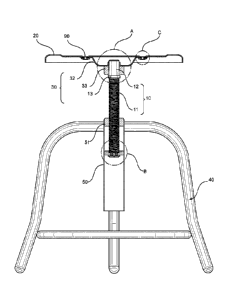
100181 With initial reference to FIGS. 1-3, according to an embodiment of the
disclosure an
anti-wobbling stool structure is provided, which includes an adjusting screw
10, a stool seat
assembly and an underframe assembly. The adjusting screw 10 includes a
threaded seat support
spindle 11 and a spindle head 12 disposed at an upper end of the threaded seat
support spindle
11.
100191 The stool seat assembly includes a stool seat 20 which is fixedly
provided at a bottom
thereof with a connecting frame 30 having a central installation hole 31. The
installation hole
31 is desirably tapered to be a cone-shaped hole. The spindle head 12
penetrates through and
is arranged in the installation hole 31, and the spindle head 12 is fittingly
engaged with the
connecting frame 30. Preferably, the spindle head 12 has a smooth outer
surface and has a taper
matching the taper of the hole 31 so as to be cone-shaped in mating
relationship with the
installation hole 31 for facilitating insertion of the spindle head 12 into
the installation hole 31
during installation. A limit boss 13 is located at a bottom of the spindle
head 12 to limit an
insertion depth of the adjusting screw 10, thus preventing excessive insertion
which might
damage the threaded seat support spindle 11 and the stool seat 20.
100201 In the depicted embodiment, the connecting frame 30 includes a
supporting plate 32
fixedly connected with the stool seat 20 and an installation bushing 33
arranged at a bottom of
the supporting plate 32. Preferably, a central portion of the support plate 32
is configured to
define a void area that defines the installation hole 31, with edges of the
support plate 32
surrounding the installation hole 31 curved upwardly to define an installation
ring 322. The
installation ring 322 is configured to fittingly receive an outer surface of
the spindle head 12.
Date recue/ date received 2022-01-25
86251273
The installation ring 322 is integrally arranged with the supporting plate 32
and has a taper
consistent with the taper of the spindle head 12.
[0021] An inner side wall of the installation tube 33 contacting the spindle
head 12 has a taper
consistent with the taper of the spindle head 12, and the installation tube 33
is in tapered fit with
the spindle head 12. When the taper of the installation ring 322 is slightly
deviated with the
taper of the spindle head 12 within a tolerance range, the stool seat 20 is
prevented from
loosening. The installation hole 31 is arranged to penetrate the supporting
plate 32 and the
installation tube 33.
[0022] During assembly of the stool, the spindle head 12 is inserted into the
installation hole
31, and the supporting plate 32 and the installation tube 33 are tightly
connected with the tapered
spindle head 12 through the tapered installation ring 322 and the tapered
inner side wall
respectively. This is advantageous to provide a large area of contact between
the stool seat
assembly and the spindle head 12 to provide a tight and reliable connection
between the stool
seat assembly and the adjusting screw 10.
[0023] Preferably, the installation tube 33 is set as a solid bushing, which
increases the strength
of the connection structure and prevents abrasion, looseness or cracking of a
connection part
between the stool seat 20 and the adjusting screw 10 after long-term use, thus
further ensuring
reliable connection. As will be appreciated, the above described structure can
be provided to
install a seat in a manner to be anti-wobbling even without the height-
adjusting aspects of the
described embodiment.
[0024] In the described embodiment, the underfrarne assembly includes a
support 40 shown
configured as three support legs which are positioned to contract the ground
or floor surface on
which the stool is placed. The underframe assembly also includes an elongate
cylindrical sleeve
or outer tube 50 located at a middle of the support 40 which is sleeved
outside the adjusting
screw 10. The outer tube50 is internally provided with a nut 51 fit with the
threaded seat support
spindle 11, the nut 51 is fixedly arranged at a top end inside the bushing 50.
[0025] With additional reference to FIG. 4, a rubber pad 60 is arranged
between the adjusting
screw 10 and the outer tube 50 and a fitting recess 61 is arranged on the
rubber pad 60. It will
6
Date recue/ date received 2022-01-25
86251273
be appreciated that the rubber pad 60 may be formed of deformable materials
other than rubber
to provide the desired padding effect A bottom of the adjusting screw 10 is
installed in the
fitting recess 61 and is in interference fit with the rubber pad 60. A movable
gap 62 is formed
between an outer wall of the rubber pad 60 and an inner wall of the outer tube
50, and the
movable gap 62 ranges from 0.070 mm to 0.250 mm. It will be appreciated that
one end of the
adjusting screw 10 is fixedly connected with the stool seat 20, the other end
of the adjusting
screw 10 is inserted into the outer tube 50, the threaded seat support spindle
11 is fit with the
nut 51 in the outer tube 50.
100261 A height of the stool seat 20 may be adjusted by rotating the adjusting
screw 10. The
adjusting screw 10 may be limited in a horizontal direction as by the rubber
pad 60 to prevent
the adjusting screw 10 and thus the stool seat from wobbling, thereby
improving the use
experience. Meanwhile, because the adjusting screw 10 is installed in the
fitting recess 61 of
the rubber pad 60 and is in interference fit with the rubber pad 60, the
rubber pad 60 may rotate
accordingly when the adjusting screw 10 is rotated. Therefore, the movable gap
62 is arranged
between the rubber pad 60 and the outer tube 50 to facilitate the rubber pad
60 to rotate and
move up and down in the outer tube 50 along with the adjusting screw 10, and
the movable gap
62 is controlled to be within a desired range of 0.070 mm to 0.250 mm.
100271 Preferably, the movable gap 62 is set as 0.1 mm, with an upper
deviation of 0.125 mm
and a lower deviation of -0.025 mm, which limits a horizontal movement and
prevents a limit
effect of the rubber pad 60 on the adjusting screw 10 from being invalid due
to too large gap,
or a friction between the rubber pad 60 and the outer tube 50 from being
increased due to too
small gap, thus being not conducive to rotation adjustment by the adjusting
screw 10, thereby
ensuring the adjusting screw 10 to be easily rotated and adjusted without
wobbling of the stool
seat 20.
100281 In the embodiment, a washer 70 is arranged at a bottom of the rubber
pad 60. Preferably,
a diameter of the washer 70 is smaller than a diameter of the rubber pad 60
and not smaller than
a diameter of the fitting recess 61. The washer 70 and the rubber pad 60 are
connected by a
plurality of bolts 80. Preferably, two bolts 80 are arranged. It can be
understood that, the rubber
7
Date recue/ date received 2022-01-25
86251273
pad 60 is in interference fit with the adjusting screw 10, when the adjusting
screw 10 moves up
and down, an acting force is exerted to the rubber pad 60, and in particular,
when the adjusting
screw 10 moves downwardly, the bottom of the adjusting screw 10 downwardly
pushes the
rubber pad 60.
[0029] Since the adjusting screw 10 is installed in the fitting recess 61 of
the rubber pad 60 and
the corresponding rubber pad 60 at the fitting recess 61 has a smaller
thickness, the rubber pad
60 is easy to be damaged under the force after long-term use. However, by
using the washer 70
to support the rubber pad 60, it is prevented that the rubber pad 60 may be
damaged under the
force and thus effectively prolonging a service life of the rubber pad 60. The
washer 70 is
fixedly connected with the rubber pad 60 through the bolts 80, thus having a
simple structure
and convenient installation, and two bolts are used to fix the washer 70, thus
preventing the
washer 70 from rotating to drive the bolts 80 to rotate, which leads to that
the bolts 80 are
loosened and fell off, and ensuring reliable connection of the washer 70.
[0030] With reference to Fig. 5, in the embodiment, the stool seat 20 and the
supporting plate
32 are connected by a plurality of rivets 90. The stool seat 20 includes
installation recesses 21
for accommodating a respective one of the rivets 90, and the supporting plate
32 is
correspondingly provided with a positioning recess 321 for accommodating the
installation
recess 21. It can be understood that the stool seat 20 and the supporting
plate 32 are riveted by
the rivets 90, thus having a simple structure and reliable connection, and
preventing the stool
seat 20 from loosening and falling off with the supporting plate 32. The rivet
90 is installed in
the installation recess 21 to enable a top end of the rivet 90 to be flush
with a surface of the
stool seat 20 to achieve a flat surface of the stool seat 20. The supporting
plate 32 is
correspondingly provided with the positioning recess 321 to be fit with the
installation recess
21, the installation recess 21 and the positioning recess 321 are in one-to-
one correspondence
during installation to facilitate installation and positioning, and a position
of the stool seat 20 is
limited in a horizontal direction to prevent the stool seat 20 from shifting
relative to the
supporting plate 32.
7a
Date recue/ date received 2022-01-25
LN-74558.US
[0031] The foregoing description of preferred embodiments for this disclosure
has been
presented for purposes of illustration and description. It is not intended to
be exhaustive or
to limit the disclosure to the precise form disclosed. Obvious modifications
or variations
are possible in light of the above teachings. The embodiments are chosen and
described in
an effort to provide the best illustrations of the principles of the
disclosure and its practical
application, and to thereby enable one of ordinary skill in the art to utilize
the disclosure in
various embodiments and with various modifications as are suited to the
particular use
contemplated. All such modifications and variations are within the scope of
the disclosure
as determined by the appended claims when interpreted in accordance with the
breadth to
which they are fairly, legally, and equitably entitled.
8
Date Recue/Date Received 2020-06-29