Note: Descriptions are shown in the official language in which they were submitted.
CA 03085940 2020-06-15
WO 2019/126187 PCT/US2018/066256
INTEGRATED CONSTRUCTION SYSTEM
CROSS-REFERENCE TO RELATED APPLICATIONS
[0001] This application is a PCT filing of and claims priority to U.S.
Patent Application No.
16/222,825, filed December 17, 2018, which is a continuation-in-part of U.S.
Patent Application
No. 15/971,620, filed May 4, 2018, which is a continuation-in-part of U.S.
Patent Application No.
15/910,698, filed March 2, 2018, which is a continuation-in-part of U.S.
Patent Application No.
15/845,962, filed December 18, 2017, all of which are incorporated herein by
reference.
BACKGROUND
[0002] This section is intended to provide background information to
facilitate a better
understanding of various technologies described herein. As the section's title
implies, this is a
discussion of related art. That such art is related in no way implies that it
is prior art. The related
art may or may not be prior art. It should therefore be understood that the
statements in this
section are to be read in this light, and not as admissions of prior art.
[0003] There are two types of concrete construction that require some form
of formwork:
vertical formwork and shoring. Vertical formwork provides the ability to form
structures that hold
vertical loads. Shoring provides the ability to form structures that hold
horizontal loads. Vertical
structures like walls, columns and foundations require formwork, and
horizontal structures like
slabs, beams and girders require shoring to cast them into place as an
elevated structural
component. Examples where shoring provides horizontal concrete members
include: slabs,
horizontal concrete girders, cross-t's under highways, etc.
[0004] Many companies in existence today have developed specific
independent formwork
systems and independent shoring systems. They generally carry a sizable
inventory of several
different types that are both rented and sold to contractors who build
concrete structures.
[0005] The applications of formwork and shoring are unlimited given the
wide range of project
types in both the industrial and commercial construction markets. From high-
rise buildings, to the
construction of an industrial facility, formwork and shoring are used to help
contractors cast
foundations, columns, walls, elevated slabs and elevated beams in an enormous
variety of shapes
and uses. Chances are that all of the buildings in which people live and work
have some sort of
poured in-place concrete that was casted using a formwork system.
[0006] Older generation systems required formwork and shoring providers to
have
significantly large inventories of parts in order to make up the variety of
configurations necessary.
Those systems consisted of endless amounts of components used by a building
contractor. Along
with the large amount of inventory items, the assembly efficiency for those
systems was often on
1
CA 03085940 2020-06-15
WO 2019/126187 PCT/US2018/066256
the low side, as compared to systems in use today. Due to the large amount of
pieces, it was
common for many of these items to be lost during the construction process.
SUMMARY
[0007] Described herein are various implementations of a fitting ring of an
integrated
construction system. In one implementation, the fitting ring includes an inner
portion configured
to be coupled to a post. The fitting ring also includes an outer portion
configured to be coupled to
a ledger rail and configured to allow the post to handle a load from the
ledger rail.
[0008] Described herein are various implementations of a modular header
beam of an
integrated construction system. In one implementation, the modular header beam
includes a first
end and a second end. The modular header beam is an extrusion configured to
interchangeably
support: shoring panels of a shoring assembly and decking panels of a decking
assembly.
[0009] Described herein are various implementations of a perimeter safety
deck assembly of
an integrated construction system. The perimeter safety deck assembly includes
a post. A first
ledger is coupled to the post in a horizontal configuration. At least one
second ledger is coupled
to the first ledger and forms a vertical outer wall.
[0010] The perimeter safety deck assembly may include a bracing element
coupled to the
post and the first ledger. The bracing element can be coupled to the post via
a ledger clamp and
the first ledger via a clip.
[0011] The vertical outer wall may include a plurality of second ledgers
coupled together to
form the vertical outer wall.
[0012] The first ledger may be coupled to the post via a ledger clamp.
[0013] The perimeter safety deck assembly may include a third ledger
coupled to the post
and the at least one second ledger. The first ledger and the third ledger may
be part of a ledger
assembly.
[0014] In one implementation, the ledger assembly may include at least one
strut coupled to
the first ledger and the third ledger.
[0015] In one implementation, the ledger assembly may include a plurality
of struts coupled
to the first ledger and the third ledger. The ledger assembly may include
brace members coupled
between adjacent struts of the plurality of struts.
[0016] In one implementation, the perimeter safety deck assembly may
include a bracing
element coupled to the post and the third ledger.
2
CA 03085940 2020-06-15
WO 2019/126187 PCT/US2018/066256
[0017] The bracing element may be coupled to the post via a ledger clamp.
[0018] The bracing element may be coupled to the third ledger via a clip.
[0019] In one implementation, a platform may be coupled to the first ledger
via a plurality of
joists. The platform may be configured to provide worker access, or provide
support for shoring
or both. The platform may support a modular header beam, the modular header
beam may be
coupled to the post and a second platform, and the second platform may be
configured to provide
shoring for a concrete slab.
[0020] Described herein are various implementations of a bearing plate of
an integrated
construction system. The bearing plate includes a surface. The surface has an
outer boundary
defining an outer edge of the bearing plate. The surface has an inner boundary
within the bearing
plate that defines an area shaped to interchangeably accommodate a plurality
of components of
the integrated construction system.
[0021] Described herein are various implementations of a bearing plate of
an integrated
construction system. The bearing plate includes a surface. The surface has an
outer boundary
defining an outer edge of the bearing plate. The surface has a plurality of
inner boundaries within
the bearing plate, each of the inner boundaries defining an area shaped to
interchangeably
accommodate a plurality of components of the integrated construction system.
[0022] Also described herein are various implementations of an integrated
construction
system. In one implementation, the integrated construction system includes a
first panel for a
formwork configuration of the integrated construction system, a second panel
for a shoring
configuration of the integrated construction system, and a third panel for a
worker access
configuration of the integrated construction system. The first panel, the
second panel and the
third panel are the same panel type.
[0023] In one implementation, the panel type may be a form panel. The form
panel may be
an aluminum form panel. In one implementation, the second panel may supported
by a header
beam in the shoring configuration. The header beam may be coupled to a
plurality of posts. The
header beam may be an aluminum header beam and the plurality of posts may be a
plurality of
aluminum posts. At least one bracing assembly may be coupled between the
plurality of posts.
The at least one bracing assembly may include a first modular ledger, a second
modular ledger,
and at least one ledger strut. The bracing assembly may include two ledger
struts and ledger
brace members.
[0024] In one implementation, the panel type may be a modular ledger. In
the shoring
configuration, the second panel may be part of a bracing assembly. The bracing
assembly may
3
CA 03085940 2020-06-15
WO 2019/126187 PCT/US2018/066256
include: the second panel, a fourth panel comprising the same panel type, and
at least one ledger
strut. The bracing assembly may include two ledger struts and ledger brace
members.
[0025] In the worker access configuration, the third panel and a fifth
panel may be part of a
second bracing assembly, the fifth panel being the same panel type. A sixth
panel may be coupled
to the second bracing assembly to form an outer wall of the worker access
configuration, the sixth
panel being the same panel type. A plurality of modular ledger panels may be
coupled together
and are coupled to the second bracing assembly to form an outer wall of the
worker access
configuration. The plurality of modular ledger panels may be coupled together
using a ledger
splice.
[0026] A plurality of joists may be coupled to a top surface of the second
bracing assembly.
The plurality of joists can support a platform that provides worker access.
[0027] Also described herein are various implementations of a method for
providing an
integrated construction system. A first panel for a formwork configuration of
the integrated
construction system is provided. A second panel for a shoring configuration of
the integrated
construction system is provided. A third panel for a worker access
configuration of the integrated
construction system is provided. The first panel, the second panel and the
third panel are a same
panel type.
[0028] Also described herein are various implementations of a modular
ledger of an
integrated construction system. In one implementation, the modular ledger
includes a rail, having
a first end and a second end. Each end of the rail is configured to be coupled
to one or more
posts and/or assemblies through a coupling component. The rail has a plurality
of holes
configured to couple to bracing components of the integrated construction
system.
[0029] The rail may be hollow and constructed of aluminum.
[0030] The coupling component may be a ledger clamp, a ledger splice, a
ledger guardrail
fitting, or a ledger end fitting.
[0031] The plurality of holes can be a hole pattern formed longitudinally
along each side of
the rail.
[0032] In one implementation, the rail may be configured to form a wall of
a safety deck.
[0033] In one implementation, the rail may be configured to form part of a
rollback mechanism.
[0034] The rail can be configured to form part of a bracing assembly when
coupled to the
bracing components.
4
CA 03085940 2020-06-15
WO 2019/126187 PCT/US2018/066256
[0035] The rail can be configured as a load bearing member when coupled to
posts of the
integrated construction system.
[0036] Also described herein are various implementations of a bracing
assembly of an
integrated construction system. In one implementation, the bracing assembly
includes a first rail
configured to be coupled to one or more posts and/or assemblies through a
first coupling
component, a second rail configured to be coupled to the one or more posts
and/or assemblies
through a second coupling component, and a first ledger strut coupled to the
first rail and the
second rail.
[0037] In one implementation, the bracing assembly includes a second ledger
strut coupled
to the first rail and the second rail. In one implementation, the bracing
assembly includes ledger
brace members coupled between the first ledger strut and the second ledger
strut. The first ledger
strut, the second ledger strut, and the ledger brace members may be adjusted
along the first rail
and the second rail. A distance between the first rail and the second rail may
be adjusted by
adjusting a lateral position of at least one of the first ledger strut and the
second ledger strut along
the first rail and the second rail.
[0038] In one implementation, the first rail and the second rail may have a
first hole pattern.
The first ledger strut may have a second hole pattern. The first hole pattern
and the second hole
pattern may be used to couple the first rail to the second rail via the first
ledger strut.
[0039] Also described herein are various implementations of an integrated
construction
system component. In one implementation, the integrated construction system
component
includes a ledger rail configured to be coupled to one or more posts and/or
assemblies through a
coupling component. The ledger rail is constructed of aluminum and configured
to provide bracing
for the integrated construction system and handle vertical loads while
attached to other
components of the integrated construction system.
[0040] Also described herein are various implementations of a modular post
of an integrated
construction system. In one implementation, the modular post includes a
longitudinal extruded
post having a first end and a second end. Each end of the longitudinal
extruded post is configured
to receive a post end component. The longitudinal extruded post includes a
plurality of grooves
cut into the longitudinal extruded post at predetermined locations along the
post.
[0041] The longitudinal extruded post may be constructed of aluminum.
[0042] The modular post may include at least one post fitting mechanically
fastened to the
longitudinal extruded post. The at least one post fitting can be coupled to
the post by sliding the
at least one post fitting down the longitudinal extruded post and twisting the
at least one post fitting
CA 03085940 2020-06-15
WO 2019/126187 PCT/US2018/066256
into place. The at least one post fitting can be twisted into place at one of
the plurality of grooves.
The at least one post fitting may be fastened to the longitudinal extruded
post using a screw.
[0043] The longitudinal extruded post may include a plurality of ribs along
the longitudinal
extruded post. The plurality of grooves can be cut into the plurality of ribs.
[0044] The post end component may include a post end fitting. The post end
fitting may be a
permanent fitting.
[0045] The post end component may include screw leg components. The screw
leg
components can be used to vary a height of a shoring assembly of the
integrated construction
system. The height of the shoring assembly can be varied within an adjustment
range.
[0046] The longitudinal extruded post can be coupled to a screw leg
assembly. In one
implementation, the screw leg assembly may remain attached to the longitudinal
extruded post
using screw leg clips of the screw leg assembly. In one implementation, the
longitudinal post and
the screw leg assembly can be configured to be moved from a first location to
a second location
without being disassembled.
[0047] The modular post can be configured to be coupled to a coupling
component of the
integrated construction system. In one implementation, the coupling component
can be coupled
to a bracing component. In one implementation, the coupling component can be
coupled to a
modular ledger panel. In one implementation, the coupling component can be
coupled to a
bracing element.
The above referenced summary section is provided to introduce a selection of
concepts in a
simplified form that are further described below in the detailed description
section. Additional
concepts and various other implementations are also described in the detailed
description. The
summary is not intended to identify key features or essential features of the
claimed subject
matter, nor is it intended to be used to limit the scope of the claimed
subject matter, nor is it
intended to limit the number of inventions described herein. Furthermore, the
claimed subject
matter is not limited to implementations that solve any or all disadvantages
noted in any part of
this disclosure.
BRIEF DESCRIPTION OF THE DRAWINGS
[0048] Implementations of various techniques will hereafter be described
with reference to the
accompanying drawings. It should be understood, however, that the accompanying
drawings
illustrate only the various implementations described herein and are not meant
to limit the scope
of various techniques described herein.
6
CA 03085940 2020-06-15
WO 2019/126187 PCT/US2018/066256
[0049] Figure 1 illustrates a shoring system using components of an
integrated construction
system in accordance with implementations of various techniques described
herein.
[0050] Figure 2 illustrates various system component drawings for modular
vertical posts and
post components in accordance with implementations of various techniques
described herein.
[0051] Figure 3 illustrates details of a post extrusion and a ledger
fitting in accordance with
implementations of various techniques described herein.
[0052] Figure 4 illustrates various views of a post end fitting in
accordance with
implementations of various techniques described herein.
[0053] Figure 5 illustrates various views of screw leg components in
accordance with
implementations of various techniques described herein.
[0054] Figure 6 illustrates various views of a multi-purpose bearing plate
in accordance with
implementations of various techniques described herein.
[0055] Figure 7 illustrates various views of a multi-purpose bearing plate
in a slope bracket
configuration in accordance with implementations of various techniques
described herein.
[0056] Figure 8 illustrates various views of a post hinge attachment in
accordance with
implementations of various techniques described herein.
[0057] Figure 9 illustrates various views of a swivel caster shoe in
accordance with
implementations of various techniques described herein.
[0058] Figure 10 illustrates different standard post assembly applications
using the multi-
purpose bearing plate in accordance with implementations of various techniques
described
herein.
[0059] Figure 11 illustrates drophead components and a configuration
showing a drophead
coupled to a modular ledger beam in accordance with implementations of various
techniques
described herein.
[0060] Figure 12 illustrates various views of a heavy duty or mega-shore
bearing plate in
accordance with implementations of various techniques described herein.
[0061] Figure 13 illustrates various system component drawings for modular
ledger panel
components in accordance with implementations of various techniques described
herein.
[0062] Figure 14 illustrates various modular ledger configuration examples
in accordance with
implementations of various techniques described herein.
7
CA 03085940 2020-06-15
WO 2019/126187 PCT/US2018/066256
[0063] Figure 15 illustrates a ledger clamp connection in accordance with
implementations of
various techniques described herein.
[0064] Figure 16 illustrates ledger rail fittings in accordance with
implementations of various
techniques described herein.
[0065] Figure 17 illustrates a ledger strut and bracing assembly range in
accordance with
implementations of various techniques described herein.
[0066] Figure 18 illustrates examples of modular header beams in accordance
with
implementations of various techniques described herein.
[0067] Figure 19 illustrates beam and joist components in accordance with
implementations
of various techniques described herein.
[0068] Figure 20 illustrates modular shoring using standard panel decking
in accordance with
implementations of various techniques described herein.
[0069] Figure 21 illustrates modular shoring using standard joist decking
in accordance with
implementations of various techniques described herein.
[0070] Figure 22 illustrates a modular shoring plan where standard aluminum
panels and filler
are used to provide shoring in accordance with implementations of various
techniques described
herein.
[0071] Figure 23 illustrates modular shoring sections and details in
accordance with
implementations of various techniques described herein.
[0072] Figure 24 illustrates various components of the integrated
construction system being
used together to form a tunnel form in accordance with implementations of
various techniques
described herein.
[0073] Figure 25 illustrates a rollback shearwall deck in accordance with
implementations of
various techniques described herein.
[0074] Figure 26 illustrates a plan view of the HD shoring application in
accordance with
implementations of various techniques described herein.
[0075] Figure 27 illustrates an elevational view of the HD shoring
application in accordance
with implementations of various techniques described herein.
[0076] Figure 28 illustrates a block diagram of a method of providing an
integrated
construction system in accordance with implementations of various techniques
described herein.
8
CA 03085940 2020-06-15
WO 2019/126187 PCT/US2018/066256
[0077] Figure 29 illustrates a post in accordance with implementations of
various techniques
described herein.
[0078] Figure 30 illustrates a coupling of a joist to a modular header beam
in accordance with
implementations of various techniques described herein.
[0079] Figure 31 illustrates standard panel assembly plan views in
accordance with
implementations of various techniques described herein.
[0080] Figure 32 illustrates elevational views of the standard panel
assembly in accordance
with implementations of various techniques described herein.
DETAILED DESCRIPTION
[0081] The integrated construction system of the present disclosure was
designed to rectify
many of the shortcomings conventional systems, including to further reduce the
amount of
components needed and maintain a high degree of versatility. In addition, the
present integrated
construction system is primarily built from non-welded lightweight aluminum
components, with
minimal steel items used for various fittings and connectors.
[0082] As stated above, prior art forming and shoring systems were designed
to be
independent. Besides the integrated construction system described in the
present disclosure and
the system disclosed in Applicant's related co-pending U.S. Patent Application
No. 15/630,923,
which is herein incorporated by reference, there is no integrated system
disclosed in the prior art
where standard elements of the integrated system can be used in both a
formwork system
configuration and a shoring system configuration. The present integrated
construction system
functions as one complete system for both vertical and horizontal aspects of
concrete
construction. The present integrated construction system can also be
configured to provide a
heavy-duty access or scaffolding system.
[0083] The present disclosure provides a shoring system that is part of a
larger integrated
construction system. This shoring system includes several key unique features
that are not found
in similar systems currently available in the market. These unique features
are outlined below.
[0084] None of the prior art individual construction systems provides a
system that provides
the aspects of formwork, shoring and provision of safe worker access during
construction. The
present integrated construction system forms part of a complete "construction
system" offering
that satisfies all three of the aforementioned aspects of construction.
[0085] In one implementation, the present integrated construction system
provides aluminum
extruded posts with mechanically fastened cast fittings. Prior art modular
aluminum shoring
systems have bracing ledger and base attachment aluminum welded fittings.
However, many of
9
CA 03085940 2020-06-15
WO 2019/126187 PCT/US2018/066256
the prior art shoring systems do not have ledger fittings and, therefore, do
not provide any capacity
for the ledgers to carry any appreciable load. The present shoring systems
provide post fittings,
e.g., cast fittings, ledger fittings or fitting rings, attached with
mechanical fasteners that are
designed to carry loads for multiple situations.
[0086] In one implementation, the present integrated construction system
provides a
multipurpose aluminum and steel modular ledger. The ledgers may be made from a
hybrid of
aluminum and steel components vs. welded aluminum.
[0087] The ledgers can be configured into a variety of assemblies for a
multitude of
applications vs. static sized bracing panels. The ledgers are designed to act
as a truss or load
bearing member (e.g., vertical or other types of loads) vs. being used solely
as a bracing and
spacing member.
[0088] The ledger post connections have a removable series of end
connections for various
uses. The ledger post connections are not permanently mounted and are designed
for multiple
purposes as opposed to being designed for a single purpose.
[0089] The modular ledger is designed to be useable as: a bracing/spacing
panel between
vertical posts; a headload or truss shoring member that can hold up shoring
loads in a variety of
situations; an access platform for vertical shearwall construction; a roof
truss system for large
enclosures; and a perimeter safety deck system for construction worker access.
[0090] In one implementation, the present integrated construction system
provides safety
deck solutions for worker access. Safe construction worker access is an
important aspect of all
high-rise concrete construction projects. The present integrated construction
system provides safe
worker access to the outer perimeter of floor slab construction during all
phases of: a floor pour,
shoring setup, slab pour, post-tensioning slab cables, and continuous setup of
the next level of
shoring. Prior art systems use the actual slab shoring structure to give
workers access to the
perimeter of the top floor under construction. The problem with the prior art
is that once the shoring
is stripped, there is no effective means of access to the outer perimeter of a
previously constructed
floor slab. The issues present in prior art worker access slow down the
construction cycle. The
present integrated construction system provides perimeter deck access that is
provided using
components of the integrated construction system but independent of the
shoring deck itself, to
give worker access to the outer perimeter of the work. This allows the lower
level access to remain
in place to allow workers continued perimeter access to lower levels, while
the upper level
construction continues.
[0091] In one implementation, the present integrated construction system
provides
applications for heavy duty access. Conventional scaffolding systems are
generally used to give
CA 03085940 2020-06-15
WO 2019/126187 PCT/US2018/066256
workers access to general construction tasks. However, when the applications
become extremely
high or when the system incurs higher than normal loading conditions, other
means of worker
access are generally required. The present integrated construction system is
able to provide
worker access in higher than normal loading situations, while still meeting
all OSHA access
regulations.
[0092]
In one implementation, the present integrated construction system provides
heavy duty
enclosures.
Enclosures or containment structures are a common form of providing
environmentally controlled spaces when critical construction processes require
weather or other
forms of climate protection. When these enclosure structures become large or
subjected to high
external forces, such as wind, most conventional scaffolding systems do not
have the ability to
perform in these high external force conditions. The present integrated
construction system is able
to sustain higher than normal loads and can be configured to provide larger
than normal
containment structures.
[0093]
In one implementation, a mega-shore application is provided. Most prior art
shoring
systems have either a light or medium duty rating. Other prior art shoring
systems may have
heavy or very heavy-duty ratings. No prior art system can function across all
rating ranges. Posts
coupled to a mega-shore bearing plate can be configured in a variety of ways
to achieve each
level of duty rating. This includes the ability to cluster posts in groups to
achieve very high loads
in excess of 100,000 lbs. per shore location.
[0094]
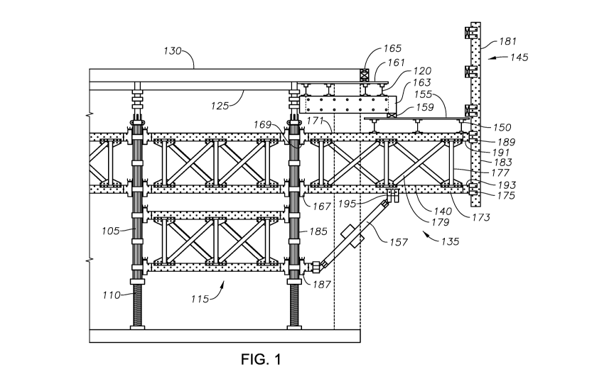
FIG. 1 shows a configuration providing a shoring application using components
of an
integrated construction system. FIG. 1 shows primary shoring components:
aluminum posts 105,
aluminum adjustable screw legs 110, aluminum and/or steel ledger assemblies
115, aluminum
header beams (not shown), and aluminum joists 120. The primary components are
constructed
and assembled together without using any aluminum welding. The primary
components of the
shoring configuration are designed for multiple uses and are also designed for
integration with
formwork components of the integrated construction system. For example, the 6
foot panels 125
used to form slab 130 are configured for use in both formwork and shoring
applications. As
detailed further below, other components in addition to the primary components
are included to
provide additional applications for roll-back formwork, mega-shoring,
perimeter safety deck
systems, and heavy duty access systems.
[0095]
An example of a perimeter safety deck system 135 is also shown in FIG. 1. This
example perimeter safety deck for worker access includes a ledger assembly 140
and a plurality
of ledger rails coupled together to form an outer wall 145 (although multiple
ledger rails 181, 183
are shown in this example, a single ledger rail may also be used to form the
outer wall). In this
example, ledger assembly 140 includes ledger rails 171, 173 and includes
struts 177 and brace
11
CA 03085940 2020-06-15
WO 2019/126187 PCT/US2018/066256
members 179. The ledger assembly 140 is coupled to post 185 using ledger
clamps 167, 169.
Ledger assembly 140 is coupled to ledger rails 181, 183 using ledger end
fittings 191, 193 and
accessory clips 175, 189. Ledger assembly 140 may be supported by bracing
element 157.
Bracing element 157 may be coupled to ledger 173 using an accessory clip 195.
Bracing element
157 may also be coupled to the post 185 using ledger clamp 187. Although a
plurality of struts
177 and brace members 179 are shown, certain implementations may include or
omit ledger 140,
struts 177 and brace members 179.
[0096] Although the ledger assembly includes multiple ledger rails 171,
173, certain
implementations may include only one horizontal ledger rail, e.g., ledger rail
171, coupled to post
185 and outer wall 145. In implementations where bracing is utilized, ledger
rail 171 may be
supported by bracing element 157. In this implementation, bracing element 157
can be coupled
directly to ledger rail 171 using clip 195 and coupled to a fitting of post
185 using clamp 187.
[0097] In the example shown in FIG. 1, joists 150 are coupled to the
bracing assembly and
are used to support a platform 155, e.g., a wood platform. Platform 155 may
provide support for
shoring in addition to providing worker access via a perimeter safety deck.
Platform 155 may
support a modular header beam 163 coupled to joists 120, which in turn support
a platform 161
and barrier 165. The platform 161 and barrier 165 are used to form an outer
edge of the concrete
slab 130. In some implementations filler 159 may be included to keep modular
header beam 163
and platform 161 level.
[0098] Joists 120, 150 may be coupled to a modular header beam or a ledger
rail (e.g.,
modular header beam 163 or ledger rail 171) using a metal clip that holds a
nut and bolt. The
head of the bolt slides into a groove along the bottom of the joist 120, 150
and the metal clip
connects to either the modular header beam or the ledger rail/panel. Once the
clip is in place, the
bolt is tightened to connect both members (the joist and the modular header
beam or the ledger
rail) together.
[0099] The coupling of a joist to a modular header beam is shown in more
detail in FIG. 30.
FIG. 30 shows a joist 1920 coupled to a shoring assembly 3001 that includes a
modular header
beam (header extrusion 1003), multi-purpose bearing plate 1008, eye-bolt
connector 1040, post
end fitting 1016, and a post 1002 having post end fittings 215. Joist 1920 is
coupled to the shoring
assembly 3001 using standard joist clip 3010 as described above.
[00100] The coupling of a joist to a ledger is also shown in more detail in
FIG. 30. FIG. 30
shows a joist 1920 coupled to a modular ledger panel 3002 using joist/ledger
clip 3005.
[00101] FIG. 2 includes various system component drawings for modular
vertical posts 205
that include post components 210, 215 of the shoring system. The modular
vertical posts 205
12
CA 03085940 2020-06-15
WO 2019/126187 PCT/US2018/066256
may be provided in various lengths. In one implementation, the modular
vertical posts 205 have
lengths of 2 feet, 3 feet, 4 feet, 6 feet and 9 feet. Each of the posts 205 is
made up of a longitudinal
extruded post 210 and independent fittings, e.g., ledger fitting 215, that are
fastened to the post.
The independent fittings are not welded to the post. The independent fittings
are, instead,
mechanically fastened. The fittings are coupled to the post by sliding the
fitting down the post,
twisting the fitting into place and mechanically fastening the fitting to the
post. The fitting is twisted
into place using a groove 207 lathed into the ribs of the post 205. The groove
207 is obscured by
the fitting 215.
Fittings are placed onto the post at predetermined intervals. In one
implementation, fittings fastened to the post are placed 12 inches apart.
[00102]
FIG. 29 illustrates a post without fittings. Post 2905 includes ribbed
portions 2925,
2930, 2935, 2940 and grooves 2910, 2915, 2920. The post is formed as a
longitudinal extrusion
having ribs. The grooves 2910, 2915, 2920 are lathed/cut into the ribs of the
post 2905 at
predefined intervals resulting in the post having the grooves 2910, 2915, 2920
and the ribbed
portions 2925, 2930, 2935, 2940. As described above, the fittings are coupled
to the post by sliding
them down the ribbed portions 2925, 2930, 2935, 2940 of the post. The fittings
are then twisted
into place using grooves 2910, 2915, 2929.
[00103]
Screw legs 255 are provided in various lengths and are used to adjust a height
of the
vertical post. The height of the post may be adjusted by using the screw legs
on one or both ends
of the vertical post. The bearing plate 220, mega-shore bearing plate 225,
slope bracket 230,
post hinge 235, screw leg connector clips 240, swivel caster shoe 245, and
deck drophead 250
are used with the vertical posts to provide various shoring application
configurations. FIG. 2
further includes a side view of one configuration of a shoring assembly 260
using vertical posts
265, screw legs 270, the ledger panel assembly 275, bearing plates 280, a
header beam 285, and
joists 290.
[00104]
FIG. 3 shows details of a post extrusion, and a ledger fitting.
Implementations of the
integrated construction system may refer to a modular vertical post (e.g.,
modular vertical post
210), a post (e.g., post 305) and a post extrusion (e.g., post extrusion 1525)
interchangeably.
Implementations of the integrated construction system may also refer to a
ledger fitting (e.g.,
ledger fitting 215), a post ledger fitting (e.g., post ledger fitting 1530),
and a fitting ring (e.g., fitting
ring 307) interchangeably. FIG. 3 shows a cross-sectional view of post 305.
Post 305 is an
extruded aluminum post. Also shown is a fitting, e.g., fitting ring 307.
Fitting ring 307 is used to
attach a ledger or ledger assembly to post 305. Ledgers and ledger assemblies
are described in
more detail below in FIGs. 13-17. In one implementation, the fitting ring 307
is spaced every 12
inches along the post 305.
13
CA 03085940 2020-06-15
WO 2019/126187 PCT/US2018/066256
[00105] As also described above in FIG. 2, the fitting ring 307 is slid
down the post 305 and
then twisted into place on the post 305. After twisting the fitting ring 307
into place on the post
305, the fitting ring 307 is mechanically fastened to the post, e.g., with a
screw. The feature is
unique to this system, as all others weld connection fittings to the posts
[00106] The post 305 is configured to be a complete extruded piece, e.g.,
constructed of
aluminum. The post 305 is cut to a specific length. A groove, e.g., groove
207, is lathed into the
circumference of the post 305 at predetermined locations along the post 305.
In one
implementation, the groove is lathed into the post 305 every 12 inches. In one
implementation,
the groove is a 1/2 inch cut groove. The fitting ring 307 slides down the post
305 and twists into
place at each groove. View 320 shows the fitting ring 307 being twisted into
the groove, which is
shown in FIG. 29. View 320 shows a circular shaft portion 335 of the post 305.
View 320 also
shows an outer rib portion 337 of the post 305 that remains below the groove.
The groove is cut
on the vertical ribs of the extrusion, not on the circular shaft. In one
implementation, screws may
fasten the fitting ring 307 into place to prevent them from moving.
[00107] View 310 and 315 are top and side views of the fitting ring 307,
respectively. As
previously described, the rings are twisted into place as shown in view 320
and mechanically
fastened as shown in view 325, e.g., using screw 330.
[00108] As shown in FIG. 29, there are grooves 2910, 2915, 2920 that are
cut into the post
extrusion 2905. Protrusion 343 of fitting ring 307 fits into the groove 2910,
2915, 2920. Once
fitting ring 307 is placed onto post extrusion 2905, screws 330 are used to
hold the fitting ring 307
in place on the post extrusion 2905. The screws 330 that hold the fitting ring
307 in place are
seated through hole 339. Optional hole 341 can be used for future attachments,
such as lateral
plan bracing or cable bracing.
[00109] Configuring posts in the manner described above allows for the
installation of posts
and ledgers without welding. In addition, configuring posts in this manner
further allows posts to
take a load. Prior art systems don't allow a ledger to put a load from a
ledger onto a post.
[00110] FIG. 4 and FIG. 5 include post end components. The post end
components may
include the post end fitting of FIG. 4 and/or the screw leg components of FIG.
5.
[00111] FIG. 4 shows various views 405, 410, 415, 420 of a post end
fitting. View 405 is a top
cross-sectional view of a post end fitting. Views 410, 415, 420 are top cross-
sectional, side cross-
sectional, and side view respectively, of a post end fitting coupled to a
post. The post end fitting
can be used on a top portion and a bottom portion of each post. In one
implementation, the post
end fitting is configured to be a permanent fitting.
14
CA 03085940 2020-06-15
WO 2019/126187 PCT/US2018/066256
[00112] FIG. 5 shows various views 505, 510, 515 of screw leg components.
One portion of
FIG. 5 shows a side view 505 of a post and screw leg assembly. This view shows
a screw leg
end fitting 520, a screw leg thread 525, a screw leg adjusting nut 530, screw
leg connector clips
535, a post end fitting 540, and an aluminum post 545. The screw leg connector
clips 535 allow
the screw leg 520, 525, 530 to attach to the post end fitting 540 and fly with
the post after a pour.
[00113] Shoring is generally used repetitively from one concrete pour to
the next. In typical
prior art shoring systems, the shoring system is completely disassembled and
then re-assembled
on the next position. The present integrated construction system provides the
ability to keep much
of the setup intact and fly the assembly with a crane from one setup to the
next to reduce labor
costs. The screw leg clips allow the screw legs to remain attached to the
posts, so the screw legs
will still turn for adjustment, but also provide the ability to move the post
and screw leg as a unit
from one pour to the next without being disassembled.
[00114] Another portion of FIG. 5 shows a top view 510 of a screw leg end
fitting. Another
portion of FIG. 5 shows a side view 515 of the screw leg end fitting. The
screw leg assembly 520,
525, 530 is used to vary the height of the shoring assembly, e.g., shoring
assembly 260. A portion
of the screw leg assembly 520, 525, 530 fits inside of the post 545.
Adjustable legs, e.g., screw
legs, are used to provide a height needed for a particular application, e.g.,
within an adjustment
range. The screw leg thread 525 is used with a screw leg end fitting 520 and a
screw leg adjusting
nut 530. In one implementation, the screw leg adjusting nut 530 can be a
twisted wing nut. The
configuration shown in FIG. 5 allows for an adjustable post having non-welded
components.
[00115] FIGs. 6-10 show a multi-purpose bearing plate in various
configurations. In one
implementation, the multi-purpose bearing plate 602 is constructed of
aluminum. The multi-
purpose bearing plate may bear on a concrete floor or a sill designed from
wood if the shoring
assembly is placed over earth fill. FIG. 6 shows various views 605, 610, 615,
620. View 605 is a
top view of the multi-purpose bearing plate 602. A top surface of multi-
purpose bearing plate 602
has an outer boundary defining an outer edge of the bearing plate. In one
implementation, the
outer edge includes a plurality of indentations 630. Indentations 630 are used
to couple a header
beam or other post fittings using a connecting screw. The use of indentations
630 is shown more
clearly in FIG. 10 where the eye-bolt connector 1040 is used to couple the
multi-purpose bearing
plate 602 for various applications. The top surface of multi-purpose bearing
plate 602 has an
inner boundary 624 within the multi-purpose bearing plate 602 that defines an
area 634 shaped
to interchangeably accommodate a plurality of components of the integrated
construction system.
A plurality of members 628 are formed on an outer surface of the inner
boundary 624. The plurality
of members 628 give added bending capacity between the multi-purpose bearing
plate 602 and
the post end fitting 617. A plurality of openings 626 are formed within the
area 634. The openings
CA 03085940 2020-06-15
WO 2019/126187 PCT/US2018/066256
626 are used to couple the multi-purpose bearing plate 602 to other components
of the integrated
construction system.
[00116] View 610 is a side view of the multi-purpose bearing plate and
screws 612 that are
used to couple the bearing plate 602 to other components of the shoring
system. Screws 612
pass through holes 626 and screw into the post end fitting 617 or screw leg
end fitting 622. View
615 is a side view of the multi-purpose bearing plate coupled to a post end
fitting 617. Post end
fitting 617 is coupled to a portion of a post 632. View 620 is a side view of
the multi-purpose
bearing plate 602 coupled to a screw leg end fitting 622. The multi-purpose
bearing plate 602 can
be used on a top portion of a shoring assembly and/or a bottom portion of a
shoring assembly.
[00117] FIG. 7 shows various views 705, 710, 715 of a multi-purpose bearing
plate 602 in a
slope bracket configuration. The multi-purpose bearing plate 602 is coupled to
the slope bracket
707 using screws 612. The slope bracket 707 is also coupled to screw leg 702
using screws 706.
View 705 is a view of the slope bracket configuration showing a front/rear
portion of the slope
bracket 707. View 710 is a view of the slope bracket configuration showing a
side view of the
slope bracket 707. View 715 is a plan view of the slope bracket. The slope
bracket configuration
is utilized in sloped surface applications or sloped beam applications.
[00118] FIG. 8 shows various views of a post hinge attachment. View 805
shows a bottom
plate of a post hinge assembly. View 810 shows a post hinge assembly, which
includes a top
plate 825, the bottom plate 805, a barrel 830, and a screw fastener 835 and
screw 840. View 815
shows the post hinge assembly with posts 845, 850 in an open state. View 820
shows the post
hinge assembly with posts 845, 850 in a closed state. The post hinge assembly
is useful in moving
shoring components.
[00119] FIG.9 shows various views 905, 910, 915 of a swivel caster shoe.
Swivel caster shoes
can be mounted to a post assembly 917 using the multi-purpose bearing plate
922. View 905
shows one implementation of a swivel caster shoe 935 coupled to a post
assembly 920 and a
screw leg assembly 925 using a multi-purpose bearing plate 930. View 910 is a
top view of the
swivel caster shoe. View 915 is side view of the swivel caster shoe.
[00120] FIG. 10 shows views 1005, 1010, 1015, 1020 of different standard
post assembly
applications using the multi-purpose bearing plate. In other words, the same
multi-purpose
bearing plate can be used for different applications. The prior art uses
different bearing plates for
different applications.
[00121] View 1005 shows a sloped slab application. In one implementation,
the sloped slab
application includes a slope bracket 1001. The slope bracket 1001 is coupled
to multi-purpose
16
CA 03085940 2020-06-15
WO 2019/126187 PCT/US2018/066256
bearing plate 1008 using screws 1027. Slope bracket 1001 is also coupled to
screw leg 1006
using screws 1029. Screw leg 1006 is further coupled to post 1002.
[00122] View 1010 shows a screw leg and header beam application. In this
configuration,
screw leg 1006 is coupled to post 1002. Screw leg 1006 is also coupled to
multi-purpose bearing
plate 1008, e.g., using screws 1027 (not shown). Multi-purpose bearing plate
1008 is coupled to
header extrusion 1003 using eye-bolt connector 1040.
[00123] View 1015 shows an application where a header beam is directly
coupled to the post.
In this configuration, post 1002 is coupled to post end fitting 1016. Post end
fitting 1016 is also
coupled to multi-purpose bearing plate 1008, e.g., using screws 1027 (not
shown). Multi-purpose
bearing plate 1008 is coupled to header extrusion 1003 using eye-bolt
connector 1040.
[00124] View 1020 shows an application where two posts are coupled
together. In this
configuration, post 1002 is coupled to post end fitting 1016. Post end fitting
1016 is also coupled
to multi-purpose bearing plate 1008, e.g., using screws 1027 (not shown). Post
1013 is coupled
to post end fitting 1017. Post end fitting 1017 is also coupled to multi-
purpose bearing plate 1019,
e.g., using screws 1027 (not shown). Multi-purpose bearing plate 1008 is
coupled to multi-
purpose bearing plate 1019 using eye-bolt connector 1040.
[00125] As shown in the various views, the modular posts can be used with
the same multi-
purpose bearing plate to provide different applications.
[00126] FIG. 11 shows drophead components 1105 and a configuration 1110
showing a
drophead 1102 coupled to a modular ledger beam 1107. Drophead components 1105
include a
drophead top plate 1112, a drophead base plate 1114, a drop head inner tube
1116, a drop head
header seat 1118, and a drophead stripping nut 1120. The drophead 1102
provides the ability to
drop the shoring and leave the posts in place for reshoring. The drophead
components mount to
the end of a post or screw leg.
[00127] FIG. 12 shows various views 1205, 1210, 1215, 1220 of a heavy duty
or mega-shore
bearing plate. View 1205 is a top view of a mega-shore bearing plate 1202. In
one
implementation, the mega-shore bearing plate 1202 is constructed of steel. The
mega-shore
bearing plate 1202 may be coupled to a beam or a modular header beam (e.g.,
modular header
beam 1912) near a top portion of a shoring assembly using a metal clip, e.g.,
standard joist clip
3010. A top surface of mega-shore bearing plate 1202 has an outer boundary
defining an outer
edge of the bearing plate. The top surface of mega-shore bearing plate 1202
has a plurality of
inner boundaries 1224, 1234, 1236, 1238 within the multi-purpose bearing plate
1202. Each inner
boundary 1224, 1234, 1236, 1238 defines an area 1240, 1242, 1244, 1246 shaped
to
interchangeably accommodate a plurality of components of the integrated
construction system. A
17
CA 03085940 2020-06-15
WO 2019/126187 PCT/US2018/066256
plurality of members 1226, 1248, 1250, 1252 are formed on an outer surface of
each inner
boundary 1224, 1234, 1236, 1238. The plurality of members 1226, 1248, 1250,
1252 are the
seats where the post end fittings, e.g., post end fitting 617, are mounted to
the mega-shore bearing
plate 1202, e.g., using screws 612. A plurality of openings 1224, 1254, 1256,
1258 are formed
within each area 1240, 1242, 1244, 1246. The openings 1224, 1254, 1256, 1258
are used to
couple the bearing plate 1202 to other components of the integrated
construction system.
[00128] View 1210 is a side view of the mega-shore bearing plate 1202. View
1215 is a top
view of the mega-shore bearing plate 1202 with posts 1228, 1260, 1262, 1264
installed within
areas 1222, 1234, 1236, 1238, respectively. View 1220 is a side view of the
mega-shore bearing
plate 1202 with posts 1232, 1266 and screw legs 1230, 1268 installed.
[00129] The mega-shore or heavy duty bearing plate is used to cluster legs
together to handle
a very heavy duty load. The heavy duty bearing plate may also be referred to
as a high capacity
bearing plate. The mega-shore bearing plate accommodates more than one post.
In one
implementation, the mega-shore bearing plate can accommodate a cluster of four
posts.
[00130] FIGs. 13-17 show various configurations for modular ledger panels.
FIG. 13 includes
various system component drawings for modular ledger panel components.
Aluminum ledger
rails 1305 of various lengths are shown. The aluminum ledger rails are hollow
and can be from 1
foot to 9 feet long. Each ledger rail 1305 includes a plurality of holes
placed longitudinally along
each side of the rail. The plurality of holes are placed along the rail in a
hole pattern. The hole
pattern allows other components, e.g., bracing components, and assemblies,
e.g., bracing
assemblies, to be attached to each rail. Bracing components may include one or
more ledger
struts 1340. In some implementations, bracing components may include more than
one ledger
strut and at least two ledger brace members. Example bracing assemblies 1310,
1315, 1320,
1325 are also shown. The bracing assemblies include top 1330 and bottom 1335
ledger rails,
ledger struts 1340 (e.g., steel ledger struts) and ledger brace members 1345.
Also shown is a
double ledger clamp assembly 1350 for 12 inch post spacing, a ledger clamp
1355, a ledger splice
1360, a ledger clamp/end assembly 1365, a ledger guardrail fitting 1370, and a
ledger end fitting
1375. When end clamps, e.g., ledger clamps 1355, are coupled back to back and
coupled to a
post on each side, 12 inch spacing is provided from center to center of the
posts. Coupling
components, e.g., components 1355, 1360, 1370, 1375, may be used to couple the
rails 1305 to
other components, e.g., rails, posts, and/or assemblies of the integrated
construction system. In
addition, a standard accessory clip 1380 and a standard clamp 1385, both of
which are disclosed
in co-pending U.S. Patent Application No. 15/630,923, can be used with the
ledger rails and
bracing assemblies of the present disclosure. Ledger clamp/end assembly 1365
may be used to
couple standard accessory clip 1380 or standard clamp 1385 to the end of a
ledger. The ledger
clamp assembly 1365 includes ledger clamp 1355 and ledger end fitting 1375
mated together.
18
CA 03085940 2020-06-15
WO 2019/126187 PCT/US2018/066256
The ledger clamp assembly 1365 and standard accessory clip 1380 can be used
for both formwork
and shoring applications of the integrated construction system.
[00131]
In one implementation, the standard accessory clip 1380 and the standard clamp
1385
can be used to connect formwork components to the ledger rail 1305. In one
implementation, the
standard accessory clip 1380 and the standard clamp 1385 are used for a one-
sided formwork
application.
In one implementation, no ties are used for one-sided formwork. .. In this
implementation, the ledger and posts become the lateral bracing for the
formwork panels.
[00132]
FIG. 14 shows various modular ledger configuration examples 1405, 1410, 1415,
1420, 1425, 1430, 1435, 1440, 1445, 1450, 1455, 1460. Typical bracing
assemblies are shown
for various lengths from 1 foot to 10 feet. The bracing assemblies may be
configured to
accommodate light duty (LD) and heavy duty (HD) configurations. Examples of
LD, HD and
standard duty configurations are shown in items 1450, 1455 and 1460,
respectively. Struts can
be added or removed and the cross-brace size can be changed. Load capacity can
be adjusted
by adding or removing bracing components.
[00133]
FIG. 15 shows a ledger clamp coupled to a post ledger fitting. A ledger rail
1505 is
coupled to a ledger clamp 1510 using ledger connectors 1515. The ledger clamp
1510 is coupled
to the post extrusion 1525 using a post ledger fitting 307, 1530 that is
attached to the post
extrusion 1525 using a groove 1535.
[00134]
Ledger clamp 1510 is part of the ledger assemblies. Ledger clamp 1510 is the
same
part as coupling component 1355 and is also shown in modular ledger
configuration example
1450. The jaws at the end of the ledger clamp 1510 fit over the top and bottom
of the post ledger
fitting 307, 1530 and tighten in-place using the adjusting screw on the ledger
clamp. This
connection allows a load to be transferred from the ledger 1505 to the post,
via the post ledger
fitting 1530.
[00135]
In configurations where the post 305, 1525 handles a load from a ledger rail,
the post
305, 1525 is coupled to a ledger rail 1505 via post ledger fitting 1530 and
ledger clamp 1510.
The ledger rail 1505 can be configured to act as a truss or a load bearing
member (e.g., vertical
or other types of loads) when coupled to the post 305, 1525. An inner portion
of the post ledger
fitting 307, 1530 is configured to be coupled to the post 305, 1525, e.g.,
using groove 1535 and a
mechanical fastener (e.g., screw 330). An outer portion of post ledger fitting
307, 1530 is
configured to be coupled to the ledger rail 1505 and configured to allow the
post 305, 1525 to
handle a load from the ledger rail 1505.
[00136]
FIG. 16 shows ledger rail fittings. Views 1605, 1610 show ledger rail fittings
clamped
together in configurations where a ledger in a horizontal position 1615, 1620
is clamped to a ledger
19
CA 03085940 2020-06-15
WO 2019/126187 PCT/US2018/066256
in a vertical position 1625, 1630 using an accessory clip 1635 with an
attached ledger end fitting
1640 (view 1605) and a double accessory clip 1645 with an attached guard rail
fitting 1650 (view
1610). Also shown is a front/rear view of a ledger tube 1655, a ledger splice
1660, and a front/rear
view of a ledger splice 1665.
[00137] In one implementation, ledger rail fittings provide the ability to
add a vertical guardrail
to the end of a cantilevered ledger. In this implementation, the cantilevered
ledger is decked for
worker access. The ledger rail fittings allow a guardrail to be installed on
the perimeter for worker
safety, e.g., to prevent falling.
[00138] FIG. 17 shows a ledger strut and bracing assembly range. The ledger
strut 1707 and
ledger brace members 1712 are longitudinally adjustable along a pair of ledger
rails 1717 in a
bracing assembly 1705. Hole patterns in the ledger struts 1715 and the ledger
rails 1710 allow
different spacing. In one implementation, the hole patterns are punched into
the rails at the time
of manufacture. The ledger struts 1707 and ledger brace members 1712 in this
example
configuration can be adjusted along the rails using the hole patterns 1710,
1715. In addition,
spacing between the bracing can be adjusted using the hole patterns present on
the ledger rails
1717 and ledger strut 1707. Also shown in FIG. 17 are a ledger end view 1720,
a ledger brace
1730, an exploded ledger end view 1725, a strut connector 1740 and a brace
connector 1735.
[00139] In one implementation, different spacing between the ledger rails
in a bracing assembly
can be achieved by using differently sized brace members 1712 with the ledger
struts 1707. In
one implementation, different spacing can also be achieved by adjusting
lateral spacing between
two ledger struts that are coupled to a brace member. In this implementation,
moving ledger struts
closer together or further apart and adjusting a coupling location for the
brace members along the
hole pattern of the ledger struts allows for different spacing to be achieved
between the ledger
rails.
[00140] FIG. 18 shows examples of modular header beams. Header beams 1805
may have
lengths of 4 feet, 6 feet, 8 feet, and 10 feet are shown. In addition, a 3
foot header splice 1810 is
shown. The modular header beams, which can be used for a drop deck shoring
application are
extruded out of aluminum and use modular fittings to attach to the drop deck
panels. In addition,
the modular header beams can be used without the fittings as open beams. When
used as an
open beam, e.g., a header beam, capacity can be increased and provides the
ability to accept a
higher load.
[00141] In one implementation, standard aluminum form panels used in a drop
deck shoring
application can be easily stripped from the finished concrete pour while
leaving the shoring posts
in place as re-shoring for the next elevated pour. Re-shoring is used to
support fresh concrete
floor slabs from underneath while shoring is placed on top for the next
elevated floor slab pour.
CA 03085940 2020-06-15
WO 2019/126187 PCT/US2018/066256
[00142]
FIG. 19 shows beam and joist components. FIG. 19 shows a side cutaway view
1905
of a modular header connector fitting 1903. Modular header connector fitting
1903 includes a
plurality of hooks 1909 and a plurality of openings 1907. Modular header
connector fitting 1903
is shaped to fit within modular header beam 1912. Modular header connector
fitting 1903 may be
coupled to the modular header beam 1912 via openings 1907. FIG. 19 also shows
a view 1910
of a header extrusion, e.g., header beam 1912, with modular header connect
fitting 1903 inserted
within the header beam 1912. Header beam 1912 includes various openings 1927,
1928, 1929,
1930, 1931, 1932 used to couple the header beam to other components of the
integrated
construction system. FIG. 19 further shows a view 1915 of a joist 1920 with a
synthetic nailer
1925.
[00143]
FIG. 19 shows a cross section of the modular header beam 1912. Openings 1927,
1928, 1929, 1930, 1931, 1932 are long grooves when the modular header beam
1912 is extruded
as a long member. The grooves are used to couple various metal clips, for
example, as described
above with respect to FIG. 1. An aluminum joist, e.g., joist 1920, 1935, 1940,
1945, may be
coupled to modular header beam 1912 using a metal clip with a nut and bolt. In
one
implementation, the head of the bolt slides into the groove of the header beam
and the clip can
be coupled to the joist. In one implementation, a panel clip, e.g., panel clip
2056, may be coupled
to the sides of the modular header beam 1912 to hold formwork panels in place
when used for
shoring a concrete slab.
[00144]
FIG. 20 shows modular shoring using standard panel decking. Item 2005 is a
side
view of a shoring configuration that uses a post 2015, deck drop head assembly
2020, and a
modular header beam 2025 to support standard aluminum form panels 2030, and
plywood filler
2035 in a shoring application.
Deck drop head assembly 2020 includes a plurality of
couplings/fittings made into an adjustable assembly, shown in figure 11, as an
exploded view item
1105 with individual items 1112, 1114, 1116, 1118, 1120 and an assembled view
item 1102. This
is the same as figure 20 with items 2007, 2008, 2009, 2011 and 2020.
Couplings/fittings 2007,
2009, 2011 are welded to a sleeve 2008 or 2020. The sleeve 2008 is slide-ably
engaged with an
inner tube 2006. An adjusting nut, figure 11, item 1120, of the deck drop head
assembly 2020
has two settings. The first setting occurs when the deck drop head assembly
2020 is set in place
prior to a concrete pour, as shown in FIG. 20. Once the concrete slab is
poured and hardens, the
nut of the deck drop head assembly 1120 is twisted 90 degrees so that the
sleeve 2008 drops
downward. The header beam 1912, deck panels 2030, 2032 and filler 2005 drop as
well and can
be stripped out and set for later use. In this implementation, the post 2015
may remain in place
as re-shoring and another set of posts may be installed on the next floor
level. The stripped deck
panels 2030, 2032 and header beams 1912 can then be installed on the next set
of posts so that
the next flour slab can be poured. This process may be repeated until all
floors have been poured.
The plurality of couplings 2007, 2009, 2011 are shaped to accommodate the
plurality of hooks
21
CA 03085940 2020-06-15
WO 2019/126187 PCT/US2018/066256
1909 of the modular header connector fitting 1903. The modular header beam
1912 is coupled
to the deck drop head assembly 2020 via modular header connector fitting 1903
and supports
standard aluminum form panels 2030, 2032. In this implementation, deck drop
head assembly
2020 supports plywood filler 2035. The standard aluminum form panels 2030,
2032 are useable
for both formwork and shoring applications.
[00145] View 2010 is a view in a span direction of the modular header beam
1912 holding up
standard aluminum panels 2045, 2047. Form alignment plates 2050, 2052 are used
to connect
the modular header beam 1912 to the standard panels 2045, 2047. Deck panel
clip 2054 is used
to couple modular header beam 1912 to standard aluminum panel 2047. Deck panel
clip 2056 is
used to couple modular header beam 1912 to standard aluminum panel 2045. Deck
panel clips
2054, 2056 are used to couple the header beam to other components using
grooves 1927, 1928,
1929, 1930, 1931, 1932 as described above with respect to FIG. 19.
[00146] FIG. 21 shows modular shoring using standard joist decking. Item
2105 is a side view
of a shoring configuration that uses a post 2015, deck drop assembly 2020, and
a modular header
beam 1912 to support joists 1920, 1935, 1940, 1945 holding up plywood deck
material 2135.
Deck drop head assembly 2020 includes a plurality of couplings 2007, 2009,
2011. The plurality
of couplings 2007, 2009, 2011 are shaped to accommodate the plurality of hooks
1909 of the
modular header connector fitting 1903. The modular header beam 1912 is coupled
to the deck
drop head assembly 2020 via modular header connector fitting 1903 and supports
the plywood
deck material 2135 using joists 1920, 1935, 1940, 1945 and deck drop head
assembly 2020.
Joists 1920, 1935, 1940, 1945 may be coupled to the plywood deck material 2135
using synthetic
nailers 1925, 1950, 1955, 1960.
[00147] The standard panels 2030, 2032 of FIG. 20 are 4" deep. The joists
1920, 1935, 1940,
1945 of FIG.21 are 6.5" deep. In addition, 0.5" thick plywood sits on top of
joists 1920, 1935,
1940, 1945. In this implementation, a joist and plywood configuration has a
total depth of 7". The
difference between the standard panel configuration of FIG. 20 and the
joist/plywood configuration
is 3". The three fittings 2007, 2009, 2011 on the drophead attachment 2020 are
spaced 3" apart.
Because of the difference in depth of the two configurations (FIG. 20 and FIG.
21), header beam
1912 is coupled to the deck drop head assembly 2020 using the top two fittings
2007, 2009 in
FIG. 20 and is coupled to the deck drop head assembly 2020 using the bottom
two fittings 2009,
2011 in FIG.21.
[00148] As described above with respect to FIG. 18, the modular header beam
1912 is a hollow
aluminum extrusion. As shown in FIG. 18, FIG. 19, FIG. 20 and FIG. 21, the
modular header
beam has a first end and a second end and is configured to interchangeably
support shoring
22
CA 03085940 2020-06-15
WO 2019/126187 PCT/US2018/066256
panels of a shoring assembly (see FIG. 20) and decking panels of a decking
assembly (see FIG.
21).
[00149]
FIG. 22 shows an implementation of a modular shoring plan of an integrated
construction system where standard aluminum panels and filler are used to
provide shoring.
Although any of the standard aluminum panels can be used in a shoring
application, this
implementation shows 2x6 and 3x6 panels, e.g., panels 2205, 2207, being used
to provide shoring
for a horizontal concrete slab. In addition, different sized filler panels can
be added as needed.
FIG. 22 shows 12 inch (panel 2213) and 3 foot (panel 2215) panels. Panels in
prior art shoring
systems are only designed for deck slabs. Prior art shoring panels were not
used for columns,
walls, etc. The present integrated construction system uses panels that can be
used vertically for
formwork and horizontally for shoring applications. FIG. 22 also shows a
perimeter safety deck
2209. FIG. 22 additionally shows an access bay 2211 that provides access to a
lower level of a
structure under construction. The integrated construction system includes
components that may
be used interchangeably in formwork, shoring and/or worker access
configurations. Different
views of the standard aluminum panels being supported by components of the
integrated
construction system are described below with respect to FIG. 23. The views
described below are
denoted by an A-A view, which provides a view in a first direction relative to
the shoring application
and a B-B view, which provides a view in a second direction relative to the
shoring application.
[00150]
FIG. 23 shows an implementation of modular shoring sections and details.
Section A-
A is a side view of the shoring support structure. A portion 2301 of Section A-
A corresponds to
the elements present in FIG. 1. In this view, various posts 2305 and bracing
assemblies 2310 are
used to support standard aluminum panels 2315 holding up a poured concrete
slab 2320. In
addition, a perimeter safety deck 2325 is formed from a bracing assembly 2340,
joists 2335, a
ledger rail 2350 and a bracing element 2345. Section B-B is a view from a
different side showing
the posts 2302, bracing assemblies 2304, standard aluminum panels 2306, header
beams 2308,
and the perimeter safety deck 2312. In one implementation, the perimeter
safety deck uses an
optional pinlock guardrail 2360. FIG. 23 further shows, in greater detail, a
view 2355 of a column
area of the example shoring deck. This implementation illustrates how to use
standard aluminum
form panels for both vertical and horizontal applications. In addition, this
implementation may be
used in a drop deck shoring application.
[00151]
FIG. 24 shows various components of the integrated construction system being
used
together to form a tunnel form. In this implementation, the aluminum form
panels are used in a
hybrid application where both a formwork and a shoring configuration are used
to create the tunnel
form. This configuration includes formwork panels 2405, 2410, culvert form
2415, modular header
beam 2420, bracing assemblies 2425, 2530, posts 2435 coupled to screw leg
assemblies 2460,
tie assemblies 2440, standard adjustable filler 2450, and wood shim 2455.
In some
23
CA 03085940 2020-06-15
WO 2019/126187 PCT/US2018/066256
implementations, swivel caster shoe 2445 may be coupled to posts 2435 via
screw leg assembly
2460. Tunnel form applications can be used to provide an underground culvert,
e.g., under a
road, that water flows through.
[00152] Culvert form 2415 is made using components of a standard adjustable
filler, e.g., filler
side rails, lumber clips, and custom-cut wood inner rails to make the shape of
a 45 degree corner.
Wood shim 2455 may optionally be used by a contractor to achieve a correct
form height
[00153] The configuration of FIG. 24 utilizes both formwork and shoring
components to achieve
a particular configuration. Using formwork and shoring components of the
present system
minimizes the amount of components needed from disparate systems and also
minimizes the
amount of custom items that would need to be crafted to achieve a
configuration similar to the
configuration shown in FIG. 24.
[00154] FIG. 25 shows two views that show a rollback shearwall deck. In
view 2505, the
rollback mechanism is shown in a set position, i.e., adjacent to the concrete
wall 2502. The
rollback mechanism includes one or more standard panels 2504, at least one
first vertical ledger
rail 2506 coupled to at least one horizontal ledger rail 2512 and supported by
brace 2508. The
one or more horizontal ledger rails are coupled to a bracing assembly 2518 by
a rollback strut
2516. The bracing assembly 2518 is coupled to at least one second vertical
ledger rail 2514 and
supported by brace 2522. In view 2510, the rollback mechanism is shown in a
fly position, i.e.,
pulled back from the concrete wall. In the fly position, elements 2504, 2506,
2508, 2512, 2516
are moved laterally along bracing assembly 2518 from the set position to the
fly position. The
implementation shown in FIG. 25 provides a rollback shear wall deck system and
worker access
platform application. Ledger panels are used to provide this rollback
mechanism in both vertical
and horizontal configurations. FIG. 25 also shows landing bracket 2524, 2526
and landing bracket
2528.
[00155] Once the concrete wall 2502 is poured at one level (in view 2505),
the rollback
shearwall deck is rolled back to a stripped position (in view 2510). A second
landing bracket 2524
is anchored to the new wall (concrete wall 2502), then the entire rollback
shearwall deck (i.e., the
wall form that includes panel 2504 and the work platform that includes bracing
assembly 2518) is
lifted vertically from the top to the second landing bracket 2524. Landing
bracket 2528 is mounted
to an inside edge of the work platform and rests in a groove of landing
bracket 2526. When the
entire rollback shearwall deck is lifted, landing bracket 2528 comes off the
lower landing bracket
2526, and is placed on the second landing bracket 2524, and the process
repeats itself until the
building is completed to the roof.
[00156] The arrangement shown in views 2505, 2510 is called a "Roll-Back
Jump-Form"
because the form jumps from one elevation to the next as vertical construction
progresses. The
24
CA 03085940 2020-06-15
WO 2019/126187 PCT/US2018/066256
present system utilizes standard components, with a few additional items,
e.g., various fillers or
other items, to satisfy particular formwork and shoring applications. Prior
art systems have more
specialized systems and do not use standard components that can be used in
various
configurations to address various needs.
[00157]
FIG. 25 illustrates another example of using an integrated construction system
to
provide both formwork and shoring to form an exterior shearwall, for example,
those typically
found on high rise buildings. The wall form and platform are assembled as a
unit to allow worker
access outside of the building limits at elevation
[00158]
The wall form and work platform can be picked up with a crane as a unit and
landed
onto a bracket at the next elevation. The wall form and work platform also
allow the crane rigging
to be released safely by the construction workers. The crane rigging is
released more safely
because the form panel seats itself onto the bracket securely and uses gravity
to hold it in-place
without human interaction. This allows the workers to access the platform
safely to remove the
rigging and complete the next wall pour.
[00159]
FIG. 26 and FIG. 27 show an industrial heavy duty (HD) shoring application. In
particular FIG. 26 shows a plan view of the HD shoring application and FIG. 27
shows an
elevational view of the HD shoring application. The configuration described in
FIGs. 26 and 27 is
used to create vertical columns and horizontal beams. In particular, FIG. 26
illustrates columns
2605 upon which a next layer of horizontal beams are to be placed. Views C-C
and D-D show
formwork and shoring for a 2nd beam and a 1st beam, respectively. Also shown
in FIG. 27 are
worker access platforms 2705 and standard panels 2720, 2725 in a formwork
configuration.
[00160]
Figure 28 illustrates a block diagram of a method 2800 of providing an
integrated
construction system. At block 2805, a first panel for a formwork configuration
of an integrated
construction system is provided. At block 2810, a second panel for a shoring
configuration of the
integrated construction system is provided. At block 2815, a third panel for a
worker access
configuration of the integrated construction system is provided. The first
panel, the second panel,
and the third panel are a same panel type, e.g., modular ledger or standard
aluminum panel (form
panel).
[00161]
In one implementation, the posts are all aluminum. The fittings may be cast
steel or
cast aluminum. With respect to the bracing assembly, the ledger panels are
made of aluminum.
The end fittings with the screw mechanism may be steel. The vertical struts
may be steel. The
cross brace may be an aluminum strap. In this manner, the bracing assembly can
be a
combination of aluminum and steel. The present shoring system does not use any
welded
aluminum.
CA 03085940 2020-06-15
WO 2019/126187 PCT/US2018/066256
[00162]
The present shoring system includes a number of advantages and benefits. The
present shoring system is part of a larger integrated construction system that
provides a total
solution for formwork, shoring and heavy-duty access. This new larger
integrated construction
system has significantly less items in its usable inventory, as compared to
other independent task
focused systems, i.e., prior art independent formwork systems, prior art
independent shoring
systems, and prior art independent heavy-duty access systems.
The present integrated
construction system has a unique approach to the type of materials used in its
construction, as
well as the method of manufacture. The present integrated construction system,
by design,
minimizes the number of separate components needed to provide shoring,
formwork and worker
access application. The integrated construction system further provides a
unique method of
manufacturing the integrated construction system components.
[00163]
The present integrated construction system uses standard panels, e.g., panels
125,
2030, 2032, 2045, 2047, 2205, 2207, 2315, 2306, 2405, 2410, 2504, 2720, 2725,
in various
formwork, e.g., vertical formwork, and shoring configurations. Figure 31
illustrates standard panel
assembly plan views. Top/bottom 3110, 3120 and cutaway views 3105, 3115 are
shown for both
3ft (panel 3110) and 2ft panel (panel 3120) widths. Figure 32 illustrates
elevational views 3210,
3220 of the standard panel assembly for 2' (panel 3120) and 3' (panel 3110)
widths. Top/bottom
3205, 3215 and side elevational 3225 views of panels 3110, 3120 are also
shown. Each standard
panel 3110, 3120 includes side rails 3227, inner rails 3231 and tie extrusions
3229. Standard
panels can be 2' or 3' in width. Each standard panel of width 2' or 3' can
have a panel length of
3', 6', or 9'.
[00164]
The integration of formwork, shoring and heavy-duty access into one system
creates
a unique and singular approach for providing a "construction system" vs.
individual systems that
are designed to handle one of the three applications. The present integrated
construction system
reduces the amount of inventoried components by over 75%, as compared to
existing systems.
In addition, this unique combination of components provides new innovative
methods to
construction worker access that is currently not available on elevated
construction sites.
[00165]
In combination with the robust nature of the materials of the integrated
construction
system and the method of assembly, the cost to own the present integrated
construction system
is vastly reduced for both a dead asset basis, as well as the physical
maintenance cost required
to maintain a formwork and access inventory. In addition, the integrated
construction system
provides an increased flexibility to handle field applications, as well as
increase the efficiency for
the contractors that will use the integrated construction system to build
concrete structures.
[00166]
The discussion above is directed to certain specific implementations. It is to
be
understood that the discussion above is only for the purpose of enabling a
person with ordinary
26
CA 03085940 2020-06-15
WO 2019/126187 PCT/US2018/066256
skill in the art to make and use any subject matter defined now or later by
the patent "claims" found
in any issued patent herein.
[00167] It is specifically intended that the claimed invention not be
limited to the
implementations and illustrations contained herein, but include modified forms
of those
implementations including portions of the implementations and combinations of
elements of
different implementations as come within the scope of the following claims. It
should be
appreciated that in the development of any such actual implementation, as in
any engineering or
design project, numerous implementation-specific decisions may be made to
achieve the
developers' specific goals, such as compliance with system-related and
business related
constraints, which may vary from one implementation to another. Moreover, it
should be
appreciated that such a development effort might be complex and time
consuming, but would
nevertheless be a routine undertaking of design, fabrication, and manufacture
for those of ordinary
skill having the benefit of this disclosure. Nothing in this application is
considered critical or
essential to the claimed invention unless explicitly indicated as being
"critical" or "essential."
[00168] In the above detailed description, numerous specific details were
set forth in order to
provide a thorough understanding of the present disclosure. However, it will
be apparent to one
of ordinary skill in the art that the present disclosure may be practiced
without these specific
details. In other instances, well-known methods, procedures, components,
circuits and networks
have not been described in detail so as not to unnecessarily obscure aspects
of the embodiments.
[00169] It will also be understood that, although the terms first, second,
etc. may be used herein
to describe various elements, these elements should not be limited by these
terms. These terms
are only used to distinguish one element from another. For example, a first
object or step could
be termed a second object or step, and, similarly, a second object or step
could be termed a first
object or step, without departing from the scope of the invention. The first
object or step, and the
second object or step, are both objects or steps, respectively, but they are
not to be considered
the same object or step.
[00170] The terminology used in the description of the present disclosure
herein is for the
purpose of describing particular implementations only and is not intended to
be limiting of the
present disclosure. As used in the description of the present disclosure and
the appended claims,
the singular forms "a," "an" and "the" are intended to include the plural
forms as well, unless the
context clearly indicates otherwise. It will also be understood that the term
"and/or" as used herein
refers to and encompasses any and all possible combinations of one or more of
the associated
listed items. It will be further understood that the terms "includes,"
"including," "comprises" and/or
"comprising," when used in this specification, specify the presence of stated
features, integers,
steps, operations, elements, and/or components, but do not preclude the
presence or addition of
27
CA 03085940 2020-06-15
WO 2019/126187 PCT/US2018/066256
one or more other features, integers, steps, operations, elements, components
and/or groups
thereof.
[00171] As used herein, the term "if" may be construed to mean "when" or
"upon" or "in
response to determining" or "in response to detecting," depending on the
context. Similarly, the
phrase "if it is determined" or "if [a stated condition or event] is detected"
may be construed to
mean "upon determining" or "in response to determining" or "upon detecting
[the stated condition
or event]" or "in response to detecting [the stated condition or event],"
depending on the context.
As used herein, the terms "up" and "down"; "upper" and "lower"; "upwardly" and
downwardly";
"below" and "above"; and other similar terms indicating relative positions
above or below a given
point or element may be used in connection with some implementations of
various technologies
described herein.
[00172] While the foregoing is directed to implementations of various
techniques described
herein, other and further implementations may be devised without departing
from the basic scope
thereof, which may be determined by the claims that follow. Although the
subject matter has been
described in language specific to structural features and/or methodological
acts, it is to be
understood that the subject matter defined in the appended claims is not
necessarily limited to the
specific features or acts described above. Rather, the specific features and
acts described above
are disclosed as example forms of implementing the claims.
28