Note: Descriptions are shown in the official language in which they were submitted.
CA 03086489 2020-06-19
WO 2019/126721
PCT/US2018/067240
Systems and Methods for Predicting Patient Health Status
Reference to Related Applications
100011 This application claims priority to and the benefit of U.S. Provisional
Patent
Application No. 62/609,158, filed on December 21, 2017, and entitled "SYSTEMS
AND
METHODS FOR PREDICTING PATIENT HEALTH STATUS". The entire contents of the
above-referenced applications are incorporated herein by reference.
Background
[0002] Acute and chronic cardiovascular conditions reduce quality of life and
life
expectancy. A variety of treatment modalities have been developed for heart
health, ranging
from pharmaceuticals to mechanical devices and transplantation. Temporary
cardiac support
devices, such as heart pump systems, provide hemodynamic support, and
facilitate heart
recovery. Some heart pump systems are percutaneously inserted into the heart
and can run in
parallel with the native heart to supplement cardiac output, such as the
IMPELLA 0 family
of devices (Abiomed, Inc., Danvers MA).
[0003] Currently, it is difficult or impossible for clinicians to track a
patient's health status.
Clinicians tend to rely on qualitative judgments and indirect estimates of
cardiac function to
predict a patient's health status, but these processes are inconsistent and
unreliable.
Determinations of a patient health status may vary between clinicians.
Furthermore, the
process is time-consuming for a clinician, and often a clinician is unable to
analyze all of the
measurements associated with the patient's cardiac function in time to make an
informed
health care decision.
Summary
[0004] The systems, devices, and methods described herein use predictive
modeling to
forecast patient outcome and keep track of patient condition over time,
particularly relating to
heart health for patients in cardiovascular distress and/or suffering from
cardiogenic shock.
In particular, the systems, devices, and methods enable heart pump systems to
provide data
useful for determining a probability of patient survival. One way to use the
probability of
patient survival is to rank a set of patients in order of lowest probability
to highest
probability, or may be used to assign the set of patients into different tiers
for different ranges
of probabilities of survival. In this manner, the systems and methods
described herein are a
1
CA 03086489 2020-06-19
WO 2019/126721
PCT/US2018/067240
quantitative and objective way to allow a clinician to identify the patients
in the most dire
condition, and direct his/her immediate attention to those patients who most
need it. Another
way to use the probability of patient survival to track an individual
patient's probability of
survival over a period of time, to provide a quantitative assessment of that
patient's health
over time. In this manner, the systems and methods provide a quantitative and
objective way
to allow a clinician to identify whether that patient's health is progressing
as expected, so that
the clinician may update the patient's treatment plan if needed.
[0005] The probability of patient survival may be determined at least based on
one or more
of a variety of factors including continuous and/or discrete measurements of
heart
performance acquired by the heart pump system. For example, one data parameter
provided
by the heart pump system may include cardiac power output (CPO). The CPO value
may be
used together with one or more clinical data parameters, such as lactate
concentration
measured from the patient, to determine the probability of survival, which may
then be used
to alter the operation of the heart pump system. Systems and methods of
obtaining CPO and
lactate concentration are described in detail below. One way to alter the
operation of the
heart pump system is to increase or decrease the level of cardiac support from
the heart pump
system, depending on the probability of survival. For example, if the
probability of survival
is high, the patient outlook may be good, and the heart pump system may
decrease the level
of cardiac support. Alternatively, if the probability of survival is low, the
patient outlook
may be worse, and the heart pump system may increase the level of cardiac
support.
[0006] In some aspects, an intravascular heart pump system is inserted into
vasculature of
the patient. The heart pump system may be inserted using a minimally invasive
procedure.
For example, the heart pump system may be inserted via a catheterization
through the
femoral artery or vein. In some implementations, the heart pump system
includes a cannula,
a pump inlet, a pump outlet, and a rotor. For example, the intravascular heart
pump system
may be a percutaneous ventricular assist device, such as the IMPELLA 0 family
of devices
(Abiomed, Inc., Danvers MA). In some implementations, the rotor is coupled to
a motor.
The motor may drive the rotor and pump blood through the pump. In some
implementations,
the heart pump system includes one or more sensors. For example, the sensors
may be
configured to acquire data related to the heart pump system's performance,
heart function,
hemodynamic performance, or any other suitable data. In some implementations,
the heart
pump system includes a controller. For example, the heart pump system may
include the
Automated Impella Controller (AIC). The controller may be configured to
execute
instructions, analyze data, calculate values, determine relationships between
parameters, or
2
CA 03086489 2020-06-19
WO 2019/126721
PCT/US2018/067240
any other suitable task. For example, the controller may execute the methods
described
herein. The controller may comprise a processor, memory, a user interface, a
display screen,
a touch screen, user interactive buttons and/or dials, a power source, any
other suitable
element, or any combination thereof
[0007] In some implementations, the heart pump system is positioned partially
within the
patient's heart. In some implementations, the heart pump system is a left
ventricular assist
device (LVAD). The heart pump system may be positioned within the patient such
that the
cannula extends across an aortic valve of the patient, the pump inlet is
located within a left
ventricle of the patient, and the pump outlet is located within an aorta of
the patient. For
example, the heart pump system may be inserted via a catheterization through
the femoral
artery, into the ascending aorta, across the aortic valve and into the left
ventricle. In some
implementations, the heart pump system is a right ventricular assist device
(RVAD). For
example, the heart pump system may be inserted through a catheterization
procedure through
the femoral vein and into the right atrium. Although some implementations
presented herein
are directed to heart pump systems implanted across the aortic valve and
residing partially in
the left ventricle, the same concept can be applied to devices in other
regions of the heart, the
cardiovascular system, or the body.
[0008] In some aspects, the systems and methods acquire first data related to
time-varying
parameters of a heart pump system, extract a plurality of features from the
first data, and
determine a heart health index. The heart health index may represent the
health of the patient
heart and may be indicative of the patient's cardiac performance as well as
systemic
perfusion leading to overall patient recovery and outcome. In some
implementations, the
heart health index represents a value indicative of a likelihood or
probability of survival of
the patient.
[0009] The systems, devices, and methods presented herein determine a heart
health index
and/or predict patient survival using measurements relating to a patient's
health. In some
implementations, the measurements are heart parameters related to cardiac
function. In some
implementations, the heart pump system takes, measures, processes, or
otherwise quantifies
the measurements.
[0010] The methods described herein may include acquiring first data or
measurements
related to time-varying parameters (such as any of the measurements described
below) of a
heart pump system. The first data may represent continuous or near-continuous
measurements acquired via the heart pump system, or represent known quantities
such as
inputs to the heart pump system. The first data relates to operation of or
factors measured by
3
CA 03086489 2020-06-19
WO 2019/126721
PCT/US2018/067240
the heart pump system, and may include data indicative of heart rate, pump
pressure,
differential pressure, motor current, P-level, motor speed, any other data
directly provided by,
or inferred from data directly provided by, the heart pump system, or any
suitable
combination thereof From these measurements, information about heart function,
and in
some cases information about the cardiac assist device performance (such as
the occurrence
of suction events, for example), can be determined. This information about
heart function can
be used in a predictive modeling system to predict patient outcome.
[0011] The first data may be determined from measurements obtained by one or
sensors on
the heart pump system, external systems, or both. For example, one or more
sensors on the
heart pump system may be positioned within the patient's heart, outside the
patient's heart, or
a combination of both, during operation of the heart pump system. In one
example, sensors
on the heart pump system measure pressure within the patient's vasculature.
That pressure
may be used in the calculation of additional parameters, such as cardiac power
output,
described below.
[0012] The methods described herein may include processing acquired or known
data, such
as the first data described above, to determine or estimate other parameters
or features related
to patient health or heart pump operation. In some implementations, these
parameters are
determined based in part on hysteresis between pressure measurements and motor
current
measurements that allow the detection of the phase of the cardiac cycle
corresponding to a
given pair of pressure and current measurements. In some implementations,
multiple features
are extracted from the first data. Extracting the features may include
processing the first data
at the heart pump system or at an external device. These may include left
ventricular end
diastolic pressure (LVEDP), stroke volume, ejection fraction, chamber
distention, chamber
hypertrophy, chamber pressure, stroke work, preload state, afterload state,
heart rate, heart
recovery, aortic pressure, differential pressure, motor current, motor speed,
pump pressure,
left ventricular pressure, end of diastolic pressure, aortic pulse pressure,
native cardiac output,
cardiac output, CPO, placement, mean flow, target flow, P-level,
contractility, relaxation, a
placement signal, average placement, standard deviation of placement, average
placement
range, standard deviation of placement range, average differential pressure,
standard
deviation of differential pressure, average differential pressure range,
standard deviation of
differential pressure range, left ventricular pressure maximum, left
ventricular pressure
minimum, pump pressure maximum, pump pressure mean, pump pressure minimum,
differential pressure maximum, differential pressure minimum, motor current
maximum,
motor current minimum, motor current mean, motor speed mean, any other
suitable feature
4
CA 03086489 2020-06-19
WO 2019/126721
PCT/US2018/067240
related to heart function, and any combination thereof The first data may be
acquired during
a first time period during which the heart pump system is in operation, such
as a second, a
minute, five minutes, ten minutes, an hour, a few hours, a day, a few days, a
week, a month,
or any suitable time frame. The average, mean, and minimum values of the
features
described above may be the average, mean, or minimum value of a feature during
the first
time period. The systems and methods described herein may use these plurality
of features to
determine a probability of survival or other heart health index of the
patient, as described
below.
[0013] In some implementations, the methods described herein include acquiring
second
data related to physiological parameters of the patient. The second data may
be measured
from the patient by a clinician or by a device external to the heart pump
system, or may be
inferred from measurements. The second data may include temperature, weight,
height, waist
size, body surface area (BSA), age, gender, urine output, creatinine level,
potential of
Hydrogen (pH), oxygen concentration, carbon dioxide concentration, lactate
concentration, or
any other suitable measurement or a patient sample, such as blood, urine,
spit, plasma, feces,
urine, tissue, or any other suitable sample. For example, a clinician may
collect and analyze a
blood sample from the patient to obtain the second data. In some
implementations, the second
data are acquired during the same time period during which the first data are
acquired. The
heart health index or probability of survival may be based on the second data.
[0014] The second data may be acquired through one or more sensors on the
heart pump
system and/or through external systems. The one or more sensors on the heart
pump system
and/or the external systems may be positioned within the patient's heart,
outside the patient's
heart, or a combination of both. For example, a clinician may measure a
lactate concentration
value in a patient's blood then input that lactate concentration into a user
interface on the
heart pump system or another system.
[0015] In some implementations, the heart pump system itself receives and
processes both
the first data related to cardiac function, as well as the second data related
to physiological
parameters. The heart pump system then calculates a heart health index or
probability of
survival as described herein. In other implementations, a device separate from
the heart
pump system, such as a computer, mobile device, tablet, or any other suitable
device,
receives the first data and the second data, and determines the heart health
index or
probability of survival based on that data, as described below.
[0016] In some implementations, the methods described herein include
determining a heart
health index indicative of the health of a patient's heart. The heart health
index may be
CA 03086489 2020-06-19
WO 2019/126721
PCT/US2018/067240
indicative of a likelihood of patient recovery, comprising a cardiac component
and a systemic
perfusion component. The cardiac component relates to a patient's heart health
may include
unloading, contractility, or any suitable indicator of a patient's heart
performance. The
system perfusion component relates to a patient's vasculature health and may
include cardiac
output (CO), aortic pressure mean (AoPm), or any suitable indicator of a
patient's circulatory
performance. In some aspects, the heart health index may be a probability of
survival of the
patient. Probability of survival is a value that is indicative of a likelihood
of patient survival
or expiration. In some implementations, the probability of survival is a
numerical value, e.g.,
between 0 and 1. In some implementations, if the probability is greater than
or equal to a
threshold (e.g., 0.5) the probability of survival indicates survival (e.g.,
the patient has a
greater than 50% chance of living given his or her heart health). The
probability of survival
may be based on the features described above. For example, a patient with low
cardiac
output, low maximum pressure, high minimum pressure a high standard deviation
of
differential pressure, or any suitable combination thereof may have a low
probability of
survival, while a patient with high cardiac output, high maximum pressure, low
minimum
pressure, a low standard deviation of differential pressure, or any suitable
combination
thereof may have a high probability of survival.
[0017] In some aspects, the method includes operating the heart pump system to
treat the
patient, such as actuating the pump, adjusting a level of support provided by
the pump (such
as by adjusting the motor speed to increase or decrease the level of support,
for example), or
de-actuating the pump. For example, if a patient has low CPO and high lactate
concentration,
the pump is actuated or turned on, or the level of support may be increased
while the patient's
health continues to be monitored. For a patient with high CPO and low lactate
concentration,
an already operating pump may be de-actuated or turned off, or the level of
support may be
decreased while continuing to monitor the patient's health.
[0018] In some implementations, a pump operating parameter value is selected
based on the
probability of survival. A pump operating parameter may be any factor
affecting operation of
the pump. For example, the pump operating parameter may be pump speed, P-
level, motor
current, target flow, or any other suitable parameter. In some
implementations, pump speed
is increased based on the heart health index, which may be the probability of
survival (such
as if the probability of survival is low or below some threshold). In some
implementations,
pump speed is decreased based on the heart health index (such as if the
probability of survival
is high or above some threshold).
6
CA 03086489 2020-06-19
WO 2019/126721
PCT/US2018/067240
[0019] The heart health index may be determined by using a prediction model.
The
prediction model may be a machine-learning model. For example, the prediction
model may
be one of: a logistic regression technique, a deep learning technique, a
decision tree, a
random forest technique, a naïve Bayes technique, and a support vector
machines technique.
The heart health index may be based on the plurality of features. The method
may further
include predicting, based on the heart health index, a patient outcome. In
some aspects, the
patient outcome may be expiration or survival of the patient.
[0020] The method may further include displaying the heart health index. For
example, the
heart health index may be displayed using a graphical user interface on the
heart pump
system or remotely on another system. The heart health index may be depicted
as a
numerical value, color representation, visual indicator, or any other suitable
display method.
For example, the AIC may display a green color if the probability of survival
for the patient is
greater than or equal to a first threshold, display a yellow color if the
probability of survival is
between a first threshold and a second threshold lower than the first
threshold, and display a
red color if the probability of survival is below or equal to the second
threshold.
[0021] The method may further include acquiring a plurality of heart health
indices. The
heart health indices may include the heart health index, and each heart health
index may
correspond to a time period of a plurality of time periods. The method may
further include
determining, based on the plurality of heart health indices, a change in
patient health. For
example, small changes in a patient factor (e.g., CPO, contractility, motor
current mean, etc.)
may appear insignificant when viewed alone, but if viewed in combination with
other patient
factors may show an overall decline in patient health. These multiple factors
can be
accounted for in the heart health index. This method of aggregating multiple
patient factors
into a single value or trend allows a patient or clinician to quickly and
easily interpret a
patient's health. The method may further include displaying the plurality of
heart health
indices over the plurality of time periods. For example, the plurality of
heart health indices
may be displayed using a graphical user interface (e.g., on an AIC). For
example, a clinician
may view a graphical representation of heart health indices over time to
easily visualize a
trend in patient health. In some implementations, if the probability of
survival of the patient
is decreasing at a steady rate or decreasing at a rate above a given
threshold, a clinician may
be alerted to the patient's declining health. Such notification may include,
for example, an
auditory alarm, a flashing light on a user interface, an email or phone
message, or any
suitable notification. For example, a clinician may use the heart health index
to determine
quantitatively that a patient's probability of survival is decreasing steadily
over the course of
7
CA 03086489 2020-06-19
WO 2019/126721
PCT/US2018/067240
several days (or weeks). This determination would allow the clinician to
intervene in the
patient's care (such as by adjusting the operation parameters of the patient's
heart pump) to
improve the patient's outlook.
[0022] The method may further include displaying an indicator of a relative
importance of a
first feature of the plurality of features compared to a second feature of the
plurality of
features. This relative importance may be shown in a visual display. For
example, each
feature may be shown as a bar in a bar graph or as a point in a spider plot,
with each bar or
point in the plot given a size or placement relative to its importance. In
some
implementations, the heart pump system includes a controller including a user
interface and a
display screen. The relative may be displayed on the display screen. In some
implementations, a clinician may be able to view the indicator remotely, e.g.,
through a
personal computer or mobile device. For example, the controller may send a
periodic report
on patient status to a clinician, automatically or at the clinician's request.
[0023] In an embodiment, a method for measuring patient health status may
include
acquiring from a database a training dataset including a plurality of data
points relating to
time-varying parameters of a heart pump system. For example, the heart pump
system's
controller or a remote computer system may train on data obtained from
multiple patient
cases where patient outcome (e.g., survival or expiration) is known. The
method may further
include pre-processing the dataset to determine a plurality of features
corresponding to the
plurality of data points and processing the plurality of features to determine
a pattern. For
example, training the controller or computer system may include determining
what patient
factors had the greatest and least effect on patient outcome. The pattern may
include a
weight of each feature of a subset of the plurality of features. The method
may further
include acquiring patient data and calculating, based on the patient data and
the pattern, the
heart health index of a patient. By training a controller or computer system
with known case
data, the computer system can self-correct and "learn" how to accurately
predict a patient's
probability of survival.
[0024] In an embodiment, a heart pump system may include a catheter, a motor,
a rotor
operatively coupled to the motor, a pump housing, at least one sensor, and a
controller. The
pump housing may at least partially surround the rotor so that that actuating
the motor drives
the rotor and pumps blood through the pump housing. The controller may be
configured to
perform any of the methods described herein. For example, the controller may
acquire,
during a first time period and from the at least one sensor, first data
related to time-varying
parameters of the heart pump system; extract a plurality of features from the
first data;
8
CA 03086489 2020-06-19
WO 2019/126721
PCT/US2018/067240
determine, using a prediction model and based on the plurality of features, a
heart health
index indicative of the health of the patient's heart; and predict, based on
the heart health
index, a patient outcome.
[0025] In some aspects, an intravascular heart pump system, such as that
described above or
throughout the various embodiments described herein is inserted into
vasculature of the
patient. The heart pump system may be inserted using a minimally invasive
procedure. For
example, the heart pump system may be inserted via a catheterization through
the femoral
artery or vein. In some implementations, the heart pump system is positioned
partially
within the patient. In some implementations, the heart pump system is a left
ventricular assist
device (LVAD). The heart pump system may be positioned within the patient such
that the
cannula extends across an aortic valve of the patient, the pump inlet is
located within a left
ventricle of the patient, and the pump outlet is located within an aorta of
the patient. For
example, the heart pump system may be inserted via a catheterization through
the femoral
artery, into the ascending aorta, across the aortic valve and into the left
ventricle. In some
implementations, the heart pump system is a right ventricular assist device
(RVAD). For
example, the heart pump system may be inserted through a catheterization
procedure through
the femoral vein and into the right atrium.
[0026] In some implementations, the systems and methods described herein
operate or are
configured to operate the heart pump system during a first time period to
provide a first level
of cardiac support for the patient. For example, the heart pump system may
operate at a first
pump speed, P-level, or motor parameter, such as current delivered to the
motor, power
delivered to the motor, or motor speed. In some implementations, the system
operates to
provide a constant or near constant level of support to the patient.
[0027] In some implementations, the systems and methods described herein
obtain at least
one CPO value derived from measurements provided by the heart pump system. CPO
represents cardiac pumping ability. CPO is a function of mean arterial
pressure and cardiac
output, where mean arterial pressure is a function of systolic blood pressure
and diastolic
blood pressure and cardiac output is a function of heart rate and stroke
volume. Cardiac
output can be estimated or measured through a variety of means, such as
calculating the area
under a volumetric pressure curve of a heart beat cycle for a patient. In some
examples, CPO
may be equal to mean arterial pressure multiplied by cardiac output and
divided by 451. In
some implementations, cardiac power index (CPI) is used instead of or in
addition to CPO.
CPI represents cardiac pumping ability normalized by body surface area. In
some
implementations, CPO is calculated from pressure measurements taken by one or
more
9
CA 03086489 2020-06-19
WO 2019/126721
PCT/US2018/067240
sensors of the heart pump system. In some implementations, obtaining the at
least one CPO
value includes determining cardiac output over time from sensors of the heart
pump system.
For example, a controller of the heart pump system may determine CPO from
systolic,
diastolic, and/or differential pressure measurements taken during operation of
the pump
system within the patient's vasculature. In some implementations, CPO is
calculated every
time a pressure measurement is updated at the sensor or the controller
receives an updated
pressure measurement. Alternatively, CPO may be calculated only when an
updated pressure
measurement is received that is different from a previous measurement by some
amount. In
some implementations, CPO is updated regularly at fixed time intervals
following the first
time period. For example, the first time interval may be 0.01 second, 0.1
second, 0.5 second,
1 second, 5 seconds 10 seconds, 1 minute, 10 minutes, 15 minutes, 30 minutes,
1 hour, or any
suitable time interval.
[0028] In some implementations, the systems and methods described herein
obtain at least
one lactate concentration value measured from the patient. Lactate
concentration represents
the balance between lactate production and clearance in a patient. Lactate
concentration may
be measured via a patient's blood. For example, a clinician may measure
lactate
concentration by taking blood from a patient. In some implementations, the
lactate
concentration is manually input by a clinician or other user into a user
interface connected to
the heart pump system, or another device. In some implementations, the lactate
concentration
is imported via an electronic wired or wireless connection. For example,
lactate
concentrations for a patient may be stored in a remote storage location that
communicates
with the heart pump system to provide physiological parameter values for
processing. In
some implementations, the lactate concentration value is updated regularly at
fixed time
intervals following the first time period. For example, the second time
interval may be 1
hour, 3 hours, 5 hours, 7 hours, 10 hours, 1 day, 1 week, or any suitable time
interval.
[0029] In some implementations, the systems and methods described herein
determine a
prediction of patient outcome. The patient outcome may be based on the at
least one CPO
value and the at least one lactate concentration value. In some
implementations, the
prediction value of patient outcome represents a likelihood of patient
survival or expiration.
For example, the prediction value of patent outcome may be a value between
zero and one,
where one represents a high likelihood of patient survival and zero represents
a low
likelihood of patient survival.
[0030] In some implementations, the systems and methods described herein
operate the
heart pump system to treat the patient. For example, the pump operation may be
altered
CA 03086489 2020-06-19
WO 2019/126721
PCT/US2018/067240
based on the prediction value of patient outcome. In particular, altering the
pump operation
may include adjusting the operating parameters of the heart pump system to
provide a second
level of cardiac support during a second time period following the first time
period. The
second level of cardiac support may be the same as the first level of cardiac
support, or the
second level of cardiac support may be different from the first level of
support. In one
example, adjusting the operating parameters of the heart pump system includes
adjusting
pump speed (such as by increasing or decreasing, for example) based on a
change in cardiac
power output, lactate concentration, or both. It may be desirable to increase
pump speed
when the at least one CPO value is below a first threshold, when the at least
one lactate
concentration value is above a second threshold, or both. For example, the
first threshold
may be a value such as 0.3, 0.4, 0.5, 0.6, 0.7, 0.8, 0.9, 1.0 W and the second
threshold may be
a value such as 1, 2, 3, 4, 5, 6, 7 mmol/L. A low CPO value and a high lactate
value may
indicate the patient has a relatively low probability of survival. Because the
patient is not
doing well, the clinician may attempt to increase the level of cardiac support
provided by the
pump, by increasing the pump speed, for example. It may also be desirable to
decrease or not
change pump speed when the at least one CPO value is above the first
threshold, when the at
least one lactate concentration value is below the second threshold, or both.
A high CPO
value and a low lactate value may indicate the patient has a relatively high
probability of
survival. Because the patient is doing well, the clinician may decide to not
change the
parameters of the pump's operation. Alternatively, the clinician may attempt
to reduce the
level of cardiac support provided by the pump, or turn off the pump
completely.
Brief Description of the Drawings
[0031] The foregoing and other objects and advantages will be apparent upon
consideration
of the following detailed description, taken in conjunction with the
accompanying drawings,
in which like reference characters refer to like parts throughout, and in
which:
[0032] FIG. 1 shows a flowchart of a method for patient condition monitoring;
[0033] FIG. 2 shows a flowchart of a method for predicting patient outcome;
[0034] FIG. 3 shows a block diagram of log data mining;
[0035] FIG. 4 shows two scatter plots with decision boundaries used for
training and
classification;
[0036] FIG. 5 shows two scatter plots with decision boundaries used for
training and
classification;
[0037] FIG. 6 shows a scatter plot that does not lend itself to decision
boundary separation;
11
CA 03086489 2020-06-19
WO 2019/126721
PCT/US2018/067240
[0038] FIG. 7 shows a scatter plot that does not lend itself to decision
boundary separation;
[0039] FIG. 8 shows bar graphs ranking feature importance;
[0040] FIG. 9 shows a spider plot showing feature rating;
[0041] FIG. 10 shows an example of features of a specific patient, Patient X;
[0042] FIG. 11 shows an example of features of a specific patient, Patient Y;
[0043] FIG. 12 shows characteristics relating to a patient over time through a
set of four
graphs;
[0044] FIG. 13 shows an example of features of a specific patient, Patient Z;
[0045] FIG. 14 shows a flowchart of determining a probability of survival of a
patient; and
[0046] FIG. 15 shows a flowchart of determining a prediction value of patient
outcome
based on CPO and lactate concentration.
Detailed Description
[0047] To provide an overall understanding of the systems, method, and devices
described
herein, certain illustrative embodiments will be described. Although the
embodiments and
features described herein are specifically described for use in connection
with patient heart
health, it will be understood that all the components and other features
outlined below may be
combined with one another in any suitable manner and may be adapted and
applied to other
types of medical therapy and patient health.
[0048] The systems, devices, and methods described herein use predictive
modeling to
forecast patient outcome and keep track of patient condition over time,
particularly relating to
heart health for patients in cardiovascular distress and/or suffering from
cardiogenic shock.
The forecasted patient outcome may based on a heart health index, which may be
used
interchangeably with health index throughout this description. The heart
health index may
include a cardiac component and a systemic perfusion component, and may be
indicative of
patient health. In particular, the systems, devices, and methods enable heart
pump systems to
provide data useful for determining patient outcome, or a probability of
patient survival. The
heart health index may be determined at least based on one or more of a
variety of factors
including continuous and/or discrete measurements of heart performance
acquired by the
heart pump system. For example, one data parameter provided by the heart pump
system
may include cardiac power output (CPO). The CPO value may be used together
with one or
more clinical data parameters, such as lactate concentration, to determine the
patient's
probability of survival, which may then be used to alter the operation of the
heart pump
system.
12
CA 03086489 2020-06-19
WO 2019/126721
PCT/US2018/067240
[0049] The systems and methods described herein also provide a classification
model for
patient outcome using cardiac parameters. There is an unmet need in the
medical field to
monitor patient health status through predictive modeling, particularly for
patients with heart
health problems, such as those who have been fitted with a heart pump system.
Existing
predictive modeling systems generally relate to physiological data but do not
take into
account the effects of a heart pump system implanted in the patient that could
affect the
patient's health, nor do existing modeling systems consider the data provided
by such
implanted heart pump systems. Moreover, these systems do not provide a
solution for
monitoring patient health status over time, or helping clinicians determine
which patients
most need immediate attention.
[0050] The systems and methods described herein may rely on data relating to
the patient's
heart pump system operation, such as motor current to the pump, in addition to
physiological
data measured by the heart pump system or from other sources, to predict
patient outcome.
Such physiological data may include age, gender, body size area (BSA), and
clinical values
such as lactate concentration, urine output, creatinine level, pH,
concentration of 02, and
concentration of CO2. Physiological data and other features used to predict
outcome may be
manually entered into the systems described herein or pulled automatically
through electronic
medical records.
[0051] The systems and methods described herein improve a clinician's ability
to
quantitatively and objectively determine the heart health of the patient by
incorporating
already available data when predicting patient outcome. By predicting a
patient's probability
of survival, the system may alert a clinician to a patient health problem
before it would
otherwise be detected, thereby providing the clinician with more time to treat
the patient than
the standard of care. For example, a patient's health may be slowly declining
but the changes
to individual features (e.g., heart rate, CPO, stroke volume, etc.) monitored
by the clinician
may be negligible or subtle enough not to alarm the clinician; the heart
health index,
however, may collate these seemingly insignificant changes and clearly
represent an overall
decline in patient health. By representing multiple features within a single
metric, the heart
health index provides an indicator of patient health that the clinician can
easily interpret in an
efficient manner. If the heart health index or probability of survival falls
below a threshold or
is rapidly decreasing, a clinician may be notified of the patient's failing
health and may be
able to treat the patient in a prompt manner. Moreover, the prediction of a
patient's
probability of survival may be used to rank a set of patients, or sort the
patients into tiers for
different ranges of probabilities of survival. In this manner, the clinician
can quantitatively
13
CA 03086489 2020-06-19
WO 2019/126721
PCT/US2018/067240
and objectively identify those patients who most need his immediate attention.
This is also
an improvement over the standard of care, in which clinicians may simply do
rounds on their
patients, in no particular order.
[0052] The operation of the heart pump system may be altered based on the
heart health
index or predicted patient outcome. One way to alter the operation of the
heart pump system
is to increase or decrease the level of cardiac support from the heart pump
system, depending
on the probability of survival. For example, if the probability of survival is
high, the patient
outlook may be good, and the heart pump system may be updated to maintain or
decrease the
level of cardiac support, or the clinician may even attempt to de-actuate the
heart pump.
Alternatively, if the probability of survival is low, the patient outlook may
be poor, and the
heart pump system may increase the level of cardiac support. The heart pump
system may
automatically adjust operation of the pump, or a clinician may manually adjust
operation of
the pump.
[0053] In some embodiments, the system trains a machine learning technique
(classification
model) to fit patient physiological signals with the label of patient outcome
(survival or
expiration). Patient physiological signals may include cardiac parameters such
as aorta
pressure, differential pressure, left ventricular pressure or any suitable
signal derived from a
physiological measurement from a patient. Features are extracted from the
signals and used
in the classification model. Suitable features may include, for example, a
statistic of the
physiological signal over a time period, such as a mean or a standard
deviation of the raw
signal. The classification model is used to classify patients with high or low
risk and can be
used to keep track of the patient's condition over time. The classification
model may be a
logistic regression technique, a deep learning technique, a decision tree, a
random forest
technique, a naïve Bayes technique, support vector machines, or any suitable
model. The
methods and systems described herein use the model to predict the patient's
health status
(e.g., the survival probability) using the previous window of signals to
represent patient status
in real time. Such systems and methods allow a user (such as a clinician or
caregiver, for
example) to track patient health status or health index and view changes to
the outcome
predicted for a patient, so that "risky" patients (such as patients with
decreasing health
indexes) can receive more careful attention. For example, the health status
may be displayed
on an interface that is connected to or is part of a heart pump system like
the Automated
Impella Controller (AIC). Raw features may be extracted from heart pump system
signals.
Such features may include the average or standard deviation of raw signals
such as aortic
pressure, differential pressure, and left ventricular pressure. Feature
engineering can be used
14
CA 03086489 2020-06-19
WO 2019/126721
PCT/US2018/067240
to find trends, to find jumps in signals, and to generate signals such as
contractility from these
raw signals.
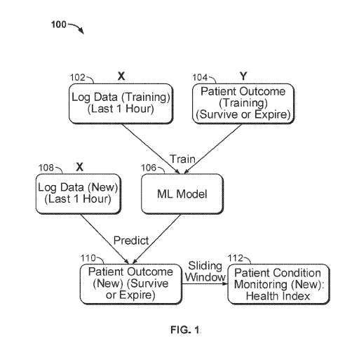
[0054] FIG. 1 shows a flowchart of a method 100 for monitoring patient
condition. The
method shown in FIG. 1 may determine a heart health index as described above.
At step 102,
a system acquires training log ("X") data for a period of time. The period of
time may be one
hour (as depicted in FIG. 1), two hours, one day or any suitable length of
time. Log data X
may correspond to the most recent period of time of a plurality of periods of
time for patient
condition monitoring. At step 104, the system acquires training patient
outcome ("Y") data.
Patient outcome data associates a patient with survival or expiration. The
patient outcome
data may be associated with the period of time of the log data, such that the
patient outcome
data is indicative of the patient's status at the end of the period of time.
Alternatively, the
patient outcome data may not be associated with the period of time of the log
data, and
instead is indicative of the patient's status at a time after the end of the
period of time. Log
data X and patient outcome data Y are obtained from a large number N of
patients, where N
is large enough to adequately train a model for accurate prediction. Log data
was measured
and/or aggregated by one or more heart pump systems. The heart pump systems
may be at
least partially inserted within the heart of the N patients. For example, a
heart pump system
may extend across the patient's aorta into his or her left ventricle. The one
or more heart
pump systems may be the same or different type of heart pump system. Heart
pump systems
compatible with the present disclosure are disclosed in U.S. Patent
Application No.
15/709,080 to Edelman et al. (U.S. Patent Publication No.: US 2018/0078159 Al,
published
March 22, 2018), the contents of which are hereby incorporated by reference in
their entirety.
Generally, any other heart pump system or system for obtaining physiological
data from a
patient may be used with the present disclosure.
[0055] At step 106, the system builds a classification model, which may be a
machine
learning model. The model is trained on the training log data X and patient
outcome data Y.
The model may be stored in a database and may include mathematical rules for
classification
of features using a learning technique. A learning technique may be logistic
regression,
decision tree, deep learning, naïve Bayesian, or any other suitable technique.
[0056] For example, logistic regression is based on an equation used to
represent the
predictive model with coefficients learned from training data. A
representation of the model
may be stored in the database as a series of the coefficients, each
corresponding to a weight
indicative of a relative importance of a particular feature and can be used to
calculate a
probability, such as the probability of survival of a patient. Probability of
expiration may be
CA 03086489 2020-06-19
WO 2019/126721
PCT/US2018/067240
calculated as (1+exp(-x))-', wherein x is equal to a*Feature_ a
+13*Feature_r3+y*Feature_y+... for any number of features and associated
coefficients.
[0057] In another example, decision tree learning uses a decision tree as a
predictive model
to go from observations about an item to conclusions about the item's target
value. Tree
depth may be a hyper-parameter in decision tree learning. A hyper-parameter is
a value that
cannot be estimated from data used in the model. Hyper-parameters are often
used to help
estimate model parameters and can be tuned for a given predictive modeling
problem.
Precision may be used as a performance metric of a predictive model. By
determining the
maximum precision of the decision tree through tuning hyper-parameters such as
tree depth,
the system can provide an optimized machine learning model (such as machine
learning
model 106), and therefore better provide a prediction (such as patient outcome
at step 110
described below). Receiver Operating Characteristic (ROC) and Area Under Curve
(AUC)
may also be used as metrics to compare prediction algorithms. In some
implementations,
steps 102, 104, 106, and any combination thereof are optional. For example,
the method may
start at step 108 described. below. In some implementations, the
classification model is
updated periodically with new patient infbrmation. In some iinplementations,
the
classification model is collated, developed by, or ran by a system separate
from the heart
pump system. For example, a third party system may collate data from multiple
different
heart pumps and build a machine learning model. That machine learning model,
may in
some examples, be used to enable steps 108 through 112.
[0058] At step 108, the system acquires new log data for a specific patient
over the time
period. The specific patient may be one of the N patients, for whom new log
data was
received, or may be a new patient not included in the N patients. At step 110,
the new log
data is input into the model trained at step 106, to predict patient outcome
for the specific
patient. Patient outcome may be a binary value representing survival or
expiration.
[0059] At step 112, the model is used, along with the new log data, to predict
the patient
condition as a health index over time. In some implementations, the health
index is displayed
for patient monitoring. For example, the health index may be displayed on the
heart pump
system or may be viewed through a computer system, mobile device, tablet, or
any other
suitable device. The health index over time is found through a sliding window
process. At a
first time of a plurality of times, the health index is calculated for the
specific patient over a
time window. The health index is then calculated for the specific patient at a
second time of
the plurality of times, still over the time window. For example, at 2:00 pm
the system may
calculate the health index of Patient W, using the past one hour of log data
(1:00 pm to 2:00
16
CA 03086489 2020-06-19
WO 2019/126721
PCT/US2018/067240
pm). At 2:15 pm the system may again calculate the health index of Patient W,
using the past
hour of log data (1:15 pm to 2:15 pm). As such, the window (the one hour time
period) is
"slid" across time in 15-minute increments to provide an updated, time-varying
health index
for the patient. The time in between calculations (15 minutes in the above
example) may be
any suitable time increment, such as one hour, half an hour, one minute, 20
seconds, etc. The
health index may be a heart health indicator, indicative of the health of the
specific patient's
heart or a probability of survival. In some implementations, the health index
is graphed over
time and displayed to a clinician, so that the clinician may see the trend of
the health index
over time.
[0060] In some implementations, the health index includes a cardiac component
and a
systemic perfusion component. The health index may be indicative of overall
patient
recovery and probability survival (i.e., patient outcome). The cardiac
component may
include unloading, contractility, or any suitable indicator of a patient's
heart performance.
The system perfusion component may include cardiac output (CO), aortic
pressure mean
(AoPm), or any suitable indicator of a patient's circulatory performance.
[0061] FIG. 2 shows a flowchart of a method 200 for predicting patient outcome
through a
method similar to that described in relation to FIG. 1. Steps 202, 204, 206,
and 208 are
identical to steps 102, 104, 106, and 108 from FIG. 1, respectively. Steps
202, 204, and 206
are optional; any combination of steps 202, 204, and 206 may be excluded from
the methods
described herein. For example, the model may already be developed or may be
imported
from an external system. At step 210, the model is used, along with the new
log data to
predict the patient condition as a health index over time. In some
implementations, the health
index is displayed for patient monitoring. The health index may be a heart
health indicator,
indicative of the health of the specific patient's heart or a probability of
survival. At step
212, the health index is used to predict patient outcome. Patient outcome may
be a binary
value representing survival or expiration. For example, the health index may
represent
patient survival probability as a value x, where x is between 0 and 1
(inclusive). The health
index may be used to determine a binary output. For example, if the health
index is greater
than 0.5 (or any other suitable threshold), the health index may indicate a
patient outcome of
survival, which corresponds to a binary value of one. This patient outcome may
be displayed
for a clinician. In FIG. 1, the system predicts patient outcome at step 110,
then uses a sliding
window to provide patient condition monitoring over time, at step 112. By
contrast, in FIG.
2, the system uses the machine learning model and log data to provide patient
health
condition monitoring over time at step 210. The system then uses the last
value calculated
17
CA 03086489 2020-06-19
WO 2019/126721
PCT/US2018/067240
during patient condition monitoring (the health index) to provide a prediction
of patient
outcome at step 212.
[0062] Data used as the log data X or the patient outcome data Y described in
relation to
FIGs. 1 and 2 may be stored in a database system. The database system may
include multiple
databases or a single database. For example, the database may include a
clinical data
database, a device registry, and AIC logs. The database system may contain
data for over
thousands of cases. Each case may correspond to a separate patient or may
correspond to an
implantation of a heart pump system. The data may represent different case
times and may
come from time periods specific to each database within the database system.
Features
described by the data stored in the database system (for example, in AIC logs)
may include
pump type, pressure signal, P-Level, flow of a heart pump system, Impella
flow, motor
current, alarms, outcome or any other suitable feature. P-level is the
performance level of the
heart pump system and relates to flow control of the system. As P-level
increases, the flow
rate and revolutions per minute associated with the heart pump system
increase. Data stored
in a database system and the data stores contained therein may be used in
training the models
described herein.
[0063] The prediction modeling systems and methods described herein follow a
data
science approach by making predictions regarding a multitude of features using
machine
learning. Data science projects start with inputting data into a system. The
data is pre-
processed and feature engineered. Preprocessing challenges may arise when
processing log
data 102 and patient outcome data 104 of FIG. 1, prior to its use in training
machine learning
model 106. Challenges may include too many missing values and non-trustable
data. Non-
trustable data may include incorrect or incomplete data. An example of non-
trustable data is
when procedure outcome is listed as "expired" but the actual outcome at the
end of intensive
care unit (ICU) support is listed as "survived," within the database system.
Incorrect data,
incomplete data and a high proportion of missing data may each affect the
performance of the
predictive model. "Bad" data may be labeled as "non-trustable" data, "too many
missing
values" data, or any other type of label that indicates the data is
untrustworthy and should be
removed from the training data set or filled in to provide a better prediction
of patient
outcome and therefore improve patient health monitoring. Other examples of pre-
processing
may include data reformatting, removing unusable features, handling outliers,
filling in
missing values, encoding categorical features, scaling and any suitable step
to resolve data
issues. Once the raw data, such as log data 102 and patient outcome data 104
of FIG. 1, has
18
CA 03086489 2020-06-19
WO 2019/126721
PCT/US2018/067240
been pre-processed, feature data may be extracted. Examples of feature data
are shown in
Table 1.
Average Std Average Std
Average Std Average
Mean Mean Placement Placement -
Cases 4 Pdiffmean Pdiffmean PdiffRange
Placement Placement Range Range
Level Level Level
Level Level Level Level.
1 74.1 32,34383 77.93333 105.7595 39.44167 44.7196 80.61667
84.08333 4.970887 44.71667 17.79896 29.90833 9,584054 109.3167
3 93.1 2.278157 55.06667 14.3479 36.01667 1.650673 84.6
4 63.93333 14.35255 68.5 53.44982 40.56667 24.161 99,7
83,65957 14.96987 147.1702 180.1325 49.39362 37.03634 149.3404
6. 95.98333 49.22313 78.15 52.57624 32.60833 22.67691 137.25
Std Average Std Average Std Average
- = Std
Cases 4 PdiffRange MeanFlow Meannow FlowRange FlowRange LVPMax LVPMax
Level Level Level Level Level Level
Level
1 87.38938 135.6833 61.04356 32.13333 27.63902 124.75 183.9011
2 26.25737 216.1667 51.2852 22.46667 .12.8614 134.5833 25.91029
3 8.410707 142.3333 3.080404 22.76667 9.733733 132.3 14.84284
4 43.12938 216.5167 40.08719 15.48333 18.91163 123.1167 67.53495
5 79.82142 198.3404 59.23458 47.93617 41.5556 225.4681 170.5296
6 65.64618 154.5167 41.42 55.18333 31.71251 181.4833 117.1217
Table 1
[0064] In some implementations, feature data is be split into training and
cross-validation
data, and used to build a machine learning technique. The machine learning
technique may
be applied to new, unclassified data to make a prediction on the new data,
such as predicting
a health status of a patient associated with the new data. The prediction,
along with the
feature data, may be further analyzed for visualization.
[0065] The systems and methods described in relation to FIGs.1 and 2 and other
processes
described herein may use a portion or all of the data held in the database
described above.
For example, a machine learning technique may be trained using only the data
stored in AIC
logs.
[0066] FIG. 3 shows a data flowchart 300 for AIC log data, such as that held
in AIC logs,
described above in relation to a database system. Long term (LT) Log Data 302
has, for
example, a placement signal. LT may correspond to one sample per minute or any
other
suitable sampling rate. Real time (RT)-Log Data 304 produces features such as
a heartbeat
19
CA 03086489 2020-06-19
WO 2019/126721
PCT/US2018/067240
rate, using information sampled at a sampling rate higher than the sampling
rate
corresponding to LT data. RT may correspond to 25 Hz (25 samples per second)
or any other
suitable sampling rate. The combination of LT Log Data and RT-Log Data is
processed as
raw and generated features that are then input to Log Data Mining 306 as X. IQ
Database
310 contains patient outcome, which is also input to Log Data Mining 306 as Y.
Log Data
Mining 306 may be used to extract relevant and/or important features for use
in training a
machine learning model, such as machine learning model 106 of FIG. 1, and may
therefore
be used to provide a more efficient patient outcome prediction.
[0067] First data related to cardiac or heart pump parameters and/or second
data related to
physiological parameters, such as the first data and second data described
above, may be used
to predict a patient outcome. In some implementations, first data and/or
second data for a
plurality of patients is used to build a predictive modeling system, such as
that described
above in relation to FIGS. 1-3. First data and/or second data may be included
in a modeling
training set or for feature extraction as described above in relation to FIG.
3. The methods
and systems described herein may test for any significant separation between
two groups of
data corresponding to patient outcome as a function of one or more patient
parameters. For
example, FIGS. 4-7 described below show two different patient parameters
graphed against
one another to determine if the parameters show a separation along patient
outcome. Only a
few examples are described herein, but such a test may be implemented for any
number of
patient parameters of first data and/or second data. Some data shown herein
show significant
separation, as shown in FIGS. 4-5. Paired parameters exhibiting significant
separation (e.g.,
as represented by boundaries 412, 422, 532) may be more predictive regarding
patient
outcome, than other parameters. Other parameters showing less significant or
no significant
separation (e.g., as exhibited in FIGS. 6-7 described below) may be less
predictive regarding
patient outcome, than other parameters.
[0068] FIGS. 4 and 5 show example feature plots used for training and
classification, for
features that lend themselves to decision boundary separation. In graphs 410,
420, and 530
unshaded dots represent survival cases, while shaded dots represent expired
cases. In each
graph the machine learning result is represented by a linear decision boundary
that is used to
separate the shaded and unshaded dots with the best trade-off, using logistic
regression. The
dots, as a whole, represent patient outcome training data, such as data Y,
described above in
relation to step 104 of FIG. 1. Their placement within graphs 410, 420, and
530 is
determined by the associated log data training, such as data X, described
above in relation to
step 102 of FIG. 1.
CA 03086489 2020-06-19
WO 2019/126721
PCT/US2018/067240
[0069] Graph 410 depicts a calculated boundary 412 for mean placement signal
(PS), which
can also be referred to as mean placement level. Placement signal may be
aortic pressure for
Impella CP/2.5 cases or differential pressure for Impella 5.0/LD cases. The x-
axis of graph
410 represents the average of the mean placement signal (PS_mean), while the y-
axis
represents the standard deviation of PS mean. For example, an unshaded dot may
represent a
patient who survived (from patient outcome training data 104). The patient is
also associated
with a set of mean placement level data (from training log data 102). The
system may
compute an average mean placement level and standard deviation of mean
placement level
for that patient and graph an associated unshaded dot, accordingly. Once the
dots have been
graphed for patients included in the training data, according to their average
mean placement
level and standard deviation of placement level, the machine learning model
(such as
machine learning model 106 of FIG. 1) calculates a linear decision boundary
412. The linear
decision boundary may be represented by a series of a coefficients tied to the
training data, as
described above. When the system receives new data relating to a new patient
(such as new
log data 108 of FIG. 1), the system may determine the average mean placement
and standard
deviation of mean placement of the new patient. Depending on where these
values "place"
the patient's dot in graph 410, a predicted patient outcome may be determined
based on the
location of the dot relative to the decision boundary 412. For example, if the
patient has an
average mean placement level of 100 and a standard deviation of mean placement
level of 30,
the predicted patient outcome would be survival, according to graph 410. This
is because the
patient's dot would fall on the right side of boundary 410, and is therefore
more strongly
associated with patients who survived (unshaded dots). Such a calculation
(where a new
patient falls in relation to a decision boundary) may constitute a patient
outcome prediction
like that described in above in relation to FIG. 1. Thus the decision boundary
may represent
a threshold for predicting patient outcome. The decision boundary may be
calculated
differently in different machine learning instances. For example, in some
instance decision
boundary 412 may be shifted to the right or the left, may have a different
slope, or may be
non-linear.
[0070] Similarly, graph 420 depicts a calculated boundary 422 for mean
differential
pressure. The x-axis of graph 420 represents the average of mean differential
pressure, while
the y-axis represents the standard deviation of mean differential pressure.
[0071] Graph 530 depicts a calculated boundary 532 for maximum left
ventricular pressure
(LVP). The x-axis of graph 530 represents the average of maximum LVP, while
the y-axis
represents the standard deviation of maximum LVP.
21
CA 03086489 2020-06-19
WO 2019/126721
PCT/US2018/067240
[0072] FIGS. 6 and 7 shows two example feature plots that do not lend
themselves to
decision boundary separation. In graphs 610, 720 unshaded dots represent
survival cases,
while shaded dots represent expired cases. Without a boundary separation, the
information
distributions shown by graphs 610, 720 may be less helpful than information
distributions
such as those shown in FIGS. 4 and 5 in predicting patient outcome, because
the system is
not provided with a clear boundary line (or equation with set of coefficients)
with which to
categorize new patient data. The x-axis of graph 610 represents slope of the
linear regression
of the PS_mean over time, while the y-axis represents the coefficient of
determination (also
known as r-squared or r2) of the linear regression of PS_mean. The data
represented in graph
610 is non-separable because the shaded and unshaded dots have the same
pattern. The x-
axis of graph 720 represents Slp(PS_mean), while the y-axis represents the
coefficient of
determination of linear regression of PS_mean. The data represented by graph
720 is semi-
separable because the shaded and unshaded dots have different patterns but may
be "weak"
for separation.
[0073] FIG. 8 shows example bar graphs ranking feature importance, as an
example result
of the machine learning techniques described herein. The feature importance
may correspond
to coefficients of a logistic regression model used, for example, as the
machine learning
model 106 of FIG. 1 to predict patient outcome. A higher coefficient in the
model may
correlate to a higher importance of a feature to overall patient health.
Knowing the feature
importance may be especially helpful for clinicians when determining a method
of treatment
in response to a decline in patient heart health (as may be exhibited by
patient condition
monitoring 112 of FIG. 1). Generally, features may include aortic pressure,
differential
pressure, motor current, left ventricular pressure, end of diastolic pressure,
aortic pulse
pressure, native cardiac output, cardiac output, CPO, placement, flow, P-
level, contractility,
and relaxation. These features may be processed to determine additional
features such as
average placement, standard deviation of placement, average placement range,
standard
deviation of placement range, average differential pressure, standard
deviation of differential
pressure, average differential pressure range, standard deviation of
differential pressure
range, left ventricular pressure maximum and left ventricular pressure
minimum. Importance
of these features may be determined by ranking the features using different
calculations.
[0074] Graph 810 shows feature ranking using F-1. F-1 is a statistical term
defined as
2*precision*recall/(precision+recall). Precision equals TP/(TP+FP) and recall
equals
TP/(TP+FN), where in TP represents true positive, FP represents false positive
and FN
represents false negative. Graph 820 shows feature ranking using precision.
Graph 830
22
CA 03086489 2020-06-19
WO 2019/126721
PCT/US2018/067240
shows feature ranking using recall. In all three graphs 810, 820, 830 the most
important
feature (the feature with highest importance) is average LVP maximum level,
suggesting that
this feature is useful in understanding a person's health status, compared to
other features
shown in FIG. 8. In graphs 810 and 830, average mean placement level is ranked
as the
second most important feature. However, in graph 820 average mean placement
level is
ranked third. The differences in feature rankings between graphs 810, 820, 830
show that the
different metrics (such as precision, recall, or F-1 score) used to calculate
the feature
importance can affect the outcome of what features are deemed most important
and are given
the most weight in the model.
[0075] Displaying a visual representation of feature importance may be helpful
to
clinicians. A graphical representation may allow a clinician to more quickly
or easily
interpret feature importance, when compared to a numerical display.
Specifically, feature
importance may be represented through a bar graph as depicted in FIG. 8 or
through a spider
plot as depicted in FIG. 9. In some implementations, a visual representation
shows the
patient's health condition and/or feature importance at a single point in time
or an average
over multiple points in time. In some implementations, the visual
representation is updated
periodically, at regular intervals, or in real time, such that the visual
representation appears to
a viewer as a video stream.
[0076] FIG. 9 shows an example spider plot 900 showing relative feature rating
for a
patient. The heart function index 902 of the patient is 0.58 in this case, and
is an example of
a heart health indicator, as described above. The CPO 904 associated with the
patient is 0.75.
CPO is a function of mean arterial pressure (MAP) and CO. CPO may be used as a
predictor
for patient outcome and may be a component of a heart health indicator. FIG. 9
shows
patient features and ratings at a single point where the CPO was 0.75 and the
heart function
index was 0.58. These values could be updated overtime. In one example, CPO
may be a
time-varying feature used in calculating the likelihood of patient survival.
[0077] Spider plot 900 visually displays the relative effect of five features
on the patient's
health. Each feature is given a rating, representing the status of the feature
for the patient on
a scale of one to five. In some implementations, the rating is on another
scale, such as zero to
one, one to ten, one to fifty, one to one hundred, one to one thousand, or any
other suitable
scale. A left ventricular (LV) contractility rating of 1 indicates a dP/dt
(which may be a
ventricular contractility assessment) max greater than 200 mmHg/sec, a rating
of two
indicates greater than 400 mmHg/sec, a rating of three indicates greater than
600 mmHg/sec,
a rating of four indicates greater than 600 mmHg/sec, and a rating of five
indicates greater
23
CA 03086489 2020-06-19
WO 2019/126721
PCT/US2018/067240
than 1000 mmHg/sec. A LVEDP rating of one indicates a deviation by 20 mmHg, a
rating
of two indicates a deviation of 15 mmHg, a rating of three indicates a
deviation of 10 mmHg,
a rating of four indicates a deviation by 5 mmHg, and a rating of five
indicates LVEDP in the
target range of 10-15 mmHg, where deviation is measured as the deviation from
this target
range. An LV relaxation rating of 1 indicates a dP/dt max less than 1000
mmHg/sec, a rating
of two indicates less than 800 mmHg/sec, a rating of three indicates less than
600 mmHg/sec,
a rating of four indicates less than 400 mmHg/sec, and a rating of five
indicates less than 200
mmHg/sec. An AoPm rating of one indicates 60 mmHg, a rating of two indicates
70 mmHg,
a rating of three indicates 80 mmHg, a rating of four indicates 90 mmHg, and a
rating of five
indicates 100 mmHg. A CO rating of one indicates a CO of 2 L/min, a rating of
two
indicates 3 L/min, a rating of three indicates 4 L/min, a rating of four
indicates 5 L/min, and a
rating of five indicates 6 L/min, where the measurement of CO is a function of
heart beat and
stroke volume. For example, LV relaxation 906 is five, LVEDP 908 is five, LV
Contractility
910 is three, CO 912 is three, and AoPm 914 is two. In this instance, AoPm is
low relative to
the other features and therefore the AoPm of the patient is worse relative to
the other features
of the patient. Displaying feature data in this manner, and on a uniform
rating scale across
features, allows a clinician to quickly view the patient data and perceive
which features may
need to be addressed to improve the overall health of the patient. In this
instance, a clinician
may look at spider plot 904 and decide to first address the patient's AoPm.
After addressing
the patient's AoPm through clinical means, a clinician may then observe,
through patient
condition monitoring (step 112 of FIG. 1) and on spider plot 904, updated
patient heart health
status in time and may track progress of the patient.
[0078] The features displayed in spider plot 904 may be weighted due to their
relative
feature importance. For example, CO may have a weighting of 0.4, LV
contractility may
have a weighting of 0.2, LVEDP may have a weighting of 0.3, AoPm may have a
rating of
0.2 and LV relaxation may have a weighting of 0.1. In this example, though
AoPm may still
have the lowest un-weighted rating, CO may have the lowest weighted rating,
because of its
relative importance and low rating. In another example, the features may be
weighted
equally.
[0079] FIG. 10 show an example of features of a specific patient, Patient X.
Graph 1010
shows a decision boundary 1012. As described above, an unshaded dot represents
survival of
a patient, while a shaded dot represents expiration of a patient. Dot 1014
represents Patient
X, who survived. Accordingly, dot 1014 is located to the right of decision
boundary 1012, as
described above. Decision boundary 1012 may represent a line between when a
patient is
24
CA 03086489 2020-06-19
WO 2019/126721
PCT/US2018/067240
more likely to survive or expire. For example, patients to the right of
boundary 1012 may be
more likely to survive while patients to the left of boundary 1012 may be more
likely to
expire. The x-axis of graph 1010 represents the average of mean placement
signal (PS),
while the y-axis represents the standard deviation of mean PS. FIG. 10 shows
one example a
user interface for the clinician when the clinician interprets the patient's
heart health by
investigating placement signal, motor current, P-level, and likelihood of
survival.
Specifically, graph 1010 allows the clinician to see a graphical
representation of the patient's
likelihood of survival in relation to a boundary between the standard
deviation and average of
placement signal. For example, graph 1010 allows a clinician to visualize a
distance between
the boundary 1012 and data representative of the patient 1014. That distance
from a
boundary or separation line may show a clinician how likely a patient is to
survive. For
example, a patient far to the right of decision boundary 1012 (e.g., a patient
with high average
placement signal) may be more likely to survive than a patient closer to the
decision
boundary (e.g, a patient with lower average placement signal).
[0080] Graph 1020 shows placement signal 1022. The y-axis of graph 1020
represents
pressure in mmHg. Graph 1030 shows motor current signal 1032. The y-axis of
graph 1030
represents motor current in mA. Graph 1040 shows P-level 1142. The y-axis of
graph 1040
represents P-level. The x-axes of graphs 1020, 1030, 1040 represent time.
Graphs 1020,
1030, 1040 are shown for the same time period, at the same time scale, for the
same patient,
Patient X, represented by dot 1014. Placement signal 1022, motor current
signal 1032, and
P-level 1042 may be indicative of first data related to time-varying
parameters of the heart
pump system, as described above. Placement signal 1022, motor current signal
1032, and P-
level 1042 may be features of a plurality of features used to determine a
heart health index for
a patient. In some aspects, the heart health index may be a probability of
survival of the
patient, which may be used to predict a patient outcome. In this case, the
patient outcome
(represented by for 1014) is survival. As shown in graph 1040, P-level is
gradually decreased
overtime. In one example, a clinician may view the Patient X's likelihood of
survival to
determine when and by how much to change the P-level. In the example shown in
FIG. 10,
the P-level is stepped down incrementally, thereby decreasing the speed of the
pump.
[0081] FIG. 11 shows another example of a specific patient, Patient Y. Graph
1110 shows
a decision boundary 1112. As described above, an unshaded dot represents
survival of a
patient, while a shaded dot represents expiration of a patient. Dot 1114
represents Patient Y,
who expired. Dot 1114 is located across boundary line 1112 from the majority
of the
CA 03086489 2020-06-19
WO 2019/126721
PCT/US2018/067240
unshaded "survival" dots. The x-axis of graph 1110 represents the average of
mean PS,
while the y-axis represents the standard deviation of mean PS.
[0082] Graph 1120 shows placement signal 1122. The y-axis of graph 1120
represents
pressure in mmHg. Graph 1130 shows motor current signal 1132. The y-axis of
graph 1130
represents motor current in mA. Graph 1140 shows P-level 1142. The y-axis of
graph 1140
represents P-level. The x-axes of graphs 1120, 1130, 1140 represent time.
Graphs 1120,
1130, 1140 are shown for the same time period, at the same time scale, for the
same patient,
Patient Y, represented by dot 1122. Placement signal 1122, motor current
signal 1132, and
P-level 1142 may be indicative of first data related to time-varying
parameters of the heart
pump system, as described above. Placement signal 1122, motor current signal
1132, and P-
level 1142 may be features of a plurality of features used to determine a
heart health index for
a patient. In some aspects, the heart health index may be a probability of
survival of the
patient, which may be used to predict a patient outcome. In this case, the
patient outcome
(represented by dot 1114) is expiration. Graph 1140 shows the variation of
target, minimum,
and maximum P-level over time. In some implementations, a clinician varies
target P-level
to increase or decrease operation of the pump to treat the patient. For
example, the clinician
may increase or decrease target P-level if the patient's probability of
survival decreases. As
one example, graph 1140 shows the target P-levels the heart pump system was
set to to treat
the patient.
[0083] The differences between FIG. 10 and FIG. 11 show how measured
characteristics
representative of a patient, such as placement signal, motor current, and P-
level may correlate
to a patient's survival for expiration. For example, the Patient X
(represented in FIG. 10)
survived, while Patient Y (represented in FIG. 11) expired. The systems and
methods
described herein predicted this outcome based on the standard deviation of
PS_mean and the
average PS_mean (new log data 108 of FIG. 1) combined with the boundary lines
1412, 1112
(machine learning model 106 of FIG. 1) which were calculated via training data
(log data 102
and patient outcome 104 of FIG. 1).
[0084] FIG. 12 shows characteristics relating to a patient over time through a
set 1200 of
four graphs. Three graphs 1210, 1220, 1230 show measured characteristics
relating to the
patient over the same time frame. Graph 1210 shows pump pressure maximum 1212,
pump
pressure mean 1214, pump pressure minimum 1216, differential pressure maximum
1219,
and differential pressure minimum 1218. The y-axis of graph 1210 represents
millimeters of
mercury (mmHg) while the x-axis represents time. Graph 1220 shows motor
current
maximum 1222, mean 1224, and minimum 1226 for a heart pump system placed in
the
26
CA 03086489 2020-06-19
WO 2019/126721
PCT/US2018/067240
patient. The y-axis of graph 1220 represents milliAmps (mA), while the x-axis
represents
time at the same scale and over the same time period as the x-axis of graph
1210. Graph
1230 shows motor speed (MS) mean 1232. The y-axis of graph 1230 represents
rotations per
minute (rpm), while the x-axis represents time at the same scale and over the
same time
period as the x-axes of graphs 1210 and 1220. Graph 1240 shows a calculated
measure of the
patient's heart health, represented as probability of survival 1242. The y-
axis of graph 1230
represents the percentage probability of survival of the patient (defined as
health status),
while the x-axis represents the same time period as described above in
relation to graphs
1210, 1220, 1230.
[0085] Pump pressure, differential pressure, motor current, and motor speed
may be
indicative of first data related to time-varying parameters of the heart pump
system, as
described above. Pump pressure maximum 1212, pump pressure mean 1214, pump
pressure
minimum 1216, differential pressure maximum 1219, differential pressure
minimum 1218,
motor current maximum 1222, motor current mean 1224, motor current minimum
1226, and
motor speed mean 1232 may be features of a plurality of features used to
determine a heart
health index for a patient. In some aspects, the heart health index may be the
probability of
survival 1242 of the patient, which may be used to predict a patient outcome.
The patient
outcome prediction may change over time.
[0086] Probability of survival 1242 may be calculated via the methods and
systems
described above. The values shown in graphs 1210, 1220, 1230 may be obtained
from a
heart pump system. Instead of using only the last hour to predict the survival
probability (H-
index), the probability of survival may be calculated on sliding windows from
the start to the
end of the case of the patient. Such a process allows the system to monitor
the health status
of the patient. Probability of survival 1242 is determined at least in part,
in this instance, by
the pump pressure, motor current, and motor speed. For example, pump pressure,
motor
current, and motor speed all dip in value just after time marker 1000. There
is a
corresponding dip in probability of survival 1242 at the same time. Such a dip
may be
indicative of a decline in heart health of the patient. By predicting a
decline in heart health,
the system may alert a clinician to a patient health problem before it may be
ordinarily
determined by the clinician, thereby providing the clinician with more time to
treat the
patient.
[0087] Results of the predictive modeling system are shown in Table 1. The
model was
tested on 13 shock cases. The shock case data is, in this instance, provided
by Henry Ford
Hospital as a "third-party" test dataset. Data for the 13 cases is shown in
Table 2.
27
CA 03086489 2020-06-19
WO 2019/126721
PCT/US2018/067240
Case Real Predicted Survival
Comments
Outcome Outcome Probability
1 Expired. Expired 0.05 Expired in procedure
Expired. Survived I Survived procedure but expired later
Survived Expired 0,41 Survived, mean pressure- is low
4 Survived Survived 0.96
Survived Survived 0.9
6 Survived Survived 0.86
7 Survived Survived 0.83
8 Survived Survived 0,87
9 Survived Survived 0,86
Survived Survived 0,62
11 Survived Survived 0.84
12 Survived Survived 0.59
Ecmo case, we thought patient did not make
13 Survived Expired 0.42
if from looking at logs
Table 2
Another independent test data set (a subset of the data held in the database
system described
above) was tested. This testing resulted in an accuracy of 81.4%, with N (the
number of
patients' data used for testing) equal to 80, as shown in Table 3.
N =80 Random Model
Accuracy 55.8% 81.4%
Precision 33.0% 79.1%
Sensitivity 33.0% 59.8%
Table 3
[0088] FIG. 13 show features over time for an example case through a set of
graphs 2000.
Three graphs 1310, 1320, 1330 show characteristics relating to a patient over
time.
Placement signal graph 1310 has a y-axis showing pressure in millimeters of
mercury
(mmHg) and an x-axis showing time. Flow graph 1320 has a y-axis showing flow
in liters
per minute (L/min) and an x-axis showing time. Health index graph 1330 has a y-
axis
showing heart health index and an x-axis showing time. The time scales of
graphs 1310,
1320, 1330 are the same, and graphs 1310, 1320, 1330 are placed such that the
x-axes of the
three graphs are aligned.
[0089] Placement signal and flow may be indicative of first data related to
time-varying
parameters of the heart pump system, as described above. Placement signal
(shown in graph
28
CA 03086489 2020-06-19
WO 2019/126721
PCT/US2018/067240
1310), mean flow and target flow (shown in graph 1320) may be features of a
plurality of
features used to determine a heart health index for a patient. The index shown
in graph 1330
may be the percentage probability of survival of the patient, which may be
used to predict a
patient outcome. The patient outcome prediction may change over time.
[0090] In the example shown in FIG. 13, a patient Z was found unresponsive at
home.
Patient Z's spouse administered cardiopulmonary resuscitation until emergency
services
arrived. A heart pump system was placed in Patient Z for 34 hours of support.
The x-axis of
graphs 1310, 1320, 1330 start approximately at the time of placement of the
heart pump
system. The mean flow 1322 of the heart system was approximately 3 L/min at P-
7 with
good performance. Marker 1340 represents a first point in time, specifically
March 12, 2016
at 5:30 am. At marker 2040 Patient Z was hemodynamically stable. Marker 1350
represents
a second point in time, specifically March 12, 2016 at 5:45 pm. At marker
1350, Patient Z
turned blue. Patient's Z's oxygen saturation (02 sats) dropped, and Patient Z
went into
ventricular tachycardia or ventricular fibrillation (VT/VF). Doctors were
unable to
resuscitate Patient Z.
[0091] The time between markers 1340 and 1350 shows significant disruptions to
the mean
flow 1322 of the heart system and placement signal 1312. As can be seen in
graph 1330, the
significant disruptions to placement signal 1312 and mean flow 1322 results in
a dramatic
change in Patient Z's heart health index 1332 between markers 1340 and 1350. A
clinician
could view the heart health index and determine the patient is at risk. Prior
to marker 1340,
graphs 1310 and 1320 are relatively steady (when compared to the high
variation shown
between markers 1340 and 1350). Graph 1330, however, shows a gradual but
steady decline
in patient health prior to marker 1340. A clinician could view the decline of
the heart health
index and determine the patient's health is deteriorating. By viewing the
decline of the heart
health index, a clinician could have intervened before the time represented by
marker 1340
(i.e., before the patient's flow and placement signal showed significant
disruption). In some
cases, early intervention is highly beneficial to patient health and is a
determining factor in
patient survival. In some examples, if the heart health index is declining
(e.g., as shown in
graph 1330 prior to marker 1340), a clinician may be alerted to the patient's
decline in health
so that the clinician may intervene in patient care. The heart health index
graph 1330 may
also be used in post-case analysis after a patient has expired.
[0092] FIG. 14 shows a flowchart of determining a probability of survival of a
patient. At
step 1400, an intravascular heart pump system is inserted into vasculature of
the patient. The
heart pump system includes a cannula, a pump inlet, a pump outlet and a rotor.
In some
29
CA 03086489 2020-06-19
WO 2019/126721
PCT/US2018/067240
implementations, the heart pump system is a left ventricular assist device
(LVAD). In some
implementations, the heart pump system is a right ventricular assist device
(RVAD). In some
implementations, the cannula, pump inlet, pump outlet, and rotor are optional.
At step 1402,
the heart pump system is positioned within the patient such that the cannula
extends across an
aortic valve of the patient, the pump inlet is located within a left ventricle
of the patient, and
the pump outlet is located within an aorta of the patient. In some
implementations, step 1402
is optional and the heart pump system is simply positioned partially within
the patient. For
example, the heart pump system may be inserted via a catheterization through
the femoral
artery, into the ascending aorta, across the aortic valve and into the left
ventricle or through
the femoral vein and into the right atrium.
[0093] At step 1403, first data is acquired. The first data relates to time-
varying parameters
of the heart pump system. The first data may represent continuous or near-
continuous
measurements acquired via the heart pump system, or represent known quantities
such as
inputs to the heart pump system. The first data relates to operation of or
factors measured by
the heart pump system, i.e., without the heart pump system the first data
would not be known.
The first data may include data indicative of heart rate, pump pressure,
differential pressure,
motor current, P-level, and/or motor speed. From these measurements, important
information
about heart function, and in some cases information about the cardiac assist
device
performance, including the occurrence of suction events, can be determined.
This information
about heart function can be used to predict a probability of patient survival,
as described
below in relation to step 1408.
[0094] In some implementations, one or sensors on the heart pump system
acquire the first
data. In some implementations, the first data is acquired through external
systems. In some
implementations, one or sensors on the heart pump system acquire the first
data. The one or
more sensors on the heart pump system may be positioned within the patient's
heart, outside
the patient's heart, or a combination of both, during operation of the heart
pump system. For
example, sensors on the heart pump system may measure pressure within the
patient's
vasculature. The measured pressure may be used in the calculation of
additional parameters,
such as cardiac power output, as described above.
[0095] At step 1404, a plurality of features are extracted from the first
data. Extracting the
features may include processing the first data at the heart pump system or at
an external
device. The plurality of features may include left ventricular end diastolic
pressure
(LVEDP), stroke volume, ejection fraction, chamber distention, chamber
hypertrophy,
chamber pressure, stroke work, preload state, afterload state, heart rate,
heart recovery, aortic
CA 03086489 2020-06-19
WO 2019/126721
PCT/US2018/067240
pressure, differential pressure, motor current, motor speed, pump pressure,
left ventricular
pressure, end of diastolic pressure, aortic pulse pressure, native cardiac
output, cardiac
output, CPO, placement, mean flow, target flow, P-level, contractility,
relaxation, a
placement signal, average placement, standard deviation of placement, average
placement
range, standard deviation of placement range, average differential pressure,
standard
deviation of differential pressure, average differential pressure range,
standard deviation of
differential pressure range, left ventricular pressure maximum, left
ventricular pressure
minimum, pump pressure maximum, pump pressure mean, pump pressure minimum,
differential pressure maximum, differential pressure minimum, motor current
maximum,
motor current minimum, motor current mean, motor speed mean, any other
suitable feature,
and any combination thereof
[0096] In some implementations, the first data are acquired during a first
time period during
which the heart pump system is in operation, such as a second, a minute, five
minutes, ten
minutes, an hour, a few hours, a day, a few days, a week, a month, or any
suitable time frame.
The average, mean, and minimum values of the features described above may be
the average,
mean, or minimum value of a feature during the first time period.
[0097] At step 1408, a probability of survival of the patient is determined.
Probability of
survival is a value that is indicative of a likelihood of patient survival or
expiration. In some
implementations, the probability of survival is a numerical value, e.g.,
between 0 and 1. In
some implementations, if the probability is greater than or equal to a
threshold (e.g., 0.5) the
probability of survival indicates survival (e.g., the patient has a greater
than 50% chance of
living given his or her heart health). The probability of survival is based on
the plurality of
features extracted in step 1404, described above, and is determined using a
prediction model.
In some implementations, the prediction model is a machine-learning model. For
example,
the prediction model may be one of a logistic regression technique, a deep
learning technique,
a decision tree, a random forest technique, a naïve Bayes technique, a support
vector
machines technique, or any other suitable model.
[0098] At step 1410, the heart pump system is operated to treat the patient.
In some
implementations step 1410 is optional. In some implementations, the heart pump
system may
operate to provide a constant or near constant level of support to the
patient. In some
implementations, the pump operation is altered based on the prediction value
of patient
outcome. In particular, altering the pump operation may include adjusting the
operating
parameters of the heart pump system to provide a level of support different
than that provided
during the time period in which the first data was acquired. In one example,
adjusting the
31
CA 03086489 2020-06-19
WO 2019/126721
PCT/US2018/067240
operating parameters of the heart pump system includes adjusting pump speed
(such as by
increasing or decreasing, for example) based on a change in cardiac power
output, lactate
concentration, or both. It may be desirable to increase pump speed when one
feature value is
below a first threshold, and when a second feature value is above a second
threshold, or both,
as described below in relation to FIG. 15.
[0099] FIG. 15 shows a flowchart of determining a prediction value of patient
outcome
based on CPO and lactate concentration. Steps 1500 and 1502 are the same as
steps 1400 and
1402 described above. At step 1504, the heart pump system is operated during a
first time
period to provide a first level of cardiac support for the patient. Examples
of providing a
level of cardiac support include operating the pump at a P-level or motor
speed, providing
current to the pump motor, turning the pump on, inducing flow through the pump
or the
patient's heart, or any other suitable method of support. The level at which
to operate the
heart pump system may be provided by a controller, for example through a user
instruction
entered via a user interface.
[0100] At step 1506, at least one CPO value is obtained. The at least one CPO
value is
derived from measurements provided by the heart pump system. Optionally, the
at least one
CPO value is representative of CPO at at least one time point within the first
time period
described above in relation to step 1504. In some implementations, CPO is
updated regularly
at fixed time intervals following the first time period. For example, the
first time interval
may be 0.01 second, 0.1 second, 0.5 second, 1 second, 5 seconds 10 seconds, 1
minute, 10
minutes, 15 minutes, 30 minutes, 1 hour, or any suitable time interval. At
step 1506, at least
one lactate concentration value is also obtained. The at least one lactate
concentration value
may be measured from the patient. For example, the lactate concentration value
may be
manually input into the heart pump system or may be retrieved from an external
database.
[0101] At step 1508, a prediction value of patient outcome is determined. The
prediction
value is based at least in part on the at least one cardiac power output value
and the at least
one lactate concentration value acquired in step 1506. It may be desirable to
increase pump
speed when the at least one CPO value is below a first threshold, when the at
least one lactate
concentration value is above a second threshold, or both. For example, the
first threshold
may be a value such as 0.3, 0.4, 0.5, 0.6, 0.7, 0.8, 0.9, 1.0 W and the second
threshold may be
a value such as 1, 2, 3, 4, 5, 6, 7 mmol/L. A low CPO value and a high lactate
value may
indicate the patient has a relatively low probability of survival. Because the
patient is not
doing well, the clinician may attempt to increase the level of cardiac support
provided by the
pump, by increasing the pump speed, for example. It may also be desirable to
decrease or not
32
CA 03086489 2020-06-19
WO 2019/126721
PCT/US2018/067240
change pump speed when the at least one CPO value is above the first
threshold, when the at
least one lactate concentration value is below the second threshold, or both.
A high CPO
value and a low lactate value may indicate the patient has a relatively high
probability of
survival. Because the patient is doing well, the clinician may decide to not
change the
parameters of the pump's operation. Alternatively, the clinician may attempt
to reduce the
level of cardiac support provided by the pump, or turn off the pump
completely. Step 1510 is
the same as step 1410 described above in relation to FIG. 14.
[0102] The foregoing is merely illustrative of the principles of the
disclosure, and the
apparatuses can be practiced by other than the described embodiments, which
are presented
for purposes of illustration and not of limitation. It is to be understood
that the apparatuses
disclosed herein, while shown for use in percutaneous insertion of heart
pumps, may be
applied to apparatuses in other applications requiring hemostasis.
[0103] Variations and modifications will occur to those of skill in the art
after reviewing
this disclosure. The disclosed features may be implemented, in any combination
and
subcombination (including multiple dependent combinations and
subcombinations), with one
or more other features described herein. The various features described or
illustrated above,
including any components thereof, may be combined or integrated in other
systems.
Moreover, certain features may be omitted or not implemented.
[0104] The systems and methods described may be implemented locally on a heart
pump
system or a controller of a heart pump system, such as the AIC. The heart pump
system may
include a data processing apparatus. The systems and methods described herein
may be
implemented remotely on a separate data processing apparatus. The separate
data processing
apparatus may be connected directly or indirectly to the heart pump system
through cloud
applications. The heart pump system may communicate with the separate data
processing
apparatus in real-time (or near real-time).
[0105] In general, embodiments of the subject matter and the functional
operations
described in this specification can be implemented in digital electronic
circuitry, or in
computer software, firmware, or hardware, including the structures disclosed
in this
specification and their structural equivalents, or in combinations of one or
more of them.
Embodiments of the subject matter described in this specification can be
implemented as one
or more computer program products, i.e., one or more modules of computer
program
instructions encoded on a computer readable medium for execution by, or to
control the
operation of, data processing apparatus. The computer readable medium can be a
machine-
readable storage device, a machine-readable storage substrate, a memory
device, a
33
CA 03086489 2020-06-19
WO 2019/126721
PCT/US2018/067240
composition of matter affecting a machine-readable propagated signal, or a
combination of
one or more of them. The term "data processing apparatus" encompasses all
apparatus,
devices, and machines for processing data, including by way of example a
programmable
processor, a computer, or multiple processors or computers. The apparatus can
include, in
addition to hardware, code that creates an execution environment for the
computer program
in question, e.g., code that constitutes processor firmware, a protocol stack,
a database
management system, an operating system, or a combination of one or more of
them. A
propagated signal is an artificially generated signal, e.g., a machine-
generated electrical,
optical, or electromagnetic signal that is generated to encode information for
transmission to
suitable receiver apparatus.
[0106] A computer program (also known as a program, software, software
application,
script, or code) can be written in any form of programming language, including
compiled or
interpreted languages, and it can be deployed in any form, including as a
stand-alone program
or as a module, component, subroutine, or other unit suitable for use in a
computing
environment. A computer program may correspond to a file in a file system. A
program can
be stored in a portion of a file that holds other programs or data (e.g., one
or more scripts
stored in a markup language document), in a single file dedicated to the
program in question,
or in multiple coordinated files (e.g., files that store one or more modules,
sub programs, or
portions of code). A computer program can be deployed to be executed on one
computer or
on multiple computers that are located at one site or distributed across
multiple sites and
interconnected by a communication network.
[0107] The processes and logic flows described in this specification can be
performed by
one or more programmable processors executing one or more computer programs to
perform
functions by operating on input data and generating output. The processes and
logic flows
can also be performed by, and apparatus can also be implemented as, special
purpose logic
circuitry, e.g., an FPGA (field programmable gate array) or an ASIC
(application specific
integrated circuit).
[0108] Processors suitable for the execution of a computer program include, by
way of
example, both general and special purpose microprocessors, and any one or more
processors
of any kind of digital computer. Generally, a processor will receive
instructions and data
from a read-only memory or a random access memory or both. The essential
elements of a
computer are a processor for performing instructions and one or more memory
devices for
storing instructions and data. Generally, a computer will also include, or be
operatively
coupled to receive data from or transfer data to, or both, one or more mass
storage devices for
34
CA 03086489 2020-06-19
WO 2019/126721
PCT/US2018/067240
storing data, e.g., magnetic, magneto optical disks, or optical disks.
However, a computer
need not have such devices.
[0109] Examples of changes, substitutions, and alterations are ascertainable
by one skilled
in the art and could be made without departing from the scope of the
information disclosed
herein. All references cited herein are incorporated by reference in their
entirety and made
part of this application.
CA 03086489 2020-06-19
WO 2019/126721
PCT/US2018/067240
Example embodiments:
1. A method for predicting a patient outcome, the method comprising:
acquiring, during a first time period and from a heart pump system, first data
related to time-varying parameters of the heart pump system;
extracting a plurality of features from the first data;
determining, using a prediction model and based on the plurality of features,
a
heart health index indicative of the health of the patient's heart; and
predicting, based on the heart health index, a patient outcome.
2. The method of embodiment 1, wherein the heart health index is further
indicative of a
likelihood of patient recovery.
3. The method of embodiment 1 or 2, wherein the heart health index is
representative of
a cardiac component and a systemic perfusion component.
4. The method of any one of embodiments 1-3, wherein the heart pump system
is at
least partially inserted within the patient's heart.
5. The method of any one of embodiments 1-4, further comprising:
acquiring second data related to physiological parameters of a patient; and
extracting a second plurality of features from the second data,
wherein determining the heart health index is further based on the second
plurality of features.
6. The method of embodiment 5, wherein the second plurality of features
includes at
least one of: age, gender, body surface area (BSA), urine output, creatinine
level,
potential of Hydrogen (pH), oxygen concentration, carbon dioxide
concentration, and
lactate concentration.
7. The method of any one of embodiments 1-6, further comprising displaying
the heart
health index.
8. The method of any one of embodiments 1-7, further comprising:
36
CA 03086489 2020-06-19
WO 2019/126721
PCT/US2018/067240
acquiring a plurality of heart health indices including the heart health
index,
each heart health index corresponding to a time period of a plurality of time
periods;
and
determining, based on the plurality of heart health indices, a change in
patient
health.
9. The method of embodiment 8, further comprising displaying the plurality
of heart
health indices over the plurality of time periods.
10. The method of any one of embodiments 1-9, wherein the plurality of
features includes
at least one of: aortic pressure, differential pressure, motor current, motor
speed,
pump pressure, left ventricular pressure, end of diastolic pressure, aortic
pulse
pressure, native cardiac output, cardiac output, cardiac power output,
placement, flow,
P-level, contractility, relaxation, average placement, standard deviation of
placement,
average placement range, standard deviation of placement range, average
differential
pressure, standard deviation of differential pressure, average differential
pressure
range, standard deviation of differential pressure range, left ventricular
pressure
maximum, and left ventricular pressure minimum.
11. The method of any one of embodiments 1-10, wherein the prediction model is
a
machine learning model.
12. The method of embodiment 11, wherein the machine learning model is one of:
a
logistic regression technique, a deep learning technique, a decision tree, a
random
forest technique, a naïve Bayes technique, and a support vector machines
technique.
13. The method of any one of embodiments 1-12, further comprising:
displaying an indicator of a relative importance of a first feature of the
plurality of features compared to a second feature of the plurality of
features.
14. The method of any one of embodiments 1-13, wherein determining the heart
health
index comprises:
acquiring, from a database, a training dataset comprising a plurality of data
points relating to time-varying parameters of a heart pump system;
37
CA 03086489 2020-06-19
WO 2019/126721
PCT/US2018/067240
pre-processing the dataset to determine a third plurality of features
corresponding to the plurality of data points;
processing the third plurality of features to determine a pattern, wherein the
pattern comprises a weight of each feature of a subset of the third plurality
of features;
acquiring patient data;
calculating, based on the patient data and the pattern, the heart health index
of
a patient.
15. The method of any one of embodiments 1-14, wherein the first data
comprises data
indicative of placement signal, motor current, and P-level over time.
16. The method of any one of embodiments 1-15, wherein the plurality of
features
includes: placement signal, motor current, P-level, and the standard deviation
of the
placement signal.
17. The method of any one of embodiments 1-16, wherein the first data
comprises data
indicative of pump pressure, differential pressure, motor current, and motor
speed
over time.
18. The method of any one of embodiments 1-17, wherein the plurality of
features
includes: pump pressure maximum, pump pressure mean, pump pressure minimum,
differential pressure maximum, differential pressure minimum, motor current
maximum, motor current minimum, motor current mean, and motor speed mean.
19. The method of any one of embodiments 1-18, wherein the first data
comprises data
indicative of placement signal and flow over time.
20. The method of any one of embodiments 1-19, wherein the plurality of
features
includes: placement signal, mean flow, and target flow.
21. The method of any one of embodiments 1-20, wherein the heart health index
is a
probability of survival of the patient.
22. The method of any one of embodiments 1-21, wherein the patient outcome is
expiration of the patient.
38
CA 03086489 2020-06-19
WO 2019/126721
PCT/US2018/067240
23. The method of any one of embodiments 1-21, wherein the patient outcome is
survival
of the patient.
24. A heart pump system comprising:
a catheter;
a motor;
a rotor operatively coupled to the motor;
a pump housing at least partially surrounding the rotor so that that actuating
the motor drives the rotor and pumps blood through the pump housing;
at least one sensor; and
a controller configured to:
perform the method of any of embodiments 1-23.
25. A system comprising a controller configured to perform the method of any
of
embodiments 1-23.
39