Note: Descriptions are shown in the official language in which they were submitted.
-1-
BIOABSORBABLE FLOW DIVERTING SCAFFOLD
BACKGROUND OF THE INVENTION
1. Field of Invention
This disclosure relates to scaffolds made of a braid of bioabsorbable
polymeric
fibers for implantation within a lumen of a mammalian body. Particular aspects
of
this disclosure relate scaffolds made from such braids that are configured to
divert
blood flow from a pathology associated with a blood vessel.
2. Related Application
This application claims priority to United States patent application no.
62/641891.
3. Description of Related Art
There is an abundance of medical devices that are known in the art, which are
implanted into blood vessels in the body to treat various pathologies. For
example,
an aneurysm is an outward bulging, balloon-like structure caused by a
localized
weak spot on a blood vessel wall. Aneurysms have thin, weak walls and are thus
at risk of rupturing. "Flow-diverting" scaffolds have been proposed to treat
aneurysms, by which a stent is inserted to span the neck of an aneurysm in
order
to divert flow past the aneurysm and thus allow it to heal. Flow diversion
thus
removes the need to enter an aneurysm. Such flow-diverting scaffolds are
described in, for example, US 871531 and US 8267986. US 871531 and US
8267986 describe scaffolds made of braided metal wires. The PipelineTM Flex
embolization device (Medtronic), is used for endovascular treatment of large
or
giant wide-necked intracranial aneurysms. The Pipeline TM Flex device consists
of
75% cobalt chromium / 25% platinum tungsten wires.
The metal composition of the flow-diverting scaffolds known in the art
provides
disadvantages. As they are permanent and cannot be removed, they present the
Date Recue/Date Received 2020-07-17
WO 2019/173912 PCT/CA2019/050304
-2-
various drawbacks, including risk of thrombosis that requires patients to
remain
anti-platelet medications long -term, risk of hyperplasia, prevention of
vascular
lumen remodeling or expansion, and occlusion of the blood vessel. Metal
scaffolds
are also present disadvantages in the context of CT and MRI imaging post-
implantation as the signal they reflect tends to be too bright.
Accordingly, there is a need for an implantable devices that eliminate or
reduce the
negative responses of the body at the implantation site while allowing for the
prevention or treatment of a disease. Bioresorbable scaffolds have advantages
compared to the metal scaffolds, including non-permanency. However, clinical
studies showed that bioabsorbable coronary have higher risks of thrombosis
(Masayuki et al., Circulation 136, A15796¨A15796; Raber et al., ACC (Journal
Am.
Coll. Cardiol. 66, 1901-1914; Kang et al., ACC Cardiovasc. Interv. 9, 1203-
1212).
Furthermore, Waksmen et al. (Circ. Cardiovasc. Interv. 10, e004762) have
demonstrated the higher thrombogenicity of scaffolds made with the
bioabsorbable
polymer nature of PLLA.
SUMMARY OF THE INVENTION
Other aspects and features of the present invention will become apparent to
those
ordinarily skilled in the art upon review of the following description of
specific
embodiments of the invention in conjunction with the accompanying figures.
Aspects of the disclosure relate to a device comprising a resiliently
deformable
tubular body for positioning in a body lumen defined by a body wall, the
tubular
body comprising a braid of interwoven bioabsorbable polymeric fibers, wherein
the
tubular body comprises at least 38 polymeric fibers. In various embodiments,
when the device is in an expanded formation, the braid has a porosity in the
range
of about 5% to about 80%. In various embodiments, when the device is in an
expanded formation, the braid has a porosity in the range of about 60% to
about
80%
Date Recue/Date Received 2020-07-17
WO 2019/173912 PCT/CA2019/050304
-3-
Aspects of the disclosure relate to a device comprising a resiliently
deformable
tubular body for positioning in a body lumen defined by a body wall, the
tubular
body comprising a braid of interwoven bioabsorbable polymeric fibers, wherein,
when the device is in an expanded formation, the braid has a porosity in the
range
of about 60% to about 80%. In various embodiments, the tubular body comprises
at least 38 polymeric fibers.
In various embodiments of the devices described above, the braid comprises 38
to
96 bioabsorbable polymeric fibers. In various embodiments, the braid comprises
at
least 44 bioabsorbable polymeric fibers. In various embodiments, the braid
comprises at least 46 bioabsorbable polymeric fibers. In various embodiments,
the
braid comprises at least 48 bioabsorbable polymeric fibers. In various
embodiments, the braid comprises at least 72 bioabsorbable polymeric fibers.
In
various embodiments, the braid comprises 44 bioabsorbable polymeric fibers. In
various embodiments, the braid comprises 46 bioabsorbable polymeric fibers. In
various embodiments, the braid comprises 48 bioabsorbable polymeric fibers. In
various embodiments, wherein the braid comprises 72 bioabsorbable polymeric
fibers. In various embodiments, the braid comprises at least 96 bioabsorbable
polymeric fibers.
In various embodiments of the devices described above, the bioabsorbable
polymeric fibers have a diameter of at least about 30 pm. In various
embodiments,
the bioabsorbable polymeric fibers have a diameter in the range of about 30 pm
to
about 80 pm. In various embodiments, the bioabsorbable polymeric fibers have a
diameter of about 40 pm. In various embodiments, bioabsorbable polymeric
fibers
have a diameter of about 50 pm. In various embodiments, the bioabsorbable have
a diameter of about 60 pm. In various embodiments, the bioabsorbable polymeric
fibers have a diameter of about 70 pm. In various embodiments, the
bioabsorbable
polymeric fibers have a diameter of about 80 pm.
Date Recue/Date Received 2020-07-17
WO 2019/173912 PCT/CA2019/050304
-4-
In various embodiments of the devices described above, the bioabsorbable
polymeric fibers are interwoven in a 2-under-2-over-2 pattern. In various
embodiments, the bioabsorbable polymeric fibers are interwoven in a 1-overr-2-
under-2 pattern. In various embodiments, the bioabsorbable polymeric fibers
are
interwoven in 1-over-1-under-1 pattern.
In various embodiments of the devices described above, the diameter of the
tubular body is about 4 mm. In various embodiments, the bioabsorbable
polymeric
fibers are interwoven at a pitch angle of about 16 or less. In various
embodiments,
the bioabsorbable polymeric fibers are interwoven at a pitch angle of about 14
or
less.
In various embodiments of the devices described above, the diameter of the
tubular body is about 5 mm. In various embodiments, the bioabsorbable
polymeric
fibers are interwoven at a pitch angle of about 12 or less. In various
embodiments,
the bioabsorbable polymeric fibers are interwoven at a pitch angle of about 10
or
less.
In various embodiments of the devices described above, the diameter of the
tubular body is about 3 mm. In various embodiments, the bioabsorbable
polymeric
fibers are interwoven at a pitch angle of about 18 or less. In various
embodiments,
the bioabsorbable polymeric fibers are interwoven at a pitch angle of about 16
or
less.
In various embodiments of the devices described above, the the diameter of the
tubular body is about 7 mm. In various embodiments, the bioabsorbable
polymeric
fibers are interwoven at a pitch angle of about 9 or less.
Date Recue/Date Received 2020-07-17
WO 2019/173912 PCT/CA2019/050304
-5-
In various embodiments of the devices described above, when the device is in
an
expanded formation the braid has a pore density of in the range of about 10
pores/mm2 to about 32 pores/mm2.
In various embodiments of the devices described above, the tubular body
further
comprises a visualization aid. In various embodiments, the visualization aid
comprises a radio-opaque material. In various embodiments, the the radio
opaque
material comprises iodine or barium. In various embodiments, the visualization
aid
comprises at least one wire comprising a radio-opaque material, wherein each
wire
is interwoven with the plurality of bioabsorbable polymeric fibers to form
part of the
braid.
In various embodiments of the devices described above, the tubular body
comprises means for facilitating and/or maintaining radial and/or axial
expansion of
the tubular body in the body lumen. In various embodiments, the means for
facilitating and maintaining expansion of the tubular body in the body lumen
is at
least one wire, wherein each wire is interwoven with the plurality of
bioabsorbable
polymeric fibers to form part of the braid. In various embodiments, the at
least one
wire comprises a radio opaque material.
In various embodiments of the devices described above, the at least one wire
is a
resiliently deformable wire. In various embodiments, the resiliently
deformable wire
comprises a nickel-titanium alloy or a cobalt-chromium-nickel alloy. In
various
embodiments, each wire independently comprises: a nickel-titanium alloy coated
with the radio-opaque material; a drawn filled tube (DFT) comprising a nickel-
titanium alloy exterior and a core comprising the radio-opaque material; a DFT
comprising an exterior comprising the radio-opaque material and a core
comprising
a nickel-titanium alloy; a cobalt-chromium-nickel alloy coated with the radio-
opaque
material; a (DFT) comprising a cobalt-chromium-nickel alloy exterior and a
core
Date Recue/Date Received 2020-07-17
WO 2019/173912 PCT/CA2019/050304
-6-
comprising the radio-opaque material; or a DFT comprising an exterior
comprising
the radio-opaque material and a core comprising cobalt-chromium-nickel alloy.
In various embodiments of the devices described above, the radio-opaque
material
comprises iodine or barium.
In various embodiments of the devices described above, the radio-opaque
material
comprises a radio-opaque metal. In various embodiments, the radio-opaque metal
is tantalum, gold, platinum, or a combination thereof.
In various embodiments of the devices described above, the at least one wire
comprises a tantalum-coated nitinol wire.
In various embodiments of the devices described above, the at least one wire
comprises a DFT comprising a nitinol exterior and a platinum core.
In various embodiments of the devices described above, the at least one wire
comprises 2 wires, 3 wires, 4 wires, 5 wires, 6 wires, 7 wires, 8 wires, 9
wires, or
10 wires.
In various embodiments of the devices described above, the plurality of
polymeric
fibers comprise polylactides (PLA), polyglycolides (PGA), polycaprolactone
(PCL),
polylactide-co-glycolides (PLGA), polyanhydrides, polyorthoesters, poly(N-(2-
hydroxypropyl) methacrylamide), poly(I-aspartamide), DLPLA- poly(dl-lactide),
poly
(L-Lactic acid); LPLA- poly(1-lactide), PDO- poly (dioxanone), PGA-TMC- poly
(polyglycolide-co-trimethylene carbonate), PGA-LPLA- poly(1-lactide-co-
glycolide),
PGA-DLPLA- poly(dl-lactide-co-glycolide), LPLA-DLPLA- poly(l-lactide-co-dl-
lactide), PDO-PGA-TMC- poly(glycolide-co-trimethylene carbonate-co-dioxanone),
or any combination thereof. In various embodiments, the plurality of polymeric
fiber
comprise polylactides (PLA), polylactide-co-glycolides (PLGA), DLPLA- poly(d1-
lactide), poly-L-Lactic acid), LPLA- poly(1-lactide), PGA-LPLA- poly(1-lactide-
co-
Date Recue/Date Received 2020-07-17
WO 2019/173912 PCT/CA2019/050304
-7-
glycolide), PGA-DLPLA- poly(dl-lactide-co-glycolide), LPLA-DLPLA- poly(1-
lactide-
co-dl-lactide), or any combination thereof. In various embodiments, the
plurality of
polymeric fibers comprise poly-L-lactic acid (PLLA).
In various embodiments of the devices described above, the tubular body
comprises a therapeutic agent conjugated to the bioabsorbable polymeric
fibers. In
various embodiments, the bioabsorbable polymeric fibers are coated with a
therapeutic agent. In various embodiments, the therapeutic agent is an
antibiotic
agent, an antiviral agent, an analgesic, a muscle relaxant, a
chemotherapeutic agent, an intra-arterial vasodilating agent, a calcium
channel
inhibitor, a calcium channel antagonist, a calcium channel blocker, a
transient
receptor potential protein blocker, an endothelin antagonist, a blood thinning
agent,
an antiplatelet agent, or any combination thereof. In various embodiments, the
therapeutic agent is aspirin, heparin, Ticagrelor, 5-fluorouracil, melphalan,
or
clopidogrel. In various embodiments, the therapeutic agent is paclitaxel,
sirolimus,
everolim us, temozolamide, cyclophosphamide, doxorubicin,
irinotecan,
azathioprine, methotrexate, cisplatin, or vincristine.
In various embodiments of the devices described above, the lumen is the lumen
of
a blood vessel. In various embodiments, the blood vessel is an intracranial
vessel.
In various embodiments, the device is for positioning adjacent to a pathology
of the
blood vessel to divert blood flow from the pathology. In various embodiments,
the
pathology is an aneurysm, a cancer, an infection, coronary artery disease,
carotid
artery atherosclerotic disease, or intracranial atherosclerosis.
In various embodiments of the devices described above, the device is for
positioning in the lumen at a site adjacent to a pathology of or proximal to
the body
wall to supply lactic acid to the site.
Date Recue/Date Received 2020-07-17
-8-
Aspects of the disclosure relate to use of a device as defined above for
deployment within a
lumen of a body to treat a pathology of or proximal to a body wall defining
the lumen. Aspects
of the disclosure relate to use of a device as defined above for deployment
within a body
lumen to deliver a therapeutic agent to a pathology of or proximal to a body
wall defining the
lumen. Aspects of the disclosure relate to use of a device as defined above
for deployment
within a body lumen to deliver lactic acid to a site proximal to a pathology
of or proximal to a
body wall defining the lumen. In various embodiments, the body wall is the
wall of a blood
vessel. In various embodiments, the blood vessel is an intracranial blood
vessel. In various
embodiments, the pathology is an aneurysm, a cancer, an infection, coronary
artery disease,
carotid artery atherosclerotic disease, or intracranial atherosclerosis.
Aspects of the disclosure relate to a method of treating a pathology of or
proximal to a body
wall, the method comprising deploying a device as defined in above in a lumen
defined by the
body wall at a position proximal to the pathology. Aspects of the disclosure
relate to a method
of delivering lactic acid to a site proximal to a pathology of, or proximal
to, a body wall, the
method comprising deploying a device as described above within a lumen defined
by the body
wall at the site proximal to the pathology. In various embodiments, the body
wall is the wall of
a blood vessel. In various embodiments, the blood vessel is an intracranial
blood vessel. In
various embodiments, the pathology is an aneurysm, a cancer, an infection,
coronary artery
disease, carotid artery atherosclerotic disease, or intracranial
atherosclerosis.
Various aspects of the disclosure related to a device, comprising a
resiliently deformable
tubular body for positioning in a body lumen defined by a body wall, the
tubular body
comprising a braid consisting of: interwoven bioabsorbable polymeric fibers;
and one or more
wires comprising a radio-opaque material, wherein each wire is interwoven with
the
bioabsorbable polymeric fibers to form part of the braid.
BRIEF DESCRIPTION OF THE DRAWINGS
In drawings which illustrate embodiments of the invention,
Date Recue/Date Received 2020-07-17
WO 2019/173912 PCT/CA2019/050304
-9-
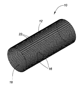
Figure 1 is an isometric view of an implantable device comprising a
braid of
interwoven bioasbsorbable polymeric fibers according to a first
embodiment;
Figure 2 is a picture of an embodiment of an implantable
endovascular device
comprising 48 interwoven poly L-lactic acid (PLLA) polymeric fibers;
Figure 3 is a picture of an embodiment of an implantable
endovascular device
comprising 48 interwoven poly L-lactic acid (PLLA) polymeric fibers
showing the resilient deformability of the device;
Figure 4 is a schematic diagram of an implantable device comprising
a braid of
interwoven fibers that illustrates pitch angle.
Figure 5 is a schematic diagram of a braiding machine useful for
manufacturing
devices of the present disclosure.
Figure 6A is an isometric view of an implantable device according to
a second
embodiment of the invention comprising a braid of interwoven
bioabsorbable polymeric fibers and radio-opaque material;
Figure 6B is a side view of the device illustrated in Figure 6A,
Figure 7A is a picture of an embodiment of an implantable
endovascular device
comprising 44 interwoven poly L-lactic acid (PLLA) polymeric fibers and
4 radio-opaque wires;
Figure 7B is a close up picture of the device of Figure 7A;
Figure 8A is a picture of an embodiment of an implantable
endovascular device
comprising 46 interwoven poly L-lactic acid (PLLA) polymeric fibers and
2 radio-opaque wires;
Figure 8B is a close up picture of the device of Figure 8A;
Figure 9A is a schematic diagram of a flow diverting application to treat
of an
aneurysm;
Figure 9B is a schematic diagram of a flow diverting application to
treat of an
aneurysm;
Figure 10 is a schematic diagram of a flow diverting application in
combination
with an aneurysm-bridging application.;
Date Recue/Date Received 2020-07-17
WO 2019/173912 PCT/CA2019/050304
-10-
Figure 11A is an early arterial phase angiogram taken before device
implantation,
showing an aneurysm created in a rabbit carotid artery with a daughter
sac at the tip of the aneurysm;
Figure 11B is an early venous phase angiogram of the same aneurysm shown in
Figure 19A (same angiographic run as above) before device
implantation, demonstrating rapid contrast washout except in the
daughter sac;
Figure 11C is an early venous phase angiogram of the same aneurysm shown in
Figures 19A and 19B after placement of the device, demonstrating
contrast stagnation in the body of the aneurysm indicative of a flow
diverting effect;
Figure 12A is an angiogram of a rabbit aorta immediately after implantation of
a
device comprising 44 bioabsorbable PLA fibers and radio-opaque
Tantalum-coated nitinol fibers;
Figure 12B is an angiogram of the rabbit aorta depicted in Figure 14A 1 month
after
implantation of the device;
Figure 13 is a scanning electron micrograph (SEM) showing persistent
patency
of a side branch of a rabbit aorta 1 month after implantation of the
device;
Figure 14 is a gross histology picture of a device comprising 44
bioabsorbable
PLA fibers and 4 radio-opaque Tantalum-coated nitinol fibers after
implantation in a rabbit aorta;
Figure 15 are scanning electron micrographs (SEM) showing a smooth
neointimal layer forming over the stent struts 1 month after
implantation of the device into the rabbit aorta;
Figure 16A is a histological cross section of a rabbit aorta showing
persistence of
polymer fibers and neointima formation over the fibers one month
after implantation of a device;
Figure 16B is a histological cross section of a rabbit aorta showing
persistence of
polymer fibers, neointima formation over the fibers, and a lack of
Date Recue/Date Received 2020-07-17
WO 2019/173912 PCT/CA2019/050304
-11-
exuberant inflammatory response two months after implantation of a
device.
Figure 17 is a picture of a device according to an embodiment
disclosed herein
consisting only of bioabsorbable PLLA polymeric fibers, illustrating its
ability to self-expand after being loaded into, then pushed out of, a
catheter with an inner diameter of 0.027".
DEFINITIONS
Definitions
"Pathology" as used herein refers to the structural and functional deviations
from
the normal that constitutes or characterizes a disease, condition, or
disorder.
"Comprising" as used herein means "including, but not limited to".
"Consisting" as used herein means "including and limited to".
"Drug" or "therapeutic agent" as used herein can refer to any of a variety of
drugs,
pharmaceutical compounds, other bioactive agent that can be used as active
agents to prevent or treat a disease.
"Bioabsorbable", "biodegradable", and "bioresorbable" are used herein
synonymously to refer to a material or structure that degrades or dissolves in
living
tissues or systems of a body over time.
"Body lumen" as used herein refers to the cavity defined by a tubular
structure of a
mammalian body including, but not limited to, a blood vessel, a ureter, a
urethra, a
bile duct.
Date Recue/Date Received 2020-07-17
WO 2019/173912 PCT/CA2019/050304
-12-
"Wall" as used herein refers to tissue that forms a tubular structure of a
mammalian
body including, but not limited to, a blood vessel wall, a ureter wall, a
urethra wall,
a bile duct wall.
"Scaffold" as used herein refers to a tubular structures that may be inserted
into a
body lumen. Scaffolds include stents that can insert into a blocked
passageways
to keep them open andrestore the flow of blood or other fluids. Scaffolds also
include devices that are not primarily intended to keep a blocked passageway
open, but rather intended to divert flow of fluids. Scaffolds may also serve
as a
support for tissue growth such as neointimal growth. Scaffolds may also serve
as a
platform for the delivery of therapeutic agents. Scaffolds may be made made of
either metal or plastic.
"Visualization aid" as used herein refers to any structure that facilitates
imaging by
x-ray fluoroscopy.
"Resiliently deformable" as used herein pertains to an object that is capable
of
autonomously returning to its original shape upon release from a bent,
stretched,
compressed, or otherwise deformed shape.
"Endovascular device" as used herein refers to a prosthesis that can be
implanted
within a body lumen or body conduit.
"Fiber" as used herein refers to a filament, thread, tendril, or strand from
which a
textile is formed.
"Polymeric fiber" as used herein refers to fibers comprising a series of
repeating
monomeric units that have been cross-linked or polymerized. In some
embodiments
disclosed herein, only one polymer is used. In another embodiment, a
combination
Date Recue/Date Received 2020-07-17
WO 2019/173912 PCT/CA2019/050304
-13-
of two or more polymers may be used. In another embodiment, polymers may be
used with radio-opaque materials. The polymers and the combinations of
polymers
can be used in varying ratios to provide different properties. Polymers that
may be
used in the present invention include, for example, stable polymers, biostable
polymers, durable polymers, inert polymers, organic polymers, organic-
inorganic
copolymers or inorganic polymers. Suitable polymers are bioabsorbable,
biocompatible, bioresorbable, resorbable, degradable, and biodegradable
polymers.
"Flow-diversion" as used herein refers to diversion of bodily fluid flow away
from a
pathology.
"Porosity" as used herein is, for a device in its fully expanded formation,
the ratio of
the free area to the total area, where the free area is equal to the total
area minus
the material surface area. In other words, the percentage of the overall
device wall
surface area that is open and fiber-free.
DETAILED DESCRIPTION
This disclosure generally relates to implantable devices, methods for
manufacture
and uses in either the prophylaxis or treatment of a pathology. Any term or
expression not expressly defined herein shall have its commonly accepted
definition understood by a person skilled in the art. To the extent that the
following
description is of a specific embodiment or a particular use of the invention,
it is
intended to be illustrative only, and not limiting of the invention, which
should be
given the broadest interpretation consistent with the description as a whole
and
with the claims.
Referring to Figures 1 and 2, a device for positioning with a body lumen to
achieve
flow diversion of a bodily fluid according to a first embodiment of the
invention is
Date Recue/Date Received 2020-07-17
WO 2019/173912 PCT/CA2019/050304
-14-
shown generally at 10. Referring to Figure 2, device 10 comprises a
resiliently
deformable tubular body 12 formed of a braid 14 of interwoven bioabsorbable
polymeric fibers 16. Referring to Figure 1, tubular body 12 defines a lumen 18
through which a bodily fluid can continue to flow when device 10 is deployed
within
a body lumen. Overlapping bioabsorbable polymeric fibers 16 define pores 22.
In the presently described embodiment, braid 14 consists of 48 bioabsorbable
polymeric fibers. However, flow diversion may be achieved with braids
consisting
of as few as 38 bioabsorbable polymeric fibers and as many as 96 bioabsorbable
polymeric fibers. In various embodiments of the presently disclosed devices
that
are useful for flow diversion, a braid may comprise 40, 42, 44, 46, 48, 50,
52, 54,
56, 58, 60, 62, 64, 66, 68, 70, 72, 74, 76, 78, 80, 82, 84, 86, 88, 90, 92, or
94
bioabsorbable polymeric fibers.
In particular embodiments of the presently
disclosed devices that are useful for flow diversion, a braid may consist of
40, 42,
44, 46, 48, 50, 52, 54, 56, 58, 60, 62, 64, 66, 68, 70, 72, 74, 76, 78, 80,
82, 84, 86,
88, 90, 92, or 94 bioabsorbable polymeric fibers.
For applications where flow diversion is not necessary or desired, the braid
of the
presently disclosed invention could include as few as 20 bioabsorbable
polymeric
fibers, as few as 18 bioabsorbable polymeric fibers, as few as 16
bioabsorbable
polymeric fibers, as few as 14 bioabsorbable polymeric fibers, or as few as 12
bioabsorbable polymeric fibers.
In the presently described embodiment, braid 14 consists of bioabsorbable
polymeric fibers 16 having a diameter of 50 pm. Bioabsorbable polymeric fibers
useful for the production of devices useful for flow diversion as disclosed
herein will
have a diameter of at least about 30 pm, and will generally have a diameter in
the
range of about 30 pm to about 80 pm. In various embodiments of the presently
disclosed devices that are useful for flow diversion, the bioabsorbable
polymeric
fibers will have a diameter of about 30 pm, about 40 pm, about 50 pm, about 60
Date Recue/Date Received 2020-07-17
WO 2019/173912 PCT/CA2019/050304
-15-
pm, about 70 pm, or about 80 pm.
The skilled person will understand that
bioabsorbable polymeric fibers with any diameter within this range may be
useful in
the production of a flow-diverting device.
For a flow diverting device, it is desirable for the tubular body to have a
high
flexibility so that it can be delivered through a microcatheter and, in
various
applications, through tortuous blood vessels and into the intracranial
circulation.
Accordingly, the upper limit of the diameter of the bioabsorbable polymeric
fibers
will be dictated by the desired flexibility of the tubular body as well as the
diameter
of the lumen into which the device is to be deployed.
Figure 3 is a picture demonstrating the flexibility and resilient
deformability of the
device consisting of 48 poly-L-lactic acid (PLLA) bioabsorbable fibers.
Porosity
The braided nature of the device is essential to flow diversion applications.
The
braid allows for the manufacture of a tubular body with a sufficiently high
material
surface area/ sufficiently low porosity to prevent significant lateral flow of
fluid
through the side of the tubular body, thereby by allowing it to divert flow of
fluid
away from any site of interest that is spanned by the device. The braid also
allows
for collapsibility of the device within a microcatheter for delivery.
Furthermore, the
bioabsorbable polymeric fibers slide against each other, thereby facilitating
expansion and retraction of the tubular body.
For flow diversion applications, porosity is the one of the most important
design
factor. Lower porosities result in a lower inlet and outlet velocity of blood
flow into
an aneurysm sac, thereby increasing the chance of thrombosis and faster
occlusion. Decreasing the porosity of a BW stent also decreases wall shear
stress
(WSS) on both aneurysm and parent arterial wall. On the other hand, pressure
in
the dome of the aneurysm sac rises with decreasing porosity, thereby
increasing
Date Recue/Date Received 2020-07-17
-16-
risk of aneurysm rupture associated with flow diverting scaffolds currently in
clinical
trials.
For flow diversion applications, a porosity of the tubular body in the range
of about
60% to about 80% is desirable. In preferred embodiments, the porosity is in
the
range of about 60% to about 70% In various embodiments of the devices
disclosed
herein, the porosity will be about 60%, about 65%, about 70%, about 75%, or
about 80%. In various embodiments, a pore density in the range of 10 pores/mm2
to about 32 pores/mm2 is desirable. In particular embodiments, the pore
density is
about 18 pores/mm2. The skilled person will understand that as the porosity of
the
tubular body decreases, the flexibility/deformability of the tubular body may
decrease. Accordingly, the limit to which porosity may be lowered is also
informed
by the required flexibility of the tubular body.
Pitch Angle
The pitch angle of the braiding process is an important factor influencing the
material surface area and porosity of the tubular body in its expanded
formation,
and thus a device's flow diversion capability. The pitch angle further
influences
the resiliency of the device to deformation and thus self-expandability.
Referring to
Figure 4, a resiliently deformable tubular body of a device according to an
embodiment of the disclosure is shown generally at 212. Tubular body 212
comprises a plurality of bioabsorbable polymeric fibers 216.
Overlapping
bioabsorbable polymeric fibers 216 define pores 218. Tubular body 212 is
depicted on a mandrel 230 as the braid is being manufactured. Pitch angle 250
of
the braid is the angle formed between a bioabsorbable polymeric fiber 216 and
the
transverse axis 260 of tubular body 212.
Referring, to Figure 5, the pitch angle of the braid is effectively determined
by the
angle formed between the bioabsorbable fibers 280 as they extend from carriers
240 to mandrel 270 and the transverse axis 275 of the mandrel 270.
Date Recue/Date Received 2020-07-17
WO 2019/173912 PCT/CA2019/050304
-17-
The pitch angle, tubular body diameter factor, and bioabsorbable polymeric
fiber
diameter factor together to influence porosity of the tubular body and thus
the
ability of a device to divert flow. Accordingly, it is necessary to adjust
these
variables depending on the bioabsorbable polymeric fibers to be used or the
tubular body diameter in order to achieve a porosity in the range of typical
flow
diverting device. For example, for a bioabsorbable polymeric fiber having a
diameter of 50 pm and a desired tubular body diameter of 4 mm, the pitch angle
should be about 16 or less, or about 15 or less. For a desired tubular body
diameter of 5 mm, the pitch angle should be about 12 or less, or about 110 or
less.
For a desired tubular body diameter of 3 mm, the pitch angle should be about
18
or less, or about 17 or less. For a desired tubular body diameter of 7 mm,
the
pitch angle should be about 90 or less. Table 1 below provides general
guidance
on suitable combinations of tubular body diameter, fiber diameter, and pitch
angle.
However, the skilled person will understand that the combinations indicated
are not
intended to be limiting, and that it would be well within the purview of a
skilled
person to adjust each factor accordingly to achieve a suitable porosity.
Table 1. Suggested parameters for flow diverting devices of the disclosure.
Tubular Body Diameter Bioabsorbable Polymeric
Pitch angle (gradian)
(mm) Fiber Diameter (pm)
40 16
3
50 17-18
40 14
4
50 15-16
40 10
5
50 11-12
An achievable pitch angle is also dependent on the quality of the polymer
fibers
since it pitch angle imparts tension on the fibers that can potentially cause
them to
Date Recue/Date Received 2020-07-17
WO 2019/173912 PCT/CA2019/050304
-18-
break. In general, a lower pitch angle allows for reduced porosity and a
higher
material surface area. By adding more fibers of a lower diameter, a lower
pitch
angle, and thus lower porosity, could be achieved for the device.
Bioabsorbable Polymeric Fibers
The polymer fibers used in the production of the disclosed devices comprise
polymer material that is bioabsorbable. The polymeric material degrades in the
body at a controlled/predictable rate and known period of time. The rate of
degradation may depend on the polymer material, the diameter of the
bioabsorbable polymeric fiber, physiological conditions, the porosity of the
tubular
body, etc.
Referring back to Figure 2, the bioabsorbable polymeric fibers 16 of the
depicted
embodiment comprise poly-L-lactic acid (PLLA). However, any one or more of a
plurality of bioabsorbable polymeric fibers could be utilized including fibers
comprising polylactides (PLA), polyglycolides (PGA), polycaprolactone (PCL),
polylactide-co-glycolides (PLGA), polyanhydrides, polyorthoesters, poly(N-(2-
hydroxypropyl) methacrylamide), poly(I-aspartamide), DLPLA- poly(dl-lactide),
poly
(L-Lactic acid); LPLA- poly(1-lactide), PDO- poly (dioxanone), PGA-TMC- poly
(polyglycolide-co-trimethylene carbonate), PGA-LPLA- poly(1-lactide-co-
glycolide),
PGA-DLPLA- poly(dl-lactide-co-glycolide), LPLA-DLPLA- poly(l-lactide-co-dl-
lactide), PDO-PGA-TMC- poly(glycolide-co-trimethylene carbonate-co-dioxanone),
or any combination thereof.
In some applications, it may be desirable to induce an inflammatory response
in
the vicinity of the tissue proximal to the deployed device so as to promote
the
formation of scar tissue. For example, in flow diversion applications directed
at
treating an aneurysm, the promotion of scar tissue in the blood vessel wall at
the
neck of the aneurysm as it heals may improve the strength of the vessel at the
site
Date Recue/Date Received 2020-07-17
WO 2019/173912 PCT/CA2019/050304
-19-
and reduce the risk that an aneurysm will redevelop. For such applications,
embodiments employing a bioabsorbable polymeric fiber that forms lactic acid
upon degradation may be useful. Accumulating acidic degradation products
decrease the pH of the surrounding tissue, which may trigger inflammatory and
foreign body reactions at the site of the pathology. Implantation of PLLA
scaffolds
in the coronary arteries of mini-pigs results in expression of NF-kB a marker
of
inflammation that mediates expression of numerous inflammatory cytokines.
Accordingly, particular embodiments of the invention may utilize bioabsorbable
polymeric fibers that comprise polylactides (PLA), polylactide-co-glycolides
(PLGA), DLPLA- poly(dl-lactide), poly (L-Lactic acid); LPLA- poly(1-lactide),
PGA-
LPLA- poly(1-lactide-co-glycolide),
PGA-DLP LA- poly(dl-lactide-co-glycolide),
LPLA-DLPLA- poly(1-lactide-co-dl-lactide), or any combination thereof.
The devices disclosed herein display special structural features when axially
extended/expanded or compressed. When expanded, the structure is capable of
substantially accommodating strain or stress forces since the initially
inclined fibers
are free to pivot to a position parallel to the direction of the stress. In
addition,
individual polymeric fibers may slide up against each other providing elastic
and
flexible properties to the device.
Visualization Aids
This braided assembly exhibits special structural features when axially
extended or
compressed. When extended, the structure is capable of substantially
accommodating strain or stress forces since the initially inclined fibers are
free to
pivot to a position parallel to the direction of the stress. In addition,
individual
polymeric fibers may slide up against each other providing elastic and
flexible
properties to the device.
Date Recue/Date Received 2020-07-17
WO 2019/173912 PCT/CA2019/050304
-20-
It is critical for the physician deploying a device within a body lumen to be
able to
determine the position of the device within the lumen. Thus, it is desirable
for
devices as disclosed herein to include a visualization aid. Accordingly,
various
embodiments of the implantable devices disclosed herein will comprise a radio-
opaque material to facilitate imaging of the device in the body lumen by X-ray
fluoroscopy.
Such radio-opaque materials may include tantalum, platinum, tungsten, gold,
iodine, or combinations thereof. The radio-opaque material may be selected
according to the polymeric material of the bioabsorbable polymeric fiber, the
imaging technology, the pathology to be treated, etc.
A radio-opaque material may be attached or in contact with polymeric fibers in
various ways, for example by covalent bonding of a radio-opaque material with
a
bioabsorbable polymeric fiber, adhesion of a radio-opaque material to a
bioabsorbable polymeric fiber, or other forms of attachment, contact, bonding,
blending or incorporation of the radio-opaque material with the polymeric
fibers.
Referring to Figures 6A, 6B, 7A, 7B, 8A, and 8B, a device for positioning with
a
body lumen to achieve flow diversion of a bodily fluid according to a second
embodiment of the invention comprising a visualization aid is shown generally
at
310. Device 310 comprises a resiliently deformable tubular body 312 formed of
a
braid 314 of interwoven bioabsorbable polymeric fibers 316. Referring to
Figure 1,
tubular body 312 defines a lumen 318 through which a bodily fluid can continue
to
flow when device 310 is deployed within a body lumen. A visualization aid is
provided by four radio-opaque wires 317 that are interwoven with bioabsorbable
polymeric fibers 316 to form part of braid 314.
Overlapping bioabsorbable
polymeric fibers 316 and radio-opaque wires 317 define pores 322.
Date Recue/Date Received 2020-07-17
WO 2019/173912 PCT/CA2019/050304
-21-
The embodiment depicted in Figure 7 utilizes 44 bioabsorbable polymeric fibers
and 4 radio-opaque wires. The embodiment depicted in Figure 8A utilizes 46
bioabsorbable polymeric fibers and 2 radio-opaque wires. However, any number
of radio-opaque wires could be used as a visualization aid. The number used
may
depend on a variety of factors including the nature of the radio-opaque
material.
As few as a single radio-opaque wire may be sufficient. However, the ability
to
visualize the device improves with the number of radio-opaque wire utilized.
In
various embodiments, 2, 3, 4, 5, 6, 7, 8, 9, 10, or 12 radio-opaque wires may
be
utilized. Preferably, an even number of radio-opaque wires is utilized to
maintain
balance. In preferred embodiments, 6 radio-opaque wires or 8 radio-opaque
wires
are utilized. The skilled person will understand that resolution of the device
may
decrease with increasing number of radio-opaque wires and thus the selected
number will reflect a balance between detectability and sharpness of the
image.
As indicated above, the radio-opaque wires 317 may comprise radio-opaque
materials such as tantalum, platinum, tungsten, gold, iodine, or combinations
thereof. In particular embodiments, the radio-opaque wires may be resiliently
deformable. In some embodiments, the resiliently deformable wires are made
from
a nickel-titanium alloy (e.g. nitinol), a cobalt-chromium alloy (e.g. Phynox),
or a
cobalt-chromium-nickel alloy. Each resilienty deformable wire may
independently
be made of a nickel-titanium alloy coated with the radio-opaque material, a
drawn
filled tube (DFT) comprising a nickel-titanium alloy exterior and a core
comprising
the radio-opaque material, a DFT comprising an exterior comprising the radio-
opaque material and a core comprising a nickel-titanium alloy, a cobalt-
chromium-
nickel alloy coated with the radio-opaque material, a DFT comprising a cobalt-
chromium-nickel alloy exterior and a core comprising the radio-opaque
material, or
a DFT comprising an exterior comprising the radio-opaque material and a core
comprising cobalt-chromium-nickel alloy. In particular embodiments, the radio-
opaque wire is a tantalum-coated nitinol wire. In other embodiments, the radio-
opaque wire comprises a DFT having a nitinol exterior and a platinum core.
Date Recue/Date Received 2020-07-17
WO 2019/173912 PCT/CA2019/050304
-22-
Facilitating and Maintaining Expansion
It is important that, upon deployment in a lumen, the exterior surface of the
tubular
bodies of the presently disclosed devices remains closely appressed to the
body
wall, particularly in devices for flow diversion applications in blood
vessels. If the
exterior surface of the tubular body is not closely appressed to the blood
vessel
wall, thromboses will form in the spaces between the tubular body and the
blood
vessel wall, and lead to occlusion of the blood vessel. While embodiments of
the
devices disclosed herein that include only bioabsorbable polymeric fibers are
resiliently deformable, they may be at prone to shrinkage or partial collapse
within
the blood vessel. Moreover, the bioabsorbable polymeric fibers may have a
tendency to lose some of their ability to self-expand when stored in a
compressed
state for a prolonged period of time.
Accordingly, various embodiments of the devices disclosed herein include means
for facilitating and/or maintaining radial expansion of the tubular body in
the body
lumen so as to maintain the exterior surface of the tubular body closely
appressed
to the body wall. Such means also assist in facilitating and/or maintaining
axial
expansion of the device. Accordingly facilitating and/or maintaining radial
and/or
axial expansion may contribute to self-expansion of the device upon deployment
in
the lumen.
The means for facilitating and/or maintaining radial and/or axial expansion of
the
tubular body in the body lumen may include a wire interwoven with the
plurality of
bioabsorbable polymeric fibers to form part of the braid. In operation, the
wire
exerts a radial force on the tubular structure to facilitate radial expansion
upon
deployment and to urge the tubular structure against the body wall to maintain
the
tubular structure in fully expanded form and appressed to the body wall. In
particular embodiments, the wire is resiliently deformable. The
resiliently
Date Recue/Date Received 2020-07-17
WO 2019/173912 PCT/CA2019/050304
-23-
deformable wire may comprise a nickel-titanium alloy or a cobalt-chromium-
nickel
alloy.
As few as a single wire may be sufficient to facilitate and maintain radial
and/or
axial expansion of the tubular body. However, the radial force exerted by the
tubular body as it expands will increase with the number of wires used. In
various
embodiments, 2, 3, 4, 5, 6, 7, 8, 9, 10, or 12 radio-opaque wires may be
utilized.
Preferably, an even number of radio-opaque wires is utilized to maintain
balance.
In preferred embodiments, 6 radio-opaque wires or 8 radio-opaque wires are
utilized.
It will be readily apparent to the skilled person that the same wires may be
used as
both a visual aid and as a means for facilitating and/or maintaining radial
and/or
axial expansion. Accordingly, the wires may comprise radio-opaque materials
such as tantalum, platinum, tungsten, gold, iodine, or combinations thereof.
In
particular embodiments, the radio-opaque wires may be resiliently deformable.
In
some embodiments, the resiliently deformable wires are made from a nickel-
titanium alloy (e.g. nitinol), a cobalt-chromium alloy (e.g. Phynox), or a
cobalt-
chromium-nickel alloy. Each resilienty deformable wire may independently be
made of a nickel-titanium alloy coated with the radio-opaque material, a drawn
filled tube (DFT) comprising a nickel-titanium alloy exterior and a core
comprising
the radio-opaque material, a DFT comprising an exterior comprising the radio-
opaque material and a core comprising a nickel-titanium alloy, a cobalt-
chromium-
nickel alloy coated with the radio-opaque material, a DFT comprising a cobalt-
chromium-nickel alloy exterior and a core comprising the radio-opaque
material, or
a DFT comprising an exterior comprising the radio-opaque material and a core
comprising cobalt-chromium-nickel alloy. In particular embodiments, the radio-
opaque wire is a tantalum-coated nitinol wire. In other embodiments, the radio-
opaque wire comprises a DFT having a nitinol exterior and a platinum core.
Date Recue/Date Received 2020-07-17
WO 2019/173912 PCT/CA2019/050304
-24-
Accordingly, a metal wire component may provide at least three independent
advantage, namely: 1) allowing for radio-opacity and thus visualization by
means of
X-ray fluoroscopy; 2) improving self-expandability, and 3) improving radial
force to
maintain radial expansion (crush force and chronic outward force) to maintain
the
outer wall of the tubular body closely appressed to the body wall.
Manufacture
Referring back to Figures 4 and 5, a device as disclosed herein may be formed,
for
example, from individual interwoven bioabsorbable polymeric fibers and, in
various
embodiments, radio-opaque wires to create a braid forming the tubular body.
Braiding the tubular bodies on, for example, a "maypole style" machine avoids
the
need for known laser cutting techniques for manufacturing a device for
deployment
in a body lumen. Instead, bioabsorbable polymeric fibers of varying diameters
may
be braided on a mandrel at varying pitch angles to produce braided, hollow,
and
tubular bodies with varying porosities. The braid may be a linear fibrous
assembly
with sets of interlacing bioabsorbable fibers that lie on a bias relative to
the
longitudinal axis of the structure. The braiding may be clockwise or counter-
clockwise interlacing or spiraling fibers.
Several patterns of braids or interlacing fibers may be used. The present
invention
is not limited to any of the following examples: a "1-over-1-under-1" or "half
load"
pattern; a "2-under-2-over-2" or "diamond" pattern; a "1-under-2-over-2"
(otherwise
known as "1-over-2-under-2") or "full load" pattern; or other variations.
For the 1-under-2-over-2 pattern, a 48 carrier machine can be used to produce
a
48 fiber design. For a 1-over-1 -under-1 pattern, a 96 carrier machine is
required for
the design that also still comprises 48 fibers. The desired pattern may depend
on
several factors including tubular body width, bioabsorbable polymeric fiber
diameter, and the particular bioabsorbable polymeric. For example, 2-under-2-
Date Recue/Date Received 2020-07-17
-25-
over-2 increases braid thickness and thus influences the choice of possible
tubular
bodies that can be made with this pattern.
Referring to Figures 5, and as described above, the pitch angle of the braid
is the
angle formed by between bioabsorbable polymeric fibers 280 (or wires 290),as
they extend from carriers 240 to mandrel 270, and the transverse axis 275 of
the
mandrel 270 (i.e. the perpendicular axis to the longitudinal direction of
mandrel
270).
Referring still to Figure 5, in embodiments that involve optionally radio-
opaque
wires, wires 290 are preferably loaded as pairs on opposing carriers 240 to
that
forces are balanced within the braided product.
With respect to embodiments disclosed herein that involve resiliently
deformable
radio-opaque wires that require heat treatment to set the original shape of
the wire,
it may not be necessary or desired to set the shape of the wire in some
embodiments. However, where it is desired to set the original shape of the
wire, it
is important to note that they should not be shape set (or "annealed")
straight, as
this would adversely affect the lower radial exerted by the tubular body upon
expansion, and result in an inability to cause the tubular body to adequately
expand after being deformed or delivered through a catheter. Thus, it is
preferable
to shape set the wire on the mandrel. However, it is undesirable to shape set
the
wire on the mandrel with the bioabsorbable polymeric fibers because, in order
to
shape set the wire, it is necessary to heat the wire to a temperature of
upwards of
500 degrees Celsius, which would melt the bioabsorbable polymer fibers if they
were on the mandrel at the same time as the wires. One option may be to shape
set the wired on a mandrel without the polymer fibers. The shape set wire
could
then be rewound into the bobbin and then braided with the bioabsorbable
polymeric fibers. Another option may be to shape set the final braided design
at a
lower temperature (e.g.) in order to relieve any residual stress on the
polymer
Date Recue/Date Received 2020-07-17
WO 2019/173912 PCT/CA2019/050304
-26-
fibers. This would essentially shape set the bioabsorbable polymer fibers, but
not
the radio-opaque wires, in the final design. As described above, another
option is
to simply forgo shape setting the wire or bioabsorbable polymeric fibers.
Some metal wires may flare out at the ends of the scaffold upon production,
which could result in puncture of the body wall (e.g. a blood vessel) upon
delivery. The flaring of the metal wires could also depend on where the
scaffold
is cut from the mandrel. For example, if the scaffold is cut precisely at the
point
where two metal wires overlap, there will likely be less flare-out.
Accordingly, it
may be preferable in some embodiments to solder the metal wires together.
Therapeutic Agent Delivery
The devices disclosure herein may also be useful for delivering a therapeutic
agent
to a pathology of or proximal to a body wall defining the lumen. The
bioabsorbable
polymeric fibers of the tubular body may be coated with or conjugated to the
therapeutic agent, or the therapeutic agent may be incorporated within the
bioabsorbable polymeric fiber. The therapeutic agent may be slowly released
over
time to treat the pathology. In the context of an endovascular device
for
implantation in a blood vessel, the therapeutic agent may be an antibiotic
agent,
an antiviral agent, an analgesic, a muscle relaxant, a chemotherapeutic
agent, an intra-arterial vasodilating agent, a calcium channel inhibitor, a
calcium
channel antagonist, a calcium channel blocker, a transient receptor potential
protein blocker, an endothelin antagonist, a blood thinning agent, an
antiplatelet
agent, or any combination thereof.
In various embodiments, the therapeutic agent may include paclitaxel,
sirolimus,
everolimus, temozolamide, cyclophosphamide, doxorubicin, irinotecan,
Date Recue/Date Received 2020-07-17
WO 2019/173912 PCT/CA2019/050304
-27-
azathioprine, methotrexate, cisplatin, or vincristine. In the particular
context of a
flow diverting device as disclosed herein for treatment of an aneurysm, the
therapeutic agent may include one or more blood thinners/antiplatelet agents
such
as aspirin, heparin, Ticagrelor, 5-fluorouracil, melphalan, or clopidogrel.
The therapeutic agents may also be used in the form of their pharmaceutically
acceptable salts or derivatives and in the case of chiral active ingredients.
It is also
possible to employ both optically active isomers and racemates or mixtures of
diastereoisomers. As well, a therapeutic agent may include a prodrug, a
hydrate,
an ester, a derivative or analogs of a compound or molecule.
As discussed above, the polymeric material itself may, in some contexts,
provide
lactic acid upon degradation, which may aid in healing and strengthening body
wall
at the site of the pathology such as an aneurysm.
The therapeutic agents may elute over a controlled period of time, which is
shown
to be effective, to minimize side effects. A device as disclosed herein may be
placed at a site proximal to the pathology. In this way, the therapeutic agent
can be
targeted to the disease while side effects may be minimized, as the
therapeutic
agent may not be distributed to organs that do not involve the disease, as in
the
case of oral administration or intravenous administration of therapeutic
agent.
At least two mechanisms may regulate the release kinetics of a therapeutic
agent:
1) a diffusion-controlled mechanism, in which the therapeutic agent diffuses
outwardly through the bulk polymer due to a concentration gradient, and 2) a
degradation-controlled mechanism, in which release of the therapeutic agent
depends on the hydrolytic or other degradation of the polymeric material and
erosion of polymeric fiber surface.
Date Recue/Date Received 2020-07-17
WO 2019/173912 PCT/CA2019/050304
-28-
A device of the present disclosure may be configured so that the initial
release of
the therapeutic agent can be deferred to correspond to the delayed clinical
manifestations of the disease. The desired timing of therapeutic agent release
may
vary, for example, it may be immediate for patients who already have a
disease. A
device may alternatively be used prophylactically in patients who are at high
risk of
developing a disease or pathology, in which case the desired timing of drug
release may be delayed.
A device of the present disclosure may also be configured so that the release
of
the therapeutic agent is triggered by the introduction of another therapeutic
agent,
a physiological condition, or any change within the bodily lumen.
Operation
The presently disclosed devices comprising resiliently deformable tubular
bodies
may self-expand when deployed within a bodily lumen. The degree of expansion
may depend on the polymeric material, crystallinity of the polymer, diameter
of the
polymeric fiber, diameter of the tubular body, pitch angle of the weave,
physiological conditions, polymer annealing temperature or the structural
contribution of any included material such as a radio-opaque material or
similar
parts. Various embodiments of the devices disclosed herein may exhibit memory
self-expansion in the body.
The resiliently deformable and self-expanding features of the tubular bodies
of the
devices disclosed herein allow them to be configured in a radially compressed
state for intraluminal catheter implantation. Once properly positioned
adjacent the
pathology in the body lumen, the device is allowed to expand radially and
axially
such that the outer surface of the tubular body becomes appressed to the body
wall defining the lumen. Radial expansion of the device may be assisted by
inflation of a balloon attached to the catheter.
Date Recue/Date Received 2020-07-17
WO 2019/173912 PCT/CA2019/050304
-29-
The devices disclosed herein may be pre-loaded in a kit, for example in a
sheath or
a micro-catheter for ease of delivery or for immediate deployment. The kit may
include a device as disclosed herein pre-loaded within a delivery system
suitable
for inserting the device into a patient, delivering the device through the
lumen of a
body, e.g. the vascular system of a patient, and deploying the device to the
desired
position for implantation of the device within the body of the patient. The
delivery
system may include a sheath, a catheter, a guide wire, and/or any other
elements
for insertion, delivery, guiding, deployment, and implantation of the vascular
device, or combinations thereof.
According to one embodiment of the disclosure, an endovascular device of may
be
configured to divert blood flow away from the downstream intravascular
territory or
the site of a disease. In particular, diversion of blood through the vascular
network
may be necessary to prevent or treat an unruptured or ruptured brain aneurysm.
Referring to Figures 9A and 9B, endovascular device 910 is thus deployed in
the
lumen 912 defined by blood vessel wall 918 proximal to the aneurysm 916 and
allowed to expand such that, when tubular body 914 is full expanded, the outer
surface of the tubular body is closely appressed to the blood vessel wall 918
and
spans the neck 919 of the aneurysm. The low porosity of the braid thus diverts
flow of blood past the neck of the aneurysm 916. At the same time, the braid
is
sufficiently porous to permit a small amount of blood to enter the aneurysm
sac
with low velocity, which causes thrombosis and occlusion of the aneurysm, and
permits the aneurysm to heal. Referring to Figure 9B, the braid is also
sufficiently
porous to permit enough blood to flow throw through the pores to healthy blood
vessel branches, e.g. branch 920, that may also be spanned, or partially
spanned,
by the device, thereby maintaining their patency.
In another embodiment, an endovascular device according to an embodiment
disclosed herein may be used to support coils placed into the aneurysm to
prevent
Date Recue/Date Received 2020-07-17
WO 2019/173912 PCT/CA2019/050304
-30-
prolapse into a parent blood vessel, for example by aneurysm-bridging. The
endovascular device may be configured to fit into a bodily lumen in
combination
with metal coils or a balloon. Referring to Figure 10, the aneurysm neck 1019
may
be wide. In such circumstances the endovascular device 1010 can serve to
remodel the neck 1019 and support the metal coils 1030 placed into the
aneurysm
1016. The endovascular device can prevent the metal coils from travelling
within
the body lumen 1012 defined by blood vessel wall 1018, for example preventing
the coils from entering a parent blood vessel. After the procedure, the
endovascular device 1010 will typically be left in place, but may be removed
in
some embodiments. In another embodiment, the endovascular device may be
configured to fit into a bodily lumen to support the metal coils in any
manner.
Exam pies
While specific embodiments of the invention have been described and
illustrated,
such embodiments should be considered illustrative of the invention only and
not
as limiting the invention as construed in accordance with the accompanying
claims.
Example 1
Referring to Figure 4, a device was made constructed with 48 bioabsorbable
polymeric fibers of poly-L-lactic acid with a molecular weight of 30,000 g/mol
and a
diameter of 50 pm.
Example 2
Referring to Figure 7, a device was made constructed with 44 bioabsorbable
polymeric fibers of poly-L-lactic acid with a molecular weight of 30,000 g/mol
and a
diameter of 50 pm interwoven with four radio-opaque fibers of tantalum-coated
nitinol. The device was tested in animal blood vessels, i.e. rabbit aortas,
and was
Date Recue/Date Received 2020-07-17
WO 2019/173912 PCT/CA2019/050304
-31-
able to keep important vascular side branches open without occluding any of
the
blood vessels.
Figures 11A and 11B are time lapse photos of an angiogram of an aneurysm
during early arterial and early venous phase prior to implantation of the
device.
The rapid washout of signal from the aneurysm shown in Figure 11B is
indicative of
fluid flow into the aneurysm. In contrast, Figure 11C shows early venous phase
after implantation of the device, wherein signal is retained in the aneurysm.
This
indicates that blood is no longer flowing freely into the aneurysm and that
the
device is successfully diverting flow from the aneurysm.
Referring to Figures 12A and 12B, rabbit aortas into which the device was
deployed showed persistent angiographic patency of the aorta where the device
was placed as well as the "jailed" side branches after 1 month (Figure 12B).
Figure 13 is a scanning electron micrograph of showing persistent patency of a
side branch of the rabbit aorta after 1 month implantation of the device.
Referring to Figure 14, the device showed excellent blood vessel wall
apposition.
Figure 15 is scanning electron micrographs of showing a smooth neointimal
layer
forming over interior surface of the tubular body 1 month after implantation
of the
device.
Figure 16A is a histological cross section of a rabbit aorta showing
persistence of
polymer fibers and neointima formation over the fibers one month after
implantation of a device.
Figure 16B is a histological cross section of a rabbit aorta showing
persistence of
polymer fibers, neointima formation over the fibers, and a lack of exuberant
inflammatory response two months after implantation of a device.
Date Recue/Date Received 2020-07-17
WO 2019/173912 PCT/CA2019/050304
-32-
The lack of an exuberant inflammatory response on histology at 2 months is
believed to be due to the thin diameter of the bioabsorbable polymeric fibers
(roughly 50 microns). The presently disclosed scaffolds contrast with the
thick
struts of the previously FDA approved laser-cut bioabsorbable stent (marketed
and
sold by Abbott Vascular as the Absorb BVS stent).
The formation of the neointima over the interior surface of the interior body,
the
lack of an exuberant inflammatory response as indicated by histology at 2
months,
demonstrates the biocompatibility of the device with the blood vessel wall.
Response of the blood to the polymer material is important because it can
result in
unwanted thrombosis or hemolysis. The thromobgenicity of the device was
compared to that of the leading metal flow diverting device (i.e. PipelineTM)
in
terms of thrombotic response. The device of the present disclosure showed a
lower % thrombosis surface coverage as well as a lower hemolytic index
compared
to i.e. Pipeline TM as indicated in Table 2 and Table 3.
Table 2 shows a lower % thrombosis surface coverage for the device of the
present disclosure compared with Pipeline TM (tests done as per ISO
standards).
Table 2
Sample type % lumen occlusion % thrombosis
surfac
(N=3 for each) coverage
Positive control 100% 100%
Negative control 0% 0%
Comparative sampl 0% 3.6%
(PipelineTM)
Bioabsorbable Stent 0% 2.3%
Date Recue/Date Received 2020-07-17
WO 2019/173912 PCT/CA2019/050304
-33-
Table 3 provides the results of in vitro hemolysis studies (performed
according to
ASTM standards), showing a lower hemolytic index of the presently disclosed
device compared with P ipeline TM .
Table 3
Experi merit Type Repli ccrle Plasma hemoglobin (rngf rnI)
Total hemoglobin (rrtgiml) HmyIlc Index Mean Hemolytic Index
Co 1 Pipeline (Ps 'ideate) nhol 1.11
65.74 3.5 0.5
2 ! .56 3.3
3 1.21 96.35 0.6
Negrative Centrel 1 glass) 1.11 '85.74 0.03 0.02
2 0.31 2 !1 .56 0.01
3 1.21 :96.35 0.02
Positive- Canto! 1 1.11 185.74 12_9 15 5
2 0.8-9 2! i .56 15_8
3 1 21 196.35 17_9
Etleabse. !soh] Sian 1 } 1.11 415.74 3.4 04
2 0.5-9 2 !1.56 0.6
3 1.21 196.35 3.2
Without wishing to be bound by theory, it is believed that the small diameter
of the
bioabsorbable polymeric fibers (about 50 pm) contributes to this observed
biocompatibility. In comparison, the comparatively thick polymeric fibers
of
previously FDA approved, laser-cut bioabsorbable devices having fibers of
about
150 pm in diamter (marketed and sold by Abbott Vascular as the Absorb BVS)
were prone to causing thrombosis (see Expert Opin Drug Deliv. 2016
Oct; 13(10): 1489-99) .
Example 3
Referring to Figure 8A a device was made constructed with 46 bioabsorbable
polymeric fibers of poly-L-lactic acid with a molecular weight of 30,000 g/mol
and a
diameter of 50 pm interwoven with two radio-opaque fibers of tantalum-coated
nitinol. The device was tested in animal blood vessels, and was able to keep
important vascular side branches open without occluding any of the blood
vessels.
Date Recue/Date Received 2020-07-17
WO 2019/173912 PCT/CA2019/050304
-34-
While specific embodiments of the invention have been described and
illustrated,
such embodiments should be considered illustrative of the invention only and
not
as limiting the invention as construed in accordance with the accompanying
claims.
Date Recue/Date Received 2020-07-17