Note: Descriptions are shown in the official language in which they were submitted.
METHOD AND SYSTEM FOR DECONTAMINATING SMALL ENCLOSURES
[0001] FIELD
[0002] The present application relates generally to an apparatus and method
for
decontaminating articles, enclosed spaces, and unenclosed spaces and, more
particularly, to
microbiological decontamination of such locations.
BACKGROUND
[0003] Microbiological species are widely distributed in our environment. Most
microbiological species are of little concern, because they do not damage
other living organisms.
However, other microbiological species may infect man or animals and cause
them harm. The
removing or rendering ineffective of injurious microbiological organisms has
long been of
interest. Drugs and medical devices are sterilized and packaged in sterile
containers. Medical
environments such as operating rooms, wards, and examination rooms are
decontaminated by
various cleaning procedures so that injurious microbiological organisms cannot
spread from one
patient to another.
[0004] Many available technologies for controlling microbiological organisms
are of
limited value in the public health circumstances of biological warfare and
bioterrorism.
However, current technologies addressing these instances are limited in their
effectiveness in
tightly enclosed environments.
[0005] One of the challenges of controlling microbiological organisms relates
to
decontaminating small enclosures. In such environments, it is not uncommon for
a mist of
decontaminants to travel on compressed air as far as several feet under normal
settings. In a
small enclosure, excessive reach of the sprayed mist results in several
undesired outcomes. One
such drawback is saturating surfaces in the vicinity of the mist applicators,
or surfaces opposite
to the applicators, for example. Moreover, improper mist regulation may result
in wetter, denser
fog, thereby affecting visibility and breathability in a small enclosure.
Accordingly, the released
mist undesirably increases moisture accumulation and condensation, the
redressing of which
requires increased aeration times.
[0006] A new approach is needed that is more readily usable in small
enclosures with
enhanced kill, and simpler maintenance of machinery. The present application
fulfills this need,
and further provides related advantages.
1
Date Recue/Date Received 2022-11-23
CA 03087199 2020-06-26
WO 2019/133801 PCT/US2018/067843
SUMMARY
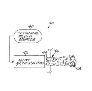
[0007] An aspect of the application is directed to a method for
decontaminating a small
enclosure, comprising the steps of: entering input parameters of the small
enclosure into a
processing unit, wherein the processing unit is programmed to determine fluid
properties of a
cleaning fluid in a decontamination device based on the input parameters of
the small enclosure,
activating a decontamination cycle of the decontamination device, wherein the
decontamination
cycle comprises the steps of: providing a reservoir of the cleaning fluid;
setting the determined
fluid properties of the cleaning fluid; generating a very dry mist comprising
ionized hydrogen
peroxide of the cleaning fluid, wherein the generated very dry mist is applied
to decontaminate
the small enclosure.
[0008] In certain embodiments, the decontamination device is operated
manually. In
particular embodiments, the decontamination device is hand-held.
[0009] In certain embodiments, the input parameters of the small enclosure
comprise:
dimensions of the small enclosure, a position of the decontamination device
relative to
boundaries of the small enclosure, air temperature, pressure, and humidity of
the small
enclosure. In particular embodiments, the set fluid properties of the cleaning
fluid comprise air
pressure and fluid flow rate. In other embodiments, the setting of the
determined fluid
properties to the cleaning fluid is performed by controlling an air valve. In
certain
embodiments, the air valve is controlled by programming the processing unit to
control a
potentiometer. In various embodiments, the determined fluid properties of the
cleaning fluid are
adjusted by a size and a shape of a tube located at an exit of the cleaning
fluid out of the
decontamination device.
[0010] In particular embodiments, the fluid properties of the cleaning fluid
are set by
lowering the air pressure and the fluid flow rate respectively below a
predetermined standard air
pressure and a predetermined standard fluid flow rate.
[0011] In other embodiments, input parameters of a target area are entered
into a
processing unit, wherein the processing unit is further programmed to
determine the fluid
properties of the cleaning fluid in the decontamination device based on the
input parameters of
the target area. The input parameters of the small enclosure may be manually
input. The input
parameters of the small enclosure are measured by a plurality of sensors that
are in networked
communication with the processing unit.
[0012] In particular embodiments, the processing unit and the decontamination
device
are in wireless communication.
[0013] Another aspect of the application is a system for decontaminating a
small
enclosure, comprising a decontamination device and a computer processor,
wherein the
2
CA 03087199 2020-06-26
WO 2019/133801 PCT/US2018/067843
computer processor is in networked communication with the decontamination
device, wherein
input parameters of the small enclosure are entered into the computer
processor, wherein the
computer processor is programmed to determine fluid properties of a cleaning
fluid in the
decontamination device based on the input parameters of the small enclosure,
wherein the
computer processor is further programmed to activate a decontamination cycle
of the
decontamination device, the decontamination cycle comprising the steps of:
providing a
reservoir of the cleaning fluid; setting the determined fluid properties of
the cleaning fluid;
generating a very dry mist of the cleaning fluid, wherein the generated very
dry mist is applied
to decontaminate the small enclosure.
[0014] These and other aspects and embodiments of the present application will
become
better understood with reference to the following detailed description when
considered in
association with the accompanying drawings and claims.
BRIEF DESCRIPTION OF THE DRAWINGS
[0015] FIG. 1 is a block flow diagram of a general approach for denaturing a
biochemical agent using an activated cleaning fluid mist.
[0016] FIG. 2 is a schematic view of a first embodiment of apparatus for
denaturing
biological agents, with the activator proximally located to the mist
generator.
[0017] FIG. 3 is a schematic view of a second embodiment of apparatus for
denaturing
biological agents, with the activator located remotely from the mist
generator.
[0018] FIG. 4 is a schematic view of a third embodiment of apparatus for
denaturing
biological agents, with both proximate and remote activators.
[0019] FIG. 5 illustrates a streaming decontamination apparatus.
[0020] FIG. 6 illustrates a chamber-based decontamination apparatus.
[0021] FIG. 7 illustrates a decontamination apparatus for decontaminating a
room.
[0022] FIG. 8 illustrates a decontamination apparatus for a heating,
ventilating, and air
conditioning duct system.
[0023] FIG. 9 illustrates a decontamination apparatus for air breathed by a
person.
[0024] FIG. 10A represents a configuration of device elements wherein a
cleaning fluid
source 40 and a mist generator 42 are linked via an actuating device 70 that
has an adjustable
range of rotation of up to 360 degrees. FIG. 10B represents a configuration of
device elements
wherein a cleaning fluid source 40 is interfaced with a mist generator 42
that, in turn, is linked to
a mist delivery unit 72 via an actuating device 70 that has an adjustable
range of rotation of up to
360 degrees. FIG. 10C represents a configuration of device elements wherein a
mist generator
42 is mounted on an actuating device 70 that has an adjustable range of
rotation of up to 360
degrees. FIG. 10D represents another configuration of device elements wherein
a mist generator
3
CA 03087199 2020-06-26
WO 2019/133801 PCT/US2018/067843
42 feeds into a mist delivery unit 72 that is mounted on an actuating device
70 that has an
adjustable range of rotation of up to 360 degrees.
[0025] FIG. 11A depicts an embodiment wherein at least a mist generator 42 and
a
voltage source 52 are contained within a portable housing. The mist generator
is functionally
connected to a mist delivery unit 72 which may be mounted on the housing or is
a remote unit.
FIG. 11B depicts a mist generator 42 and a voltage source 52 contained within
a portable
container, wherein the entire unit can be hand held, mounted on another
apparatus, or held
by/mounted on another machine or a robot. FIG. 11C depicts an exemplary
embodiment
wherein a mist generator 42and a voltage source 52 are contained within a
wearable container,
such as a back pack.
[0026] FIG. 12A illustrates the decontamination device comprises an ultrasonic
wafer 78
or ultrasonic nebulizer as a mist generator. FIG. 12B diagrams a system
wherein a
mobile/wireless/remote control device 84 is functionally connected to a
decontamination device
of the present disclosure, such as a nebulizer 82. FIG. 12C diagrams an
embodiment of the
system, wherein the system comprises multiple decontamination devices, such as
nebulizers,
that are controlled by a control device 84 and further communicate between the
nebulizers 82 by
wired or wireless means. Information from individual nebulizers 82 can be fed
back to the
control device 84 either en masse or individually. For example, the dosages
emitted by two
different nebulizers 82 may start or complete at different times and the data
can be reported
independently.
[0027] FIGS. 13A-B illustrates a similar system having a single (FIG. 13A) or
multiple
(FIG. 13B) mist generator(s) 42 being controlled by a control device 84, which
further provides
data 94 to an external source regarding the treatment of an area or surface.
[0028] FIG. 14 illustrates a system wherein a mist generator 42, cleaning
fluid source 40
and mist delivery unit 72 are further interfaced with a sensor 98.
[0029] FIG. 15 diagrams an exemplary rectifier for forming free radicals,
comprising a
voltage source 52, at least one diode/capacitor 102 interfaced with a plasma
actuator 76.
[0030] FIG. 16 depicts an embodiment of a mist generator 142 operable manually
as a
hand-held device and programmable for automated operation.
[0031] FIG. 17 depicts an embodiment of a display of a programming clock 143
regulating fluid properties of a fluid applied by a mist generator device,
[0032] Throughout the drawings, the same reference numerals and characters,
unless
otherwise stated are used to denote like features, elements, components or
portions of the
illustrated embodiments. Moreover, while the present disclosure will now be
described in detail
with reference to the figures, it is done so in connection with the
illustrative embodiments and is
4
not limited by the particular embodiments illustrated in the figures and
appended claims.
DETAILED DESCRIPTION
[0033] Reference will be made in detail to certain aspects and exemplary
embodiments
of the application, illustrating examples in the accompanying structures and
figures. The aspects
of the application are described in conjunction with the exemplary
embodiments, including
methods, materials and examples, such description is non-limiting and the
scope of the
application is intended to encompass all equivalents, alternatives, and
modifications, either
generally known, or described herein.
[0034] Unless defined otherwise, all technical and scientific tei ___ ins used
herein have the
same meanings as commonly understood by one of skill in the art to which the
disclosed method
and compositions belong. It must be noted that as used herein and in the
appended claims, the
singular forms "a," "an," and "the" include plural reference unless the
context clearly dictates
otherwise. Thus, for example, reference to "a peptide" includes "one or more"
peptides or a
"plurality" of such peptides.
[0035] Ranges may be expressed herein as from "about" one particular value,
and/or to
"about" another particular value. When such a range is expressed, another
embodiment includes
from the one particular value and/or to the other particular value. Similarly,
when values are
expressed as approximations, by use of the antecedent "about," it will be
understood that the
particular value forms another embodiment. It will be further understood that
the endpoints of
each of the ranges are significant both in relation to the other endpoint, and
independently of the
other endpoint. It is also understood that there are a number of values
disclosed herein, and that
each value is also herein disclosed as "about" that particular value in
addition to the value itself.
For example, if the value "10" is disclosed, then "about 10" is also
disclosed. It is also
understood that when a value is disclosed that "less than or equal to "the
value," greater than or
equal to the value" and possible ranges between values are also disclosed, as
appropriately
understood by the skilled artisan. For example, if the value "10" is disclosed
the "less than or
equal to 10" as well as "greater than or equal to 10" is also disclosed.
[0036] As used herein, the term "ultrasonic cavitation" means the use of
ultrasonic sound
to cavitate a fluid, such as a cleaning fluid. Ultrasonic cavitation can be
applied to a fluid by a
range of methods and devices known to one of skill in the art, including a
high pressure
ultrasonic nebulizer, an ultrasonic nozzle, or an ultrasonic wafer. As used
herein, the term
"ultrasonic" means frequencies of sound above the audible range, including
anything over
20kHz.
Date Recue/Date Received 2023-08-22
CA 03087199 2020-06-26
WO 2019/133801 PCT/US2018/067843
[0037] As used herein, the term "ultrasonic cavitator" means a device used to
perform
ultrasonic cavitation on a cleaning fluid. Examples of an ultrasonic cavitator
include a high
pressure ultrasonic nebulizer, an ultrasonic nozzle, or an ultrasonic wafer.
For example, a high
pressure ultrasonic nebulizer atomizes liquid particles at a pressure of 50 to
400 bar to produce
aerosol droplets. An ultrasonic nozzle is a spray nozzle that uses high
frequency vibration
produced by piezoelectric transducers to cavitate a liquid. A preferred
embodiment uses an
ultrasonic wafer. In one embodiment the ultrasonic wafer is a ceramic
diaphragm vibrating at an
ultrasonic frequency to create water droplets. In another embodiment, the
ultrasonic wafer is a
small metal plate that vibrates at high frequency to cavitate a liquid. One of
ordinary skill will
understand that the choice of ultrasonic cavitator is not limiting on the
scope of this application.
[0038] As used herein, the term "decontaminating" means acting to neutralize
or remove
pathogens from an area or article. As used herein, the term "pathogen"
includes, but is not
limited to, a bacterium, yeast, protozoan, virus, or other pathogenic
microorganisms. The teim
"pathogen" also encompasses targeted bioterror agents.
[0039] As used herein, the term "bacteria" shall mean members of a large group
of
unicellular microorganisms that have cell walls but lack organelles and an
organized nucleus.
Synonyms for bacteria may include the terms "microorganisms", "microbes",
"germs", "bacilli",
and "prokaryotes." Exemplary bacteria include, but are not limited to
Mycobacterium species,
including M. tuberculosis; Staphylococcus species, including S. epidermidis,
S. aureus, and
methicillin-resistant S. aureus; Streptococcus species, including S.
pneumoniae, S. pyogenes, S.
mutans, S. agalactiae, S. equi, S. canis, S. bovis, S. equinus, S. anginosus,
S. sanguis, S.
salivarius, S. mitis; other pathogenic Streptococcal species, including
Enterococcus species,
such as E. faecalis and E. faecium; Haemophilus influenzae, Pseudomonas
species, including P.
aeruginosa, P. pseudomallei, and P. mallei; Salmonella species, including S.
enterocolitis, S.
typhimurium, S. enteritidis, S. bongori, and S. choleraesuis; Shigella
species, including S.
flexneri, S. sonnei, S. dysenteriae, and S. boydii; Brucella species,
including B. melitensis, B.
suis, B. abortus, and B. pertussis; Neisseria species, including N.
meningitidis and N.
gonorrhoeae; Escherichia coli, including enterotoxigenic E. coli (E l'EC);
Vibrio cholerae,
Helicobacter pylori, Geobacillus stearothermophilus, Chlamydia trachomatis,
Clostridium
Cryptococcus neoformans, Moraxella species, including M. catarrhalis,
Campylobacter
species, including C. jejuni; Corynebacterium species, including C.
diphtheriae, C. ulcerans, C.
pseudotuberculosis, C. pseudodiphtheriticum, C. urealyticum, C. hemolyticum,
C. equi; Listeria
monocytogenes, Nocardia asteroides, Bacteroides species, Actinomycetes
species, Treponema
pallidum, Leptospirosa species, Klebsiella pneumoniae; Proteus sp., including
Proteus vulgaris;
Serratia species, Acinetobacter, Yersinia species, including Y. pestis and Y.
pseudotuberculosis;
6
CA 03087199 2020-06-26
WO 2019/133801 PCT/US2018/067843
Francisella tularensis, Enterobacter species, Bacteriodes species, Legionella
species, Borrelia
burgdorferi, and the like. As used herein, the term "targeted bioterror
agents" includes, but is
not limited to, anthrax (Bacillus antracis), plague (Yersinia pestis), and
tularemia (Franciscella
tularensis).
[0040] As used herein, the term "virus" can include, but is not limited to,
influenza
viruses, herpesviruses, polioviruses, noroviruses, and retroviruses. Examples
of viruses include,
but are not limited to, human immunodeficiency virus type 1 and type 2 (HIV-1
and HIV-2),
human T-cell lymphotropic virus type I and type II (HTLV-I and HTLV-II),
hepatitis A virus,
hepatitis B virus (HBV), hepatitis C virus (HCV), hepatitis delta virus (HDV),
hepatitis E virus
(HEV), hepatitis G virus (HGV), parvovirus B19 virus, hepatitis A virus,
hepatitis G virus,
hepatitis E virus, transfusion transmitted virus (TTV), Epstein-Barr virus,
human
cytomegalovirus type 1 (HCMV-1), human herpesvirus type 6 (HHV-6), human
herpesvirus
type 7 (HHV-7), human herpesvirus type 8 (HHV-8), influenza type A viruses,
including
subtypes H1N1 and H5N1, human metapneumovirus, severe acute respiratory
syndrome
(SARS) coronavirus, hantavirus, and RNA viruses from Arenaviridae (e.g., Lassa
fever virus
(LFV)), Pneumoviridae (e.g., human metapneumovirus), Filoviridae (e.g., Ebola
virus (EBOV),
Marburg virus (MBGV) and Zika virus); Bunyaviridae (e.g., Rift Valley fever
virus (RVFV),
Crimean-Congo hemorrhagic fever virus (CCHFV), and hantavirus); Flaviviridae
(West Nile
virus (WNV), Dengue fever virus (DENY), yellow fever virus (YFV), GB virus C
(GBV-C;
formerly known as hepatitis G virus (HGV)); Rotaviridae (e.g., rotavirus), and
combinations
thereof In one embodiment, the subject is infected with HIV-1 or HIV-2.
[0041] As used herein, the term "fungi" shall mean any member of the group of
saprophytic and parasitic spore-producing eukaryotic typically filamentous
organisms formerly
classified as plants that lack chlorophyll and include molds, rusts, mildews,
smuts, mushrooms,
and yeasts. Exemplary fungi include, but are not limited to, Aspergillus
species,
Dermatophytes, Blastomyces derinatitidis, Candida species, including C. auris,
C. albicans and
C.krusei; Malassezia furfur, Exophiala werneckii, Piedraia hortai,
Trichosporon beigelii,
Pseudallescheria boydii, Madurella grisea, Histoplasma capsulatum, Sporothrix
schenckii,
Histoplasma capsulatum, Tinea species, including T. versicolor, T. pedis T.
unguium, T. cruris,
T. capitus, T. corporis, T. barbae; Trichophyton species, including T. rubrum,
T. interdigitale, T.
tonsurans, T. violaceum, T. yaoundei, T. schoenleinii, T. megninii, T.
soudanense, T. equinum,
T. erinacei, and T. verrucosum; Mycoplasma genitalia; Microspon.tm species,
including M.
audouini, M. ferrugineutn, M. canis, M. nanum, M. distortum, M. gypseum, M.
fulvum, and the
like.
[0042] As used herein, the term "protozoan" shall mean any member of a diverse
group
7
CA 03087199 2020-06-26
WO 2019/133801 PCT/US2018/067843
of eukaryotes that are primarily unicellular, existing singly or aggregating
into colonies, are
usually nonphotosynthetic, and are often classified further into phyla
according to their capacity
for and means of motility, as by pseudopods, flagella, or cilia. Exemplary
protozoans include,
but are not limited to Plasmodium species, including P. falciparum, P. vivax,
P. ovale, and P.
malariae; Leishmania species, including L. major, L. tropica, L. donovani, L.
infantum, L.
chagasi, L. mexicana, L. panamensis, L. braziliensis and L. guyanensi;
Cryptosporidium,
Isospora belli, Toxoplasma gondii, Trichomonas vaginalis, and Cyclospora
species.
[0043] As used herein, the term "article" means any solid item or object that
may be
susceptible to contamination with pathogens. As used herein, the term
"substantially enclosed
space" means a room, a tent, a building, or any man-made structure that is
substantially enclosed
and may be susceptible to contamination with pathogens. The term
"substantially enclosed
space" is not limited to man-made structures, even though embodiments
illustrated herein may
be preferably directed to decontamination of such structures
[0044] As used herein, the term "sensor" can refer to any type of sensor
suitable for
detecting contamination on an apparatus, a surface, or in a substantially
closed space. Examples
of sensors include, but are not limited to, photosensors, voltaic sensors,
weight sensors, moisture
sensors, pressure sensors, or any type of biosensor.
[0045] As used herein, the term "shearing" refers to the process of using
force to
fragment liquid particles into discrete groups that move and flow as energized
independent sub-
groups of sheared particles until the groups of particles transition in fluid
phase into a mist. As
used herein, the term "mist" means a cloud of aerosol droplets. As used
herein, the term
"aerosol" is a colloid of fine liquid droplets of about 1 to about 20
micrometers in diameter.
[0046] As used herein, the mini "cleaning fluid" refers to the source of an
active species
used to decontaminate an article or substantially enclosed space. The
preferred active species is
hydroxyl ions, and the preferred source is hydrogen peroxide. The source may
instead be a
more-complex species that produces hydroxyl ions upon reaction or
decomposition. Examples
of such more-complex species include peracetic acid (CH2C00-0H+H20), sodium
percarbonate (2Na2CO3+3H202), and gluteraldehyde (CH802). The cleaning fluid
may further
include promoting species that aid the active species in accomplishing its
attack upon the
biological microorganisms. Examples of such promoting species include
ethylenediaminetetraacetate, isopropyl alcohol, enzymes, fatty acids, and
acids. The cleaning
fluid is of any operable type. The cleaning fluid must contain an activatable
species. A
preferred cleaning fluid comprises a source of hydroxyl ions (OH) for
subsequent activation.
Such a source may be hydrogen peroxide (H202) or a precursor species that
produces hydroxyl
ions. Other sources of hydroxyl ions may be used as appropriate. Examples of
other operable
8
CA 03087199 2020-06-26
WO 2019/133801 PCT/US2018/067843
sources of hydroxyl ions include peracetic acid (CH2C00--0H+H20), sodium
percarbonate
(2Na2CO3+3H202), and gluteraldehyde (CH802). Other activatable species and
sources of such
other activatable species may also be used. In some embodiments, activated
ionic particles are
generated by passing Water for Injection (WFI) through the arc, providing
greater than 3-log10
killing of bacteria, bacterial spores, or virus particles relative to
untreated controls.
[0047] The cleaning fluid may also contain promoting species that are not
themselves
sources of activatable species such as hydroxyl ions, but instead modify the
decontamination
reactions in some beneficial fashion. Examples include
ethylenediaminetetraacetate (EDTA),
which binds metal ions and allows the activated species to destroy the cell
walls more readily;
an alcohol such as isopropyl alcohol, which improves wetting of the mist to
the cells; enzymes,
which speed up or intensity the redox reaction in which the activated species
attacks the cell
walls; fatty acids, which act as an ancillary anti-microbial and may combine
with free radicals to
create residual anti-microbial activity; and acids such as citric acid, lactic
acid, or oxalic acid,
which speed up or intensity the redox reaction and may act as ancillary anti-
microbial species to
pH-sensitive organisms. Mixtures of the various activatable species and the
various promoting
species may be used as well. The cleaning fluids are preferably aqueous
solutions, but may be
solutions in organics such as alcohol. The cleaning fluid source may be a
source of the cleaning
fluid itself, or a source of a cleaning fluid precursor that chemically reacts
or decomposes to
produce the cleaning fluid.
[0048] As used herein, the term "a nonthermal plasma actuator" means an
actuator that
activates the cleaning fluid to an activated condition such as the ionized,
plasma, or free radical
states which, with the passage of time, returns to the non-activated state (a
process termed
"recombination"). To accomplish the activation, the activator produces
activating energy such
as electric energy or photonic energy. The photonic energy may be produced by
a laser.
Examples of activators include an AC electric field, an AC arc, a DC electric
field, a DC arc, an
electron beam, an ion beam, a microwave beam, a radio frequency beam, and an
ultraviolet light
beam. The activator may include a tuner that tunes the amplitude, frequency,
wave form, or
other characteristic of the activating energy to achieve a desired, usually a
maximum, re-
combination time of the activated cleaning fluid mist. As used herein, the
term "plasma
activated ionic particles" means activated OH ions.
[0049] As used herein, an "enclosed space" refers to any chamber, container or
space
that can be decontaminated with the system of the present disclosure. Examples
of enclosed
spaces include, but are not limited to, any chamber used in everyday to highly
controlled
research projects/spaces, sanitation chambers (such as gynoprobe cabinets),
BSC, glovebox,
research hoods and clinical spaces.
9
CA 03087199 2020-06-26
WO 2019/133801 PCT/US2018/067843
A System for Decontaminating a Substantially Enclosed Space of an Airborne
Pathogen
[0050] An aspect of the application is a system for decontaminating a
substantially
enclosed space, comprising: a sensor for airborne pathogens, wherein the
sensor is in networked
communication with a computer processor; a computer processor, wherein the
computer
processor is in networked communication with the sensor and a decontamination
apparatus; a
decontamination apparatus, wherein the decontamination apparatus is in
networked
communication with the computer processor, and further wherein the
decontamination apparatus
comprises: a reservoir of cleaning fluid; an ultrasonic cavitator, wherein the
ultrasonic cavitator
is submerged in the reservoir; a nonthermal plasma actuator, wherein the
actuator activates a
mist generated from the reservoir; a funnel, wherein the funnel connects the
nonthermal plasma
activator to the reservoir; an outer tube, wherein the outer tube connects the
nonthermal actuator
to the external atmosphere; and wherein a mist generated from the reservoir
can pass through the
funnel to the actuator, and further wherein after the mist is activated by the
actuator the mist can
pass through the outer tube to the external atmosphere.
[0051] In an exemplary embodiment, the computer system includes a memory, a
processor, and, optionally, a secondary storage device. In some embodiments,
the computer
system includes a plurality of processors and is configured as a plurality of,
e.g., bladed servers,
or other known server configurations. In particular embodiments, the computer
system also
includes an input device, a display device, and an output device. In some
embodiments, the
memory includes RAM or similar types of memory. In particular embodiments, the
memory
stores one or more applications for execution by the processor. In some
embodiments, the
secondary storage device includes a hard disk drive, CD-ROM or DVD drive, or
other types of
non-volatile data storage. In particular embodiments, the processor executes
the application(s)
that are stored in the memory or the secondary storage, or received from the
internet or other
network. In some embodiments, processing by the processor may be implemented
in software,
such as software modules, for execution by computers or other machines. These
applications
preferably include instructions executable to perform the functions and
methods described above
and illustrated in the Figures herein. The applications preferably provide
GUIs through which
users may view and interact with the application(s). In other embodiments, the
system
comprises remote access to control and/or view the system.
[0052] In further embodiments, a decontamination system can interface with a
building
HVAC system for room isolation and aeration. The decontamination system uses
automated
equipment for decontamination of any closed area with downloadable
disinfection/decontamination run data and real-time measurement of injection
rates to ensure
targeted injection volume. The decontamination system can encompass multiple
rooms and
customized specifications as required according to room size and usage. In
another
embodiment, the decontamination system is contained in a handheld device for
use in a life
science facility. The device is designed to be used by technicians using a
trigger on the device
to control its use according to the trigger position.
Method and Apparatus for Decontamination Using an Activated Cleaning Fluid
Mist
[0053] As disclosed in U.S. Patent No. 6,969,487, a method for performing
decontamination comprises the steps of producing an activated cleaning fluid
mist wherein at
least a portion of the cleaning fluid mist is in an activated state, and
contacting the activated
cleaning fluid mist to a location to be decontaminated.
[0054] FIG. 1 depicts a preferred method for performing decontamination. An
activated
cleaning fluid mist is produced, numeral 20. Any operable approach may be
used, and a
preferred approach is illustrated within step 20 of FIG. 1. A source of a
cleaning fluid is
provided, numeral 22. The cleaning fluid is preferably a liquid that may be
vaporized, by any
means of force or energy, in ambient-pressure air to form a mist. The liquid
cleaning fluid may
be stored at one atmosphere or slightly greater pressure, while a cleaning
fluid in a gaseous state
usually requires pressurized storage. The source of the cleaning fluid may
also be a precursor of
the cleaning fluid, such as a solid, liquid, or gas that reacts, decomposes,
or otherwise produces
the cleaning fluid.
[0055] A cleaning fluid mist, containing the activatable species and the
promoting
species, if any, is generated, numeral 24. The mist generator to generate the
cleaning fluid mist
may be of any operable type. In the preferred case, the cleaning mist or vapor
is fine droplets of
the vaporized cleaning fluid. In some embodiments, the droplets are preferably
roughly
uniformly sized, on the order of from about 1 to about 20 micrometers in
diameter. In other
embodiments, the droplets are preferably roughly uniformly sized, on the order
of from about 1
to about 10 micrometers in diameter. In still other embodiments, the droplets
are preferably
roughly uniformly sized, on the order of from about 1 to about 5 micrometers
in diameter. In
yet other embodiments, the droplets are preferably roughly uniformly sized, on
the order of from
about 2 to about 4 micrometers in diameter. Various types of mist generators
have been used in
prototype studies.
[0056] The cleaning fluid mist is activated to produce an activated cleaning
fluid mist,
numeral 26. The activation produces activated species of the cleaning fluid
material in the mist,
such as the cleaning fluid material in the ionized, plasma, or free radical
states. At least a
portion of the activatable species is activated, and in some cases some of the
promoting species,
if any, is activated. A high yield of activated species is desired to improve
the efficiency of the
11
Date Recue/Date Received 2022-11-23
CA 03087199 2020-06-26
WO 2019/133801 PCT/US2018/067843
decontamination process, but it is not necessary that all or even a majority
of the activatable
species achieve the activated state. Any operable activator may be used. The
activator field or
beam may be electrical or photonic. Examples include an AC electric field, an
AC arc, a DC
electric field, a DC arc, an electron beam, an ion beam, a microwave beam, a
radio frequency
beam, and an ultraviolet light beam produced by a laser or other source. The
activator causes at
least some of the activatable species of the cleaning fluid in the cleaning
fluid mist to be excited
to the ion, plasma, or free radical state, thereby achieving "activation."
These activated species
enter redox reactions with the cell walls of the microbiological organisms,
thereby destroying
the cells or at least preventing their multiplication and growth. In the case
of the preferred
hydrogen peroxide, at least some of the H202 molecules dissociate to produce
hydroxyl (OH)
and monatomic oxygen (0) ionic activated species. These activated species
remain dissociated
for a period of time, typically several seconds or longer, during which they
attack and destroy
the biological microorganisms. The activator is preferably tunable as to the
frequency,
waveform, amplitude, or other properties of the activation field or beam, so
that it may be
optimized for achieving a maximum recombination time for action against the
biological
microorganisms. In the case of hydrogen peroxide, the dissociated activated
species recombine
to form diatomic oxygen and water, harmless molecules.
[0057] The physical relationship of the mist generator and the activator may
be of
several types, illustrated schematically for three types of decontamination
apparatus 38 in FIGS.
2-4. A source of the cleaning fluid 40 provides a flow of the cleaning fluid
to a mist generator
42 in each case. The mist generator forms a cleaning fluid mist 44 of the
cleaning fluid. The
cleaning fluid mist 44 includes the activatable species and the promoting
species, if any. In the
embodiment of FIG. 2, an activator 46, schematically illustrated as a pair of
electrical discharge
plates between which the cleaning fluid mist 44 passes, is located proximate
to, and preferably
immediately adjacent to, the mist generator 42. The mist generator 42 and the
activator 46 are
typically packaged together for convenience in a single housing in this case.
The cleaning fluid
mist 44 leaving the mist generator 42 is immediately activated by the
activator 46 to produce an
activated cleaning fluid mist 48. In the embodiment of FIG. 3, the activator
46, here
schematically illustrated as a set of microwave sources, is located remotely
from the mist
generator 42. The cleaning fluid mist 44 flows from mist generator 42 and
remains as a non-
activated cleaning fluid mist for a period of time, prior to passing into a
region where it is in the
influence of and activated by the activator 46. These two embodiments may be
combined as
shown in FIG. 4, where the cleaning fluid mist 44 is initially activated to
form the activated
cleaning fluid mist 48 by an activator 46a that is proximate to the mist
generator 42, and then
kept in the activated state or re-activated as necessary by an activator 46b
that is remote from the
12
CA 03087199 2020-06-26
WO 2019/133801 PCT/US2018/067843
mist generator 42. In this case, the activator 46b is illustrated to be an
ultraviolet light source.
The apparatus of FIG. 4 has the advantage that the cleaning fluid is initially
activated and then
maintained in an activated state for an extended period of time to achieve a
prolonged effective
state. These various types of apparatus 38 are used in differing situations
according to the
physical constraints of each situation, and some illustrative situations are
discussed
subsequently. Particle and/or gas filters may be provided where appropriate to
remove
particulate matter that is the carrier for microbiological organisms, and also
to remove the
residual cleaning mist and its reaction products.
[0058] The activated cleaning fluid mist 48 is contacted to locations that are
to be
decontaminated, numeral 28. The types of locations and the manner of
contacting lead to a
number of specific embodiments of the previously described general approaches,
as described
next.
[0059] FIG. 5 illustrates a streaming form of decontamination apparatus 38.
This type of
apparatus normally uses the general configuration shown in FIG. 2, where the
activator 46 is
located proximally to the mist generator 42. It does not require an enclosure,
although it may be
used within an enclosure. In FIG. 5 and other figures illustrating specific
embodiments of the
apparatus, the common elements of structure will be given the same reference
numerals as used
elsewhere, and the other description is incorporated into the description of
each embodiment.
Cleaning fluid from the cleaning fluid source 40 is supplied to the mist
generator 42, and the
cleaning fluid mist 44 flows from the mist generator 42. The cleaning fluid
mist 44 flows
through an interior of a tube 50 that channels and directs the flow of the
cleaning fluid mist 44.
The activator 46 powered by a voltage source 52 activates the cleaning fluid
mist 44 as it flows
through the interior of the tube 50, so that the activated cleaning fluid mist
48 flows from the
tube 50 as a stream. The stream is directed into a volume or against an object
that is to be
decontaminated.
100601 In one embodiment, the voltage source 52 is connected to an adjustable
voltage
divider, such as a potentiometer, for example. The potentiometer may include a
housing that
contains a resistive element and a contact that slides along the resistive
element, two electrical
terminals at the two ends of the resistive element, and a mechanism that moves
the sliding
contact from one end to the other. The potentiometer used may be a circular
slider
potentiometer, a liner slider potentiometer, or any other suitable slider
arrangement may be used.
The potentiometer may include a resistive element made of graphite, plastic
containing carbon
particles, resistance wire, or a mixture of ceramic and metal, for example.
[0061] The included potentiometer may allow a user to control the fluid flow
rate of the
cleaning fluid mist 44 flowing through the tube 50. As a result, the reduced
air pressure may
13
CA 03087199 2020-06-26
WO 2019/133801 PCT/US2018/067843
reduce the size of the produced mist/fog particle. This potentiometer may be
controlled by a
control unit in order to regulate input for the electric circuit of the
voltage source 52.
[0062] This basic configuration of FIG. 5 may be scaled over a wide range of
sizes. In
one example, the cleaning fluid source 40 is a hand-held pressure can of the
type commonly
used to dispense fluids or gases. In another example, the cleaning fluid
source 40 operates on
two platforms, for example. One platform may be a handheld, point-and-spray
surface
decontamination device, and the other platform may be a programmable,
automated
environment decontamination device designed for small enclosures. The
handheld, point-and-
spray feature allows for manual control of the decontamination action. The
programmable
automation allows input of the surrounding parameters in order to predictably
and consistently
operate in an optimal arrangement with the geometry of the decontaminate
enclosure.
[0063] The voltage source 52 is a battery and a circuit to supply a high
voltage to the
activation source 46 for a sufficient period to activate the amount of
cleaning fluid that is stored
within the pressure can. The tube 50 is the nozzle of the pressure can. In
another example, the
tube 50 is a hand-held wand operating from a larger-volume cleaning fluid
source 40 and with a
plug-in or battery electrical voltage source 52. The cleaning fluid source 40
may be pressurized
to drive the flow of the cleaning fluid through the tube 50, or there may be
provided an optional
pump 54 that forces the cleaning fluid through the mist generator 42 and out
of the tube 50 with
great force.
[0064] In a programmable device, the control unit may be programmed to send
instruction to adjust the potentiometer and control the pump 54 based on the
desired fluid
parameters. For example, in particularly small enclosures, a drier mist may be
generated, in
order for the mist to travel a shorter distance. This may be accomplished by
reducing the
standard air pressure, or the standard fluid flow rate of the decontamination
device. The
standard air pressure entered into the programmable control unit may be in the
range between
25-50 psi, and the input standard air pressure range may be modified as deemed
suitable. In
addition, the standard fluid flow rate entered into the programmable control
unit may be in the
range between 25-50 ml/minute, and the input standard fluid flow rate range
may be modified as
considered appropriate.
[0065] In comparison with the programmable device, a handheld surface
decontamination device may be manually operated by pressing the trigger on a
handheld
applicator to produce the decontamination fluid, such as ionized hydrogen
peroxide mist. In one
example, fluid or air settings are not programably modified, but are, instead,
manually controlled
by the user based on the actual confines of the enclosure.
[0066] Other forms of the apparatus 38 are primarily used in conjunction with
an
14
CA 03087199 2020-06-26
WO 2019/133801 PCT/US2018/067843
enclosure, either to enclose the decontamination processing or an object or
flow, or to achieve
decontamination of the interior of the enclosure. FIG. 6 illustrates the
apparatus 38 including an
enclosure 56 that serves as a chamber in which an object 58 is decontaminated.
The object 58
may be stationary, or it may move through the enclosure 56 on a conveyer. This
embodiment
also illustrates the form of the present apparatus wherein the activated
cleaning fluid mist 48 is
added to and mixed with another gas flow 60. The activated cleaning fluid mist
48 mixes with
the gas flow 60, and the mixed gas flow contacts the object 58. This
embodiment may be
implemented either as a continuous-flow system, as illustrated, or as a batch
system wherein the
enclosure 56 is filled with the activated cleaning fluid mist 48 or with the
mixture of the
activated cleaning fluid mist 48 and the gas 60 in a batch-wise fashion.
[0067] In the embodiment of FIG. 7, the enclosure 56 is formed by the walls,
floor, and
ceiling of a room or other structure such as a vehicle. The activated cleaning
fluid mist is
produced by an integrated apparatus of the type illustrated in FIG. 4, in
which the mist generator
42 and the activator 46a are packaged together as a single unit. An optional
second activator
46b is provided and used in the manner described in relation to FIG. 4, whose
disclosure is
incorporated here. The second activator 46b maintains the activated cleaning
fluid mist in the
activated state for extended periods of time, so as to allow complete
decontamination of the
room. The second activator 46b may be built into the walls, floor, or ceiling
of the enclosure 56,
or they may be provided as portable units that are positioned within the
enclosure 56 only during
the decontamination processing. The decontamination apparatus 38 of FIG. 7
decontaminates
the interior walls of the room, vehicle, or other structure, as well as
objects and people therein.
An apparatus 38 of the type shown in FIG. 7 may be used to decontaminate a
room (or rooms) in
a stationary home, office, or other facility, or the interior of a movable
vehicle such as an
aircraft, automobile, ship, or military vehicle. The enclosure 56 may also be
a protective suit
worn by decontamination personnel, to provide continuing decontamination of
its interior for
normal operation or in the event of a leak in the protective suit.
[0068] FIG. 8 illustrates an embodiment wherein the mist generator 42 and the
activator
46 are built into, or temporarily inserted into, an enclosure 56 in the form
of a duct of the HVAC
system. The duct 62 may be part of the main duct of the HVAC system, or it may
be an
auxiliary duct added to the HVAC system for receiving the decontamination
apparatus 38. A
filter 64 is provided downstream of the mist generator 42 and activator 46 for
removing
particulate and any remaining mist. The filter 64 may be, for example, a
porous carbon, low-
restriction coalescing filter of the known type.
[0069] As illustrated by the embodiment of FIG. 8, the decontamination
apparatus 38
may be used to decontaminate air and other gas flows, in addition to solid
objects. FIG. 9
CA 03087199 2020-06-26
WO 2019/133801 PCT/US2018/067843
illustrates an embodiment wherein the decontamination apparatus 38 is used in
the manner of a
gas mask to furnish decontaminated breathing air for a person. The enclosure
56 is structured as
a cannister having an air intake and an outlet providing air to a face mask 66
placed over the
face of a person. The cleaning fluid mist is injected into the incoming air by
the mist generator
42. The activator 46 may be positioned to activate the cleaning fluid mist in
the manner of FIG.
2. Instead, in this case the activator 46 is positioned downstream of the air
intake so that the
cleaning fluid mist is first thoroughly mixed with the incoming air and
thereafter activated by
the activator 46. The filter 64 is provided as discussed earlier to remove
particulate and any
liquid remnants of the mist.
[0070] Some embodiments of the present disclosure operate in an ambient
pressure of
about one atmosphere or slightly above one atmosphere, all of which are within
the scope of
"substantially one atmosphere ambient pressure". As noted earlier, this
capability is important
because most decontamination situations require the ability to achieve the
decontamination
without setting up vacuum chambers or pressure chambers. The mist generator
produces a small
overpressure of the mist as it enters the one atmosphere environment, but does
not require either
a vacuum or a pressure chamber. Especially in embodiments such as those of
FIGS. 3, 4, 6, 8,
and 9, particulate matter may be removed from the contaminated region or
contaminated gas
flow and collected on filters, thereby removing the carrier medium of the
microbiological
organisms as well as destroying the exposed microbiological organisms
themselves.
Decontamination Method
[0071] One aspect of the application relates to a method for decontaminating
an article
or substantially enclosed space, comprising the steps of: shearing a cleaning
fluid into a mist
comprising aerosol droplets accumulating in a top chamber portion of a
substantially closed
chamber comprising a funnel shaped top chamber portion, a bottom chamber
portion, a side
chamber portion and an interior chamber portion, wherein the cleaning fluid is
sheared by
ultrasonic cavitation; subjecting the mist to a nonthermal plasma actuator to
form plasma
activated ionic particles; and contacting the article or substantially
enclosed space to the plasma
activated ionic particles. One of ordinary skill will understand that the
foim, such as a funnel
shaped top chamber, or factor of the aerolized method of applying plasma
activated ionic
particles is not limiting on the application.
[0072] Another aspect of the application relates to a method for
decontaminating an
article or substantially enclosed space, comprising the steps of: shearing a
cleaning fluid into a
mist comprising aerosol droplets by cavitating the cleaning fluid using an
ultrasonic cavitator
submerged in a substantially closed chamber comprising the cleaning fluid;
subjecting the mist
to a nonthermal plasma actuator in an outlet tube extending from an opening in
a top chamber
16
CA 03087199 2020-06-26
WO 2019/133801
PCT/US2018/067843
portion of the substantially closed chamber, wherein the outlet tube comprises
a hollow lumen
with a distal opening above the top chamber portion for expelling the aerosol
droplets to form
plasma activated ionic particles; and contacting the article or substantially
enclosed space to the
plasma activated ionic particles.
100731 A further aspect of the application is a method for decontaminating an
article or
substantially enclosed space, comprising the steps of: submerging an
ultrasonic cavitator in a
reservoir of a cleaning fluid; cavitating the cleaning fluid with ultrasonic
vibrations produced by
the ultrasonic cavitator; generating a mist comprising aerosol droplets,
wherein the mist is
generated from the cleaning fluid while the cleaning fluid is being cavitated;
subjecting the mist
to a nonthermal plasma actuator to form plasma activated ionic particles; and
contacting the
plasma activated ionic particles to a pathogen.
[0074] Another aspect of the application relates to a method for
decontaminating an
article or substantially enclosed space, comprising the steps of: providing a
reservoir of a
cleaning fluid; cavitating the reservoir of cleaning fluid by applying force
to the cleaning fluid;
generating a mist comprising aerosol droplets, wherein the mist is generated
from the cleaning
fluid while the cleaning fluid is subject to cavitation by force; subjecting
the mist to a
nonthermal plasma actuator to form plasma activated ionic particles; and
contacting the plasma
activated ionic particles to a pathogen.
[0075] The present disclosure provides a method of decontaminating an article
or
substantially enclosed space by ultrasonic cavitation. The present application
discloses that the
use of ultrasonic cavitation within the cleaning fluid unexpectedly results in
a low pressure, low
fluid flow mist that significantly enhances kill performance and the ability
to decontaminate
tightly enclosed environments once the mist has been activated. The method
also
advantageously reduces the complexity of the machinery used in decontaminating
processes as
no air compression is required.
Decontamination Devices
[0076] Exemplary decontamination devices/systems of the present disclosure
comprise
an applicator having a cold plasma arc that splits a hydrogen peroxide-based
solution into
reactive oxygen species, including hydroxyl radicals, that seek, kill, and
render pathogens
inactive. The activated particles generated by the applicator kill or
inactivate a broad spectrum
of pathogens and are safe for sensitive equipment. In general, decontamination
devices/systems
of the present disclosure allow the effective treatment of an exemplary space
measuring 104 m2
in about 75 minutes, including application time, contact time, and aeration
time.
Decontamination devices/systems of the present disclosure are scalable and
configurable to be
effective in any size or volume of space/room/chamber/container. The
scalability may be
17
CA 03087199 2020-06-26
WO 2019/133801 PCT/US2018/067843
accomplished by the size of the device, by the manual control of the
decontamination fluid, or
by programming the air pressure of the device and the consequent fluid flow
rate as a function of
the input space/room/chamber/container parameters.
[0077] Exemplary spaces include, but are not limited to, clean rooms, research
laboratories, production environments, service & technical areas (HEPA
filters), material pass-
through rooms, corridors and thoroughfares. The decontamination
devices/systems of the
present disclosure are applicable to areas from a single space to an entire
building. The plasma
activated ionic particles generated by the present device or system are non-
caustic and silver
free. In general, the mist generated by the present device or system moves
through an enclosed
space or over a surface. Exemplary surfaces that can be decontaminated
include, but are not
limited to, safety cabinets, general laboratory equipment, isolators, HEPA
filters, Vivarium
caging, and decommissioned equipment.
[0078] Another aspect of the present application relates to miniature
decontamination
devices that comprise a DCV miniature transformer and/or a DCV miniature
compressor to
reduce power demand and overall weight and size of the device. In some
embodiments, a
miniature decontamination device has that may be lunchbox-sized to backpack-
sized, and/or has
a weight in the range of 10-40 lb. In some embodiments, the miniature
decontamination device
is placed in a backpack, a lightweight portable case or on a wheeled cart. In
certain
embodiments, the device comprises a small chamber system that heats the
decontaminating
solution to cause vaporization before passing through the arc system. In
particular
embodiments, the device comprises a rechargeable battery operated portable
wheeled system
(similar in form to an IV stand-type system).
[0079] In some embodiments, the DCV miniature transformer has an input DC
voltage
in the range of 6-36V and generates an output of 12-22.5 kV. In some
embodiments, the DCV
miniature transformer has an input DC voltage of 24V and generates an output
of 17.5kV.
[0080] In some embodiments, the DCV miniature compressor provides a pressure
in the
range of 10-60 psi and has an input DC voltage in the range of 6-36V. In some
embodiments,
the DCV miniature compressor provides a pressure in the range of 30-40 psi and
has an input
DC voltage of 24V.
[0081] In some embodiments, the miniature decontamination device further
comprises a
diode/capacitor rectifier that smooths out arc converting process and
increases the converting
efficiency in AC.
[0082] In some embodiments, the miniature decontamination device further
comprises
low flow pump with a flow rate in the range of 4-40 ml/min and an operating
voltage in the
range of 6-36VDC.
18
CA 03087199 2020-06-26
WO 2019/133801 PCT/US2018/067843
[0083] In some embodiments, the miniature decontamination device further
contains a
control module that allows control (e.g., start and or stop the device) and
monitoring of the
miniature decontaminating device from a remote device such as a tablet or a
phone. In some
embodiments, the control module further controls data storage, transfer and
printing.
[0084] Another aspect of the present application relates to a miniature
decontamination
device that comprises a miniature transformer and an ultrasonic wafer or
ultrasonic nebulizer as
a mist generator. In some embodiments, the mist generator comprises a
substantially closed
sonication chamber that comprises a funnel shaped top chamber portion, a
bottom chamber
portion, a side chamber portion and an interior chamber portion, wherein the
cleaning fluid is
sheared by ultrasonic cavitation within the sonication chamber. In some
embodiments, the
device comprises more than one ultrasonic wafer. In some further embodiments,
the device
comprises 2, 3, 4, 5, 6, 7, 8, 9, or 10 ultrasonic wafers.
[0085] In some embodiments, the decontamination device has a modular structure
that
reduces the footprint of the device and allows exchange of modules between
different devices.
[0086] In some embodiments, the decontamination device further comprises low
flow
pump with a flow rate in the range of 4-40 ml/min and an operating voltage in
the range of 6-
36VDC or 10-28 VDC.
[0087] In some embodiments, the decontamination device further contains a
control
module that allows control (e.g., start and or stop the device) and monitoring
of the miniature
decontaminating device from a remote device such as a tablet or a phone. hi
some
embodiments, the control module further controls data storage, transfer and
printing. In some
embodiments, the control module allows for remote service and connection, for
recording video
or data, and for providing feedback to the user during use or after use.
[0088] In some embodiments, the decontamination device is mounted on a
rotating base
that allows better coverage for the area to be decontaminated, as illustrated
in the diagrams of
FIGS. 10A-D. In some embodiments, the rotating base is a 180-degree rotating
base. In some
embodiments, the rotating base is a 360-degree rotating base. In some
embodiments, the
rotating base is an adjustable rotating base having a rotation range of 60-360
degrees. In some
embodiments, the rotation is around a single axis. In other embodiments, the
rotation is around
multiple axes. In still other embodiments, the rotation is in all directions
or is a fully spherical
motion. FIG. 10A represents a configuration of device elements wherein a
cleaning fluid source
40 and a mist generator 42 are linked via an actuating device 70 that has an
adjustable range of
rotation of up to 360 degrees. FIG. 10B represents a configuration of device
elements wherein a
cleaning fluid source 40 is interfaced with a mist generator 42 that, in turn,
is linked to a mist
delivery unit 72 via an actuating device 70 that has an adjustable range of
rotation of up to 360
19
CA 03087199 2020-06-26
WO 2019/133801 PCT/US2018/067843
degrees. FIG. 10C represents a configuration of device elements wherein a mist
generator 42 is
mounted on an actuating device 70 that has an adjustable range of rotation of
up to 360 degrees.
FIG. 10D represents another configuration of device elements wherein a mist
generator 42 feeds
into a mist delivery unit 72 that is mounted on an actuating device 70 that
has an adjustable
range of rotation of up to 360 degrees.
[0089] FIGS. 11A-C depict exemplary embodiments of the decontamination device
that
are mobile or portable. The depictions are not intended to show the elements
of the device in a
fixed position within the portable units, rather the placement of individual
components as show
is merely exemplary and the positions of the elements can be rearranged to
suit a particular
application. FIG. 11A depicts an embodiment wherein at least a mist generator
42 and a voltage
source 52 are contained within a portable housing. In some embodiments, the
voltage source 52
is AC. In other embodiments, the voltage source 52 is DC. In still other
embodiments, the
voltage source 52 can be switched between AC and DC. The mist generator 42 is
functionally
connected to a mist delivery unit 72 which may be mounted on the housing or is
a remote unit.
In some embodiments, the mist delivery unit 72 is hand held, mounted on
another apparatus, or
held by/mounted on another machine or a robot. In some further embodiments,
the robots are
self-navigating and patrol an area. FIG. 11B depicts a mist generator 42 and a
voltage source 52
contained within a portable container, wherein the entire unit can be hand
held, mounted on
another apparatus, or held by/mounted on another machine or a robot. In some
embodiments,
the voltage source is AC. In other embodiments, the voltage source 52 is DC.
In still other
embodiments, the voltage source can be switched between AC and DC. In
particular
embodiments, the mist is dispersed from the unit via high voltage actuation
100. In some
embodiments, the high voltage actuation is persistent. In other embodiments,
the high voltage
actuation is intermittent. In particular embodiments, the high voltage
actuation charges the mist
and further atomizes the droplets. FIG. 11C depicts an exemplary embodiment
wherein a mist
generator 42 and a voltage source 52 are contained within a wearable
container, such as a back
pack. The mist generator 42 is functionally connected to a mist delivery unit
72 which may be
mounted on the container or is a remote unit. In some embodiments, the mist
delivery unit 72 is
hand held, mounted on another apparatus, or held by/mounted on another machine
or a robot.
100901 As exemplified in FIG. 12A, in some embodiments, the decontamination
device
comprises an ultrasonic wafer or ultrasonic nebulizer 82 as a mist generator.
In some
embodiments, the mist generator 42 comprises a substantially closed sonication
chamber that
comprises a bottom chamber portion or reservoir, a top chamber portion 74
forming a pathway
between the bottom chamber portion and a plasma actuator 76, a voltage source
52, a side
chamber portion comprising a cleaning fluid source 40 and an interior chamber
portion, wherein
the cleaning fluid 80 that is dispensed into the nebulizer 82 is sheared by
ultrasonic cavitation
generated by a ultrasonic cavitation device 78 within the sonication chamber.
The cleaning fluid
80 is introduced into a fluid chamber or reservoir until it submerges an
ultrasonic cavitator 78.
The ultrasonic cavitator 78 produces resonant ultrasonic waves that serve to
cavitate the cleaning
fluid, which produces a mist of aerosol droplets that rise from the fluid
through a pathway 74.
The mist passes through an applicator head and a plasma actuator, or
electrodes 76, where the
particles are activated before entering the external atmosphere. In some
embodiments a fan may
be used to direct the flow of the mist. In certain embodiments, the device
comprises a rotating
applicator based with a small circulating fan_ In other embodiments, the
device comprises a
self-contained applicator that would include air compressor, fluid pump, and
transformer. In
some embodiments, heating elements heat the space inside to spread the
nebulized mist. In
some embodiments, the device comprises rotating heads or nozzles.
[0091] The pathway can take any form suitable to direct the aerosol droplets
from the
reservoir to the plasma actuator 76. In some embodiments, the pathway is in
the form of a
funnel. In other embodiments, the pathway may be, but is not limited to, in
the form of a pipe,
tube, elbow or cylinder.
[0092] In some embodiments, the plasma actuator is nonthermal. In other
embodiments,
the plasma actuator is thermal.
[0093] FIG. 12B diagrams a system wherein a mobile/wireless/remote control
device 84
is functionally connected to a decontamination device of the present
disclosure, such as a
nebulizer 82. The functional connection can be wired or wireless. In some
embodiments, a
wireless connection includes, but is not limited to, radio frequency,
infrared, wifi,
BLUETOOTHTm, or any other suitable means of wireless communication. In some
embodiments, the control device 84 sends control instructions 86 to the
nebulizer 82 via the
functional connection and the nebulizer 82 send feedback data 88 to the
control device 84 via
the functional connection. FIG. 12C diagrams an embodiment of the system,
wherein the
system comprises multiple decontamination devices, such as nebulizers 82, that
are controlled
by a control device 84 and further two-way communicate 90 between the
nebulizers 82 by wired
or wireless means. In some embodiments, a system can have a single control
unit 84 that
controls multiple nebulizers 82 that are situated in different areas of a
room, and/or different
rooms, and or/attached to, or aimed at, different pieces of equipment, such as
a flow hood, that
need to be sterilized/decontaminated. One of ordinary skill will understand
that the devices may
be networked to the control unit individually, or sequentially, or wirelessly,
and that the network
arrangement depicted herein is not limiting.
21
Date Recue/Date Received 2022-11-23
CA 03087199 2020-06-26
WO 2019/133801 PCT/US2018/067843
[0094] FIGS. 13A-B depict a similar system having a single (FIG. 13A) or
multiple
(FIG. 13B) mist generator(s) 42 which two-way communicate 92, 96, being
controlled by a
control device 84, which further provides data 94 to an external source
regarding the treatment
of an area or surface. One of ordinary skill will also understand that the
devices may be
networked to the control unit individually, or sequentially, or wirelessly,
and that the network
arrangement depicted herein is not limiting.
[0095] FIG. 14 diagrams a system wherein a mist generator 42, cleaning fluid
source 40
and mist delivery unit 72 are further interfaced with a sensor 98. In some
embodiments, the
sensor 98 detects microbes (such as bacteria, parasites, amoebae, or viral
particles), that are
airborne or contaminating a surface. In some embodiments, the sensor 98, upon
detection of
contaminants, automatically triggers actuation of the system.
[0096] Another aspect of the present application relates to a decontamination
device that
comprises a diode/capacitor rectifier that smooth's out arc converting process
and increases the
converting efficiency. FIG. 15 diagrams an exemplary rectifier comprising a
voltage source 52,
at least one diode/capacitor 102 interfaced with a nonthermal plasma actuator
76.
[0097] Conventional methods of decontamination are less effective in
decontaminating
small enclosures. This application discloses that decontamination using a very
dry mist
comprising ionized hydrogen peroxide provides unexpectedly high levels of kill
rate of
pathogens (which encompasses bacteria, fungi, protozoan or viruses), such as,
e.g., Candida
auris, in small enclosures, semi-enclosed spaces and closed areas (a small
enclosure is an area of
12" x 12"x 12" or less; a semi-enclosed space is an area in which part of a
small enclosure is
open to other areas; a closed area is an area in which no parts of the small
enclosure are open to
other areas).
[0098] A very dry mist is a mist in which particles have particle size
diameter within the
ranges of about 0.1-0.2 microns, 0.1-0.3 microns, 0.1-0.4 microns, 0.1-0.5
microns, 0.1-0.6
microns, 0.1-0.7 microns, 0.1-0.8 microns, 0.1-0.9 microns, 0.1-1 microns, 1-
1.1 microns, 1-1.2
microns, 1-1.3 microns, 1-1.4 microns, 1-1.5 microns, 1-1.6 microns, 1-1.7
microns, 1-1.8
microns, 1-1.9 microns, 1-2 microns, 0.5-0.6 microns, 0.5-0.7 microns, 0.5-0.8
microns, 0.5-0.9
microns, 0.5-1 microns, 0.5-1.1 microns, 0.5-1.2 microns, 0.5-1.3 microns, 0.5-
1.4 microns,
0.5-1.6 mocrons, 0.5-1.7 microns, 0.5-1.8 microns, 0.5-1.9 microns, 0.5-2
microns, 0.5-2.1
microns, 0.5-2.2 microns, 0.5-2.3 microns, 0.5-2.4 microns, 0.5-2.5 microns,
0.5-2.6 microns,
0.5-2.7 microns, 0.5-2.8 microns, 0.5-2.9 microns, 0.5-3 microns, 0.5-3.1
microns, 0.5-3.2
microns, 0.5-3.3 microns, 0.5-3.4 microns, or 0.5-3.5 microns. In certain
embodiments, the very
dry mist has particles with particle diameter size in the range of about 0.5-3
microns.
22
CA 03087199 2020-06-26
WO 2019/133801 PCT/US2018/067843
[0099] An aspect of this application discloses the use of a handheld, point-
and-spray
device that may be used for decontamination of small enclosures by using a
very dry mist
comprising ionized hydrogen perodice. The handheld device includes a
programming clock,
and provides air pressure control and fluid flow control through use of one or
more
potentiometers. The programming clock provides the ability to automate cycles
of
decontamination within a small enclosure. The cycles of decontamination
controlled by the
programming clock may, for example, include cycles of spraying a very dry mist
for thirty
seconds, stopping spray for ten seconds, and then re-starting spraying for
another thirty seconds,
etc, repeating such cycles for a fixed period of time. The programming clock
can be set
manually by a user or controlled remotely by wireless by the user or a
computer processor with
pre-programmed decontamination cycles that are transmitted to the device for
deployment. In
certain embodiments, a user may manually control the cycles of decontamination
by operating
by hand the control knob of the device which controls spray of the very dry
mist.
101001 In certain embodiments, the device will possess a computer processor
that can
calculate the appropriate settings (e.g. flow rate, air pressure, number and
length of
decontamination cycles) to produce a very dry mist comprising ionized hydrogen
peroxide that
will effectively decontaminate a small enclosure. In such embodiments, the
user may enter the
parameters of the small enclosure manually to the device, or enter them
remotely by a wireless
connection. The operation of the device can be fully automated, fully manually
controlled, or
may be semi-automated (e.g., uses cycles of decontamination performed
automatically
according to parameters that have been manually entered).
101011 FIG. 16 illustrates one embodiment of a cleaning fluid source,
specifically a mist
generator 142, which operates on two platforms. One platform may be a
handheld, point-and-
spray surface decontamination device, and the other platform may be a
programmable,
automated environment decontamination device designed for small enclosures.
The handheld,
point-and-spray feature allows for manual or automated control of the
decontamination action.
The programmable automation may allow input of the surrounding parameters in
order to
predictably and consistently operate in an optimal arrangement with the
geometry of the
decontaminated enclosure.
101021 FIG. 17 illustrates one embodiment of a display of a programming clock
143
adjustable to control a mist generator 142 shown in FIG. 16, for example. A
voltage source
within the decontamination device may be connected to an adjustable voltage
divider, such as a
potentiometer, for example. The potentiometer may include a housing that
contains a resistive
element and a contact that slides along the resistive element, two electrical
terminals at the two
ends of the resistive element, and a mechanism that moves the sliding contact
from one end to
23
CA 03087199 2020-06-26
WO 2019/133801 PCT/US2018/067843
the other. The potentiometer used may be a circular slider potentiometer, a
liner slider
potentiometer, or any other suitable slider arrangement may be used. The
potentiometer may
include a resistive element made of graphite, plastic containing carbon
particles, resistance wire,
or a mixture of ceramic and metal, for example.
[0103] The potentiometer may be controlled by a control unit in order to
regulate inputs
for the electric circuit of the voltage source. The potentiometer may allow a
user to control the
air pressure and the fluid flow rate of the cleaning fluid mist flowing
through a tube 150. While
the reduced air pressure affects the size of the produced mist/fog particles,
the tube 150 may be
modified into a funnel nozzle to compensate for the reduction. The tube's
transverse diameter
may be gradually varied to alow the spray of the decontamination fluid through
the tube 150 to
be adjusted in order to produce a desired mist/fog particle size.
[0104] The voltage source may be a battery and a circuit to supply a high
voltage to an
activation source for a sufficient period to activate the amount of cleaning
fluid that is stored
within a pressure container. As mentioned above, the tube 150 may be either
the nozzle of the
pressure container or it may be funnel shaped. As shown in FIG. 16, the tube
150 may be
attached to the hand-held device 142 operating from a cleaning fluid source
and with a plug-in
or battery electrical voltage source. The cleaning fluid source may be
pressurized to drive the
flow of the cleaning fluid through the tube 150, or there may be provided an
optional pump that
forces the cleaning fluid through the mist generator 142 and out of the tube
150 with greater
force.
[0105] As shown in FIG. 16, the decontamination device 142 may be mounted on a
rotating base that allows better coverage for the area to be decontaminated.
The rotating base
may be a 180-degree rotating base, or a 360-degree rotating base. In some
embodiments, the
rotating base is an adjustable rotating base having a rotation range of 60-360
degrees. In some
embodiments, the rotation is around a single axis. In other embodiments, the
rotation is around
multiple axes. In still other embodiments, the rotation is in all directions
or is a fully spherical
motion. In yet another embodiment, a knob 210 may be applied for manual
regulation of the air
pressure and fluid flow rate.
[0106] In a programmable device, the control unit may be programmed to control
the
potentiometer and the pump based on the desired fluid parameters. For example,
in particularly
small enclosures, a drier mist is generated, in order for the mist to travel a
shorter distance. This
may be accomplished by reducing the air pressure of the decontamination device
well below the
predetermined standard air pressure, or the standard fluid flow rate well
below the
predetermined standard flow rate. The standard air pressure entered into the
programmable
control unit may be in the range between 25-50 psi, and the input standard air
pressure range
24
CA 03087199 2020-06-26
WO 2019/133801 PCT/US2018/067843
may be modified as deemed suitable. Moreover, the standard fluid flow rate
entered into the
programmable control unit may be in the range between 25-50 ml/minute, and the
input standard
fluid flow rate range may be modified as considered appropriate.
[0107] In some embodiments, the air pressure of the decontamination device may
be 5-
25 psi, or, in alternative embodiments, it may be 10-20 psi. In one example
discussed in detail
below, the air pressure of the decontamination device is 15 psi. Additionally,
in certain
embodiments, the flow rate of the decontamination fluid may be 5-25 ml/minute,
or, in
alternative embodiments, it may be 10-15 ml/minute. In one example discussed
in detail below,
the flow rate of the decontamination fluid is 10 ml/minute.
[0108] In certain embodiments, the spray pattern of a cleaning fluid may be
set based on
spray cycle parameters, such as a time period during spraying, a time period
between two
consequent sprayings, and a total number of sprayings performed. In certain
embodiments, the
time period between two consequent sprayings may be 10-120 seconds, or, in
alternative
embodiments, it may be 30-90 seconds. In one example discussed in detail
below, the time
period between two consequent sprayings is 60 seconds. Moreover, in certain
embodiments, the
time period during sprayings may be 10-180 seconds, or, in alternative
embodiments, it may be
60-120 seconds. In some cases, the time period during spraying is 90 seconds,
with 60 second
intervals between spraying.
[0109] In comparison with the programmable device, a handheld surface
decontamination device may be manually operated by turning the control knob on
a handheld
applicator to produce the ionized hydrogen peroxide very dry mist. In one
example, fluid or air
settings are not programably modified, but are, instead, manually controlled
by the user based on
an assessment by the user of the actual confines of the small enclosure.
[0110] One embodiment of the hand-held device 142 is used in conjunction with
a small
enclosure to achieve decontamination of the interior of the small enclosure.
The small enclosure
may serve as a chamber in which a target object is decontaminated. The target
object may be
stationary, or it may move through the enclosure on a conveyer. The small
enclosure may be
defined with respect to the device 142 by a variety of characteristics, such
as: the dimensions of
the enclosure, the relative position of the device 142 from the boundaries of
the enclosure, the
air temperature/pressure/humidity within the enclosure, or any other property
of the enclosure
space deemed relevant. Moreover, in instances where a target object moves
within the small
enclosure, an initial location of the object, its relative speed, and its
moving direction in regard
to the device 142 may be measured to be used as input subsequently. In
instances where the
device 142 rotates around a fixed position within the small enclosure, the
rotation speed may be
ascertained and used as input for processing by a computer processor.
CA 03087199 2020-06-26
WO 2019/133801 PCT/US2018/067843
[0111] The device 142 may be integrated into a system for decontaminating. The
input
of the small enclosure, and any target object characteristics, with respect to
the device 142 may
be entered into the system manually, or it may be measured by multiple
sensors. The sensors
may be in networked communication with the computer processor, such as a
control unit
programmed to control the device 142. The control unit may control an
adjustable
potentiometer that regulates parameters relevant to the decontamination cycle
of the device 142.
[0112] In one example, the ionized hydrogen peroxide mist added to and mixed
with
another gas flow. The activated cleaning fluid mist mixes with the gas flow,
and the mixed gas
flow contacts the surface of the small enclosure and/or target object. Some of
the parameters
relevant to the performance of the decontamination device 142 may be air
pressure of the gas
that mixes with the mist and fluid flow rate of the fluid departing the device
142. These
parameters may be regulated by controlling an air valve 190 placed on the
front of the device
142, and/or by modifying the size and shape of the tube 150, for example.
[0113] As shown in FIG. 17, the fluid parameters of the decontamination device
142
may be monitored on the display of the device. The parameters may be adjusted
remotely. In
one embodiment, a wireless network connection is feasible between the control
unit and the
device 142, in order to set the fluid parameters of the device 142. In some
embodiments, a
wireless connection includes, but is not limited to, radio frequency,
infrared, wifi,
BLUETOOTH, or any other suitable means of wireless communication.
[0114] The adjustment of the fluid parameters is particularly important in
small
enclosures. A mist producing device 142 allows for manipulation of fluid flow
rates and air
pressure as needed to accommodate unique settings required for very small
spaces. Very small
enclosures require that the mist/fog being dispensed only travels far enough
to reach across the
longest dimension of the enclosure, or to reach the target object, for
example. The fluid
parameters adjustment may be accomplished with the air valve 190, and may be
verified with a
air pressure gauge also located on the front of the unit, for example.
[0115] It is a common problem of the conventional technology that excessive
air
pressure reduction produces mist particles that are too large to achieve a
desired mist/fog profile.
At the same time, particularly small enclosure spaces often require
significant air pressure
reduction. These opposing constraints of a decontamination system are
addressed by certain
embodiments of the present disclosure. Namely, by programming the processor to
control the
potentiometer based on the input parameters of the small enclosure, a user can
regulate a fluid
flow rate in synchronization with the air pressure. As a result, reducing the
fluid flow rate while
simultaneously lowering the air pressure maintains the mist/fog particle size
small, while
limiting the distance the spray can reach. In this manner, the mist sprayed by
the device 142
26
CA 03087199 2020-06-26
WO 2019/133801 PCT/US2018/067843
remains within the boundaries of the small enclosure, without creating
excessively wet and
dense fog. The programmable balance between the air pressure and the fluid
flow rate,
therefore, prevents saturating surfaces opposite to mist applicators,
increased moisture
accumulation due to condensation, false negative validation results or
increased aeration times
of the enclosure.
[0116] In the alternative, the device 142 can produce all of the identified
benefits if
manually controlled, as well. Namely, a hand-held platform of the
decontamination device 142
allows operation by using a control knob on the handheld applicator to produce
the ionized
hydrogen peroxide mist. In certain embodiments, the device is designed to be
used by
technicians using a trigger on the device to control its use by adjusting the
position of the
trigger. In other embodiments, the operation of the device may be fully
automated or semi-
automated. Desired values achieved manually may be monitored on the device
display.
[0117] Decontamination devices/systems may be scalable and configurable to be
effective in any size or volume of space/room/chamber/container. The
scalability may be
accomplished by the size of the device, by the manual control of the
decontamination fluid, or
by programming the air pressure of the device and the consequent fluid flow
rate as a function of
the input space/room/chamber/container parameters. Accordingly, the size and
volume of the
device 142 may be selected depending on the geometry of the enclosure and the
location of the
target object inside the enclosure in order to optimize decontamination
performance.
[0118] In some embodiments, a miniature decontamination device 142 further
contains a
control module that allows control (e.g., start and or stop the device) and
monitoring of the
miniature decontaminating device from a remote device such as a tablet or a
phone. In other
embodiments, the control module further controls data storage, transfer and
printing. In certain
embodiments, the control module allows for remote service and connection, for
recording video
or data, and for providing feedback to the user during use or after use.
[0119] The following examples are by way of illustration only and should not
be
considered limiting on the aspects or embodiments of the application.
Example 1.
[0120] In a first test series, identical cultures of serratia marcenscens were
prepared by
plating onto filter papers. One specimen was incubated for 24 hours at 30 C
in air as a control.
Significant growth of the bacteria culture was observed. A second specimen was
exposed to a 3
percent by volume aqueous hydrogen peroxide mist (which had not been
activated) for 60
seconds in air at one atmosphere pressure, and thereafter incubated for 24
hours at 30 C in air.
Significant growth of the bacteria culture was observed. A third specimen was
exposed to a 3
percent by volume aqueous hydrogen peroxide mist, which had been activated by
passage
27
CA 03087199 2020-06-26
WO 2019/133801 PCT/US2018/067843
through a 10.5 kilovolt AC arc, for 60 seconds in air at one atmosphere
pressure, and thereafter
incubated for 24 hours at 30 C in air at one atmosphere pressure. This
specimen showed no
growth of the bacteria culture, which was killed by the treatment. After this
demonstration that
the activation treatment rendered the 3 percent hydrogen peroxide mist capable
of preventing
growth, additional respective specimens were tested using 1.5 percent, 0.75
percent, 0.3 percent,
and 0 percent ("activated" water vapor only) concentration hydrogen peroxide
mists for 60
seconds exposure in air at one atmosphere pressure, and incubated as
described. The specimens
contacted by the 1.5 percent and 0.75 percent hydrogen peroxide mists showed
no growth. The
specimen contacted by the 0.3 percent hydrogen peroxide mist showed very
slight growth. The
specimen contacted by the 0 percent hydrogen peroxide mist showed significant
growth of the
bacteria culture.
Example 2.
[0121] For a second and third test series, a duct-simulation structure was
built. The
duct-simulation structure was a pipe about 10 inches in diameter and 10 feet
long, oriented
vertically. The mist generator and activator were positioned at the top of the
pipe, and a fan
operating at about 350-400 cubic feet per minute gas flow was positioned at
the bottom of the
pipe to induce a gas flow downwardly through the pipe. Test ports were located
at 1 foot, 2 feet,
4 feet, and 6 feet from the top of the pipe, and specimens to be tested were
inserted at the
various ports.
[0122] In the second test series, bacterial spore strips (each about 3/4 inch
long and 1/4
inch wide) impregnated with about 106 spores per strip of Bacillus
stearothermophilus were
placed in each of the test ports of the duct-simulation structure. After
testing, the specimens
were incubated at 50 C for seven days. In the first test specimen series, air
only (no hydrogen
peroxide) was flowed over the specimens for 15 seconds. Significant growth of
the bacteria
culture at all test ports was observed after incubation. In the second
specimen series, a 6 percent
by volume hydrogen peroxide mist was generated, but not activated, and flowed
over the
specimens for 15 seconds. The same significant growth of the bacteria culture
at all test ports
was observed as for the first test specimen series. In the third specimen
series, this procedure
was repeated, but the 6 percent hydrogen peroxide mist was activated by a 15
kilovolt AC arc.
No growth of the bacteria culture was observed at any of the test ports. These
results for
bacillus stearothermophilus are significant, because this bacteria is known to
be resistant to
growth control using conventional, low percentage non-activated hydrogen
peroxide treatments.
Example 3.
[0123] In the third test series, bacterial spore strips like those described
above were used,
except that the bacteria was Bacillus subtilis var. niger. Bacillus subtilis
var. niger is a
28
CA 03087199 2020-06-26
WO 2019/133801 PCT/US2018/067843
recognized proxy for Bacillus anthracis, which is in the same genus and which
causes anthrax.
Because of its similarity to Bacillus anthracis, Bacillus subtilis var. niger
is used in laboratory
testing to study growth of anthrax and its control, without the risk of
contracting or spreading
anthrax. In the first test specimen series, air only (no hydrogen peroxide)
was flowed over the
specimens for 15 seconds. Significant growth of the bacteria culture was
observed after
incubation of specimens from all ports. In the second specimen series, a 6
percent by volume
hydrogen peroxide mist was generated, but not activated, and flowed over the
specimens for 15
seconds. The same significant growth of the bacteria culture was observed at
all ports as for the
first test specimen series. In the third specimen series, this procedure was
repeated, but the 6
percent hydrogen peroxide mist was activated by passage through a 15 kilovolt
AC arc. No
growth of the bacteria culture was observed at any of the ports. This testing
established that this
approach controls the growth of the anthrax proxy in the duct simulation
structure.
Example 4.
[0124] In further testing, ultrasonic cavitation of the cleaning fluid to
generate a low
pressure, low air flow mist resulted in superior kill.
[0125] A 16x16x16 inch box was built for this testing, with the nozzle of the
decontamination apparatus penetrating the bottom of the box in the center of
the bottom panel.
[0126] 6-Log biological (Geobacillus stearothermophilus) and chemical (iodine
H202)
indicators were placed in the center of all of the vertical panels. Biological
and chemical
indicators were also placed on the bottom panel of the box, immediately next
to the nozzle.
[0127] Activated mist was injected into the box for one minute and allowed to
dwell for
five minutes.
[0128] The biological indicators were then removed from the box and incubated
for 7
days. Following incubation, the biological indicators were examined and
exhibited 6 log kill of
the bacteria.
[0129] Although a particular embodiment has been described in detail for
purposes of
illustration, various modifications and enhancements may be made without
departing from the
spirit and scope of the application. Accordingly, the application is not to be
limited by the
described embodiments.
Example 5.
[0130] In an efficacy test, the decontamination device/system of the present
disclosure
was tested against a variety of bacterial spores and gram-negative bacteria
(including multiple
drug resistant organisms, gram-positive bacteria, mold and viruses. Using
procedures described
in the present disclosure, the log10 reduction of the organisms in the
following table were
determined:
29
CA 03087199 2020-06-26
WO 2019/133801 PCT/US2018/067843
Organism Classification Log Reduction
Bacillus atrophaeus (surrogate for B. anthracic) Bacterial spore
>8.3
Geobacillus stearotherophilus Bacterial spore >6.3
Bacillus subtilis Bacterial spore >6.0
Clostridium difficile Bacterial spore >6.0
Escherichia coil Gram Negative >7.4
Pseudomonas aeruginosa Gram Negative >6.0
Serratia marcescens Gram Negative >6.0
Salmonella entercia Gram Negative >5.5
Staphylococcus aureus Gram Positive >7.4
Methicillin- resistant Staphylococcus aureus Gram Positive >5.9
Bacillus atrophaeus vegetative cells Gram Positive >9.0
Aspergillus niger Mold >8.0
Aspergillus species Mold >7.0
Cladosporium species Mold >7.0
Penicillium species Mold >7.0
Stachybotrys chartarum Mold >7.0
Trichophyton mentagrophytes Mold >6.0
Human rhinovirus 16 (surrogate for human influenza) Virus >6.8
Influenza A (H1N1) Virus >10
Norovirus Virus >6.4
Adenovirus Virus >5.8
[0131] The results presented in the table show that the decontamination
device/system of
the present disclosure is an effective broad-spectrum surface and air
disinfectant/decontaminant.
It is effective against, bacterial spores, gram-negative bacteria, gram-
positive bacteria, multiple
drug resistant organisms, mold and viruses. The decontamination device/system
is effective for
mold mitigation and remediation, as well as the elimination of bacteria and
viruses.
[0132] The decontamination cycle discussed herein relates to the conversion of
hydrogen
peroxide solution to ionized hydrogen peroxide after passing through an
atmospheric cold
plasma arc. Ionized hydrogen peroxide contains a high concentration of
reactive oxygen species
composed mostly of hydroxyl radicals. Reactive oxygen species damage
pathogenic organisms
through oxidation of proteins, carbohydrates, and lipids. This leads to
cellular disruptions
and/or dysfunction and allows for disinfection/decontamination in targeted
areas, including large
spaces.
[0133] In certain embodiments for direct application onto surfaces, the
particle size for
the ionized hydrogen peroxide is 0.5-3 microns, flow rate is 50 ml per minute,
dose application
CA 03087199 2020-06-26
WO 2019/133801 PCT/US2018/067843
is 1 ml per square foot, with an application time of 5 seconds over per square
foot of treatment
area, and a contact time of 7 minutes to disinfect/decontaminate high touch
surfaces. In
particular embodiments, the solution used is formulated as silver, chlorine
and peracetic acid
free, which maximizes material compatibility on rubber, metals, and other
surfaces. In other
embodiments, effective whole room treatment can be achieved in under 45
minutes for a room
which is over 3500 cubic feet. In such embodiments, flow rate may be 25 ml per
minute per
applicator used (which depends on room size), dose application is 0.5 ml per
cubic foot. The
room is safe to enter once hydrogen peroxide is below 0.2 ppm. Treatment time,
dosage, dwell
time, etc, can be varied to suit the desired decontamination goals of the
user.
Example 6.
[0134] In one example for direct application onto surfaces, a small enclosed
space is
decontaminated. The dimensions of the small container used for the treatment
are 12" by 12" by
12". One of the objectives of the example is to maintain the particle size for
the
decontamination mist/fog sufficiently small (e.g., 0.5-3 microns) in order to
avoid excessively
dense fog resulting in increased moisture accumulation and aearation time,
thus causing false
negative validation results. In this example, four injections are performed
with 60 seconds
between each two consequent injections, and a pulsing program runs for
approximately 90
seconds during each injection. Considering the reduced size of the container,
the air pressure
within the decontamination device is reduced well below the standard pressure
range (e.g., 25-
50 psi) to 15 psi. In order to prevent the pressure reduction from producing
undesirably large
sizes of mist/fog particles, the fluid flow rate is also reduced well below
the standard range flow
rate (e.g., 25-50 ml per minute) to 10-12 ml per minute. Treatment time,
dosage, dwell time,
etc, can be varied to suit the desired decontamination goals of the user. This
very dry mist
unexpectedly results in a enhanced kill rate of pathogens on surfaces of the
small enclosure.
101351 The above description is for the purpose of teaching the person of
ordinary skill
in the art how to practice the present application, and it is not intended to
detail all those obvious
modifications and variations of it which will become apparent to the skilled
worker upon
reading the description. It is intended, however, that all such obvious
modifications and
variations be included within the scope of the present application. The claims
are intended to
cover the claimed components and steps in any sequence which is effective to
meet the
objectives there intended, unless the context specifically indicates the
contrary.
31