Note: Descriptions are shown in the official language in which they were submitted.
CA 03087364 2020-06-29
WO 2019/143254 PCT/N02019/050007
1
Modular system and process of drying solids and liquid-solid mixtures
The present invention relates to a modular system and method of drying solid
materials and liquid-
solid mixtures, according to the preamble of claim 1 and 12.
Background
.. The present invention relates to general drying, transformation and
recovery of waste from
fisheries, aquaculture and disposed foods as well as sludge, biodegradables
and by-products. Solid
and semi-solids materials can be pre-formed in suitable shapes for drying such
as particulates,
granulates or agglomerates to be properly dried. Additionally, the dryer
processes Newtonian or
non-Newtonian fluid-solid mixtures as they can be blended, cut, granulated or
agglomerated prior
to drying. In particular, this invention applies to industrial drying of
distiller's byproducts and
residues such as wet distillers wet spent grains.
There are many dryers around the world and special dryers as fully described
on "Heat Pump Dryers
¨ Theory, Design and Industrial Applications" with ISBN 13-978-1-4987-1133-3,
written by Odilio
Alves-Filho, 2016 CRC Press, NY, 2016.
However, prior art dryers of this type of material and liquid-solid mixture is
difficult to handle or
operate, due to clogging, lumping and drying disturbances leading to frequent
shut-downs. There is
also a need for a more energy efficient drying process.
Object
An object of the present invention is to provide a system of recycling wet
solid or semi-solid waste,
.. and convert it to useful products. Another object is to provide a drying
process for waste that
eliminates dust pollution to the atmosphere. Yet another object is to provide
a drying process with
enhanced energy efficiency.
The invention
The objects above are achieved by a modular system and method of drying solid
materials and
liquid-solid mixtures, according to the characterizing part of claim 1 and 12.
Additional advantages
and features appear from the dependent claims.
The present invention concerns a modular system of drying solid material,
including waste from
fisheries, aquaculture, breweries and disposed food, said system comprising a
drier housing having
a material inlet, a material outlet, a drying gas inlet, a drying gas outlet,
a particle filter arranged at
CA 03087364 2020-06-29
WO 2019/143254 PCT/N02019/050007
2
the drying gas outlet, said drier housing further comprising at least one
drying chamber. The
modular system further comprises a fan for blowing air into the drier housing,
and a heater for
heating drying air before entering the drier housing.
According to the invention, the modular system exhibits a closed loop gas duct
connecting the drying
gas inlet and drying gas outlet, and a condenser arranged in the gas duct. A
bypass duct with a
bypass valve means is connected to the gas duct upstream and downstream of the
heat exchanger.
A relief valve bleeder is arranged in the gas duct downstream of the condenser
to remove vapour
and non-condensable gases from the drying loop. The valve can be time- or
electric-magnetic-
controlled or hydraulically controlled. The drying chambers further comprises
a rotary impeller and
dis-integrator means at the bottom of the drier housing, and one or more
drying gas inlets in the
side wall of the drying chambers and near the bottom of the same, arranged to
inject drying gas in
a direction substantially horizontally into the drying chambers (100, 108',
108").
Preferably, a secondary filter is arranged in the duct upstream of the heat
exchanger to collect
particles down to 30 microns or smaller.
.. The filter is preferably a quick-release box filter, arranged to pull out
spent filter and insert new filter
in a quick and simple manner, during or after drying operation.
A honeycomb structure is advantageously arranged upstream of the heater,
wherein the
honeycomb structure exhibits numerous adjacent flow channels, arranged with
the longitudinal axis
substantially aligned with the flow direction in duct, arranged to make the
air flow to the heater
more homogenous and non-wavy near the wall.
The heat exchanger comprises, in a traditional manner, a housing accommodating
numerous
lamellas and fins interconnected by cooling liquid pipes. In a particularly
preferred embodiment of
the invention, the heat exchanger further comprises numerous baffle plates,
arranged with one side
or end thereof attached to the internal wall of the housing and the opposite
side or end terminated
at a distance from the internal wall of the housing, wherein adjacent baffle
plates are arranged with
their free end in an alternating manner, thus forming a wave-shaped gas flow
path through the
condenser. This arrangement extends the flow path, enhances condensation and
improves the
condenser efficiency. In a preferred embodiment, the heat exchanger comprises
two or more gas
inlets and outlets and two or more cooling fluid inlets and outlets.
In another aspect, the present invention is related to a method of operating
the system described
above, said method comprising the steps of:
CA 03087364 2020-06-29
WO 2019/143254 PCT/N02019/050007
3
- feeding wet solid material to drying chamber,
- feeding dry gas having a temperature of about 70-140 C to the drying
chamber in a
horizontal direction,
- operating the impellers or dis-integrators, which together with air flow
maintains a fluidized
bed of solid material or solids and liquid mixture being dried,
- discharging dried material at product outlet,
- separating particles from spent drying gas in a particle separator means,
- discharging filtered spent drying gas in gas outlet,
- optionally filtering the drying gas in a secondary box filter to remove
fines therefrom,
- removing liquid from the drying gas in the condenser, or bypassing drying
gas in bypass duct
in cases where the drying gas has a low content of humidity or humidity needs
to be
adjusted,
- removing vapour and non-condensable gases from the drying loop through a
time-
controlled, electrically controlled or hydraulically controlled relief valve
bleeder,
- guiding the drying gas through the honeycomb structure to provide a
homogenous ideal
non-wavy gas flow near the wall,
- heating the homogenous ideal non-wavy gas flow in the heater to a
temperature of about
70-140 C, and
- returning hot drying gas to the drying chamber.
Drawings
The invention is now explained in further details by means of drawings, where:
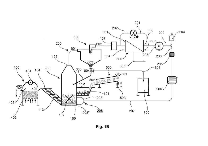
Fig. 1A is a schematic flow diagram illustrating a first embodiment of the
drying process in
accordance with the invention,
Fig. 1B is a schematic flow diagram illustrating similar to Fig. 1A, of a
second embodiment of the
drying process in accordance with the invention,
Fig. 2A is a schematic cross-section through the dis-aggregator in the drying
chamber,
Fig. 2B is a perspective view of the air supply device to the drying chamber,
Figs. 3A and 3B are perspective view through the condenser,
Fig. 4 is a perspective view of the box filter for removing fines, and
CA 03087364 2020-06-29
WO 2019/143254 PCT/N02019/050007
4
Fig. 5 is a perspective view of the honeycomb device for straightening air
flow to a heater.
Detailed description
Initially it should be mentioned that instrumentation, such as temperature
gauges, pressure gauges,
humidity gauges, flow meters and controller have been omitted for the case of
simplicity. However,
the person skilled in the art would be in a position of including the
instrumentation and controllers
necessary to operate the process.
Now referring to Fig. 1A, a simplified flow sheet a first embodiment of the
system in accordance
with the invention is shown. A dryer chamber housing is indicated by reference
numeral 100, having
an inlet 101 for waste material with a hopper which feeds a screw conveyor 112
that is time- and
flow-controlled to operate in semi-continuous or continuous mode. In a
preferred embodiment, a
feeder hopper 500 is arranged upstream of the drier chamber housing inlet 101,
having an inlet 501,
an outlet 502 in flow communication with the dryer housing inlet 101. The
feeder hopper is kept in
motion by an oscillator 503 to provide an initial de-clogging of the wet
material to be dried. In
Figures 1A and 1B, the feeder hopper 500 is illustrated as an elongate
rectangular duct, inclined in
a direction downward in flow direction toward the outlet 502, and with an
oscillator means arranged
at the inlet end 501 to oscillate the feeder hopper 500 up and down urging the
wet material toward
the outlet 502 and de-bridging possibly agglomerated feed.
A rotary impeller 102 is arranged at the bottom of the drying chamber housing
100, which serves to
disaggregate and circulate the waste material and, in combination with air
flow, establishing a
fluidized bed at the bottom of the drying chamber housing 100. A particle
separator, here provided
in the form of a main filter 103, arranged in the upper part of the drying,
covering the cross-section
of the dryer housing 100. A product outlet 104 is arranged at the bottom of
the drying chamber
housing 100, e.g. a screw conveyor 113, which is controlled to semi-
continuously or continuously
discharge dried material. A product cooler arranged downstream of the product
outlet 104 is
indicated by reference numeral 400, having an inlet 401 connected with a
drying chamber and an
outlet 402 for cooled product discharge. A grid 403 is arranged inside the
drying chamber, supplied
with cold air to cool dried-hot product located inside the cooling chamber.
Moreover, a fan 404 is
arranged to draw cooled air into grid 403 and through product in the cooler
housing 405. Then, the
fan 404 blows the warmer exiting air through the inlet feed that is pre-heated
and energy is
recovered.
The product cooler 400 is advantageously kept in motion by an oscillator (not
shown).The dryer
housing 100 further comprises a gas outlet 105 connected with gas duct 200. A
box filter 107 (Fig.
CA 03087364 2020-06-29
WO 2019/143254 PCT/N02019/050007
4) is arranged in gas duct 200, to remove and collect very fine particles down
to 30 microns or
smaller. The filter is described in more details below.
A condenser 300 is arranged downstream of the box filter 107, to condense
vapour and remove
liquid in air exhausted from the dryer chamber housing 100. Cooling water, at
a temperature at least
5 5 C lower than the dew point of the incoming condensing air stream,
enters the condenser 300 at
cooling water inlet 303, absorbs energy and increases its enthalpy and leaves
the condenser 300 at
cooling water outlet 304. Condensed liquid is drained at condense outlet 305
and from which the
condensate energy can be recovered to preheat the material, screw conveyors or
dis-integrator. A
bypass duct 201 is arranged in the gas duct 200, connecting the gas inlet 301
and gas outlet 302 of
the condenser 300. A bypass valve means 202 is arranged in the bypass duct
201, e.g. a flap or baffle
valve, for partial control of flow, humidity and quality. The flap valve is
opened in cases where the
gas flow contains little humidity, as to control humidity and dry air mixture
ratio and thus saving
energy in the process.
In a second embodiment, illustrated in Fig. 1B, the main filter 103 has been
replaced by a cyclone
600 having an inlet 601 for dust-containing air in flow connection with gas
duct 200 and outlet 105
of the dryer housing. The cyclone further exhibits a solids outlet 603 in the
bottom of the cyclone
housing in flow connection with a three-way valve 604 further connected to a
recycle duct 605 for
recycling fines back to drying chamber housing 100, and a fines duct 606
connected to a dry fines
container 700. Substantially clean air is ejected from the cyclone 600 through
clean air outlet 602
downstream of the box filter 107. The second embodiment with a dust collector
in the form of one
or more cyclones is preferred to the main filter embodiment because the
cyclone is practically
maintenance-free, contrary to dust filter which needs maintenance and
replacement. The cyclone
embodiment also has the advantages that the process can be operated fully
continuously.
Moreover, the cyclone embodiments operates at lower pressure drop, thus
reducing the operating
costs of the system.
A fan 203 is arranged in the gas duct, in this embodiment downstream of
condenser 300. A time-
controlled, electrically controlled or hydraulically controlled relief valve
bleeder 204 is arranged in
duct 200 downstream of fan 203, controlled by a pressure gauge and temperature
gauge. In this
way the excess vapour and non-condensable gases are removed from the drying
loop.
The duct further comprises a honeycomb structure 205 (Fig. 5), exhibiting
numerous adjacent flow
channels, arranged with the longitudinal axis substantially aligned with the
flow direction in duct
CA 03087364 2020-06-29
WO 2019/143254 PCT/N02019/050007
6
200 and upstream of a heater 206. The honeycomb structure 205 serves to make
the air flow
uniform and the air heating in heater 206 becomes more efficient.
Moreover, the heater 206 preferably comprises numerous elongate heating
elements, extending
with their longitudinal axis substantially perpendicular to the flow
direction. The heater is composed
of set of elements that are connected in parallel to each other as to release
energy either to heating
the material, heating the metal components and for moisture evaporation, or
individually such as
only for moisture evaporation. The heater is preferably operated by
electricity, but it can also use
steam recovered from other processes, such as discharge from turbines or from
evaporation
systems. The heater supplies energy to increase the air-steam temperature to
the required 70-140 C
at the inlet of dryer housing 100.
The gas duct 207 is downstream of heater 206 in a gas manifold 208 split into
a first gas return duct
208' and second gas return duct 208" and connected with gas return inlet 106
in dryer 100, as
explained in further details immediately below.
Fig. 2A illustrates a vertical cross-section of a part of the dryer, in this
embodiment, comprising a
first and second drying chambers 108' and 108", provided with first and second
impeller 102' and
102", respectively. An electric motor 109 is arranged at the drying chambers
to operate the
impellers 102' and 102". Recycled air is injected into the drying chambers
108' and 108" through a
first and second recycle gas inlet 106' and 106", respectively. The gas inlets
106' and 106" are
arranged in a side wall of the respective drying chambers 108' and 108",
arranged to inject drying
.. air in a direction substantially horizontally into the respective drying
chambers 108' and 108". This
horizontal injection of drying air provides, together with impeller 102,
formation and maintenance
of a fluidized bed in an efficient manner, enhancing heat transfer and
moisture removal capacity.
Fig. 2B illustrates a recycle gas inlets 106' and 106" in the form of a
recycle gas manifold 208
mentioned above in perspective, arranged to connect to an end of gas duct 207
and to first and
second recycle gas inlet 208' and 208".
Now referring to Figs. 3A and 3B, the condenser 300 is shown in perspective in
a partial cut-out,
comprising a housing 306 with a first and second gas inlet 301' and 301",
respectively, and a gas
outlet 302. Numerous lamellas and fins 307 are arranged in a traditional
manner, provided with
pipes 308 for cooling liquid. In accordance with the invention, numerous
baffle plates 309 are
arranged with one side or end attached to the internal wall of the housing 306
and the opposite side
or end ("free end") terminated at a distance from the internal wall of the
housing 306. Adjacent
baffle plates, arranged at a distance therefrom, are arranged with their free
end in an alternating
CA 03087364 2020-06-29
WO 2019/143254 PCT/N02019/050007
7
manner, thus forming a wave-shaped gas flow path through the condenser 300.
This arrangement
with several gas inlets 301' and 301" and baffled gas flow path by the baffle
plates 309 provides a
more efficient heat transfer and higher condensation than a traditional
condenser with one single
gas inlet and without baffle plates. Accordingly, the condenser can be built
with smaller dimensions
than prior art condensers.
Fig. 4 illustrates the box filter 107 comprising a box housing with a gas
inlet 110 and gas outlet 111,
and a frontal opening to accommodate an access window. A bag filter 113 is
arranged slidably
(arrow) inside the box filter housing 110 for easy and quick exchange by a new
filter when it has
reached its service life. The window is sealed, has an opening handle and 120
angular rotation
provided by two barrel hinges.
Finally, Fig. 5 illustrates the honeycomb device, comprising numerous elongate
cells 205' with open
ends and arranged adjacent to another in a housing (not shown) having a gas
inlet and gas outlet.
The honeycomb device is arranged with the elongate cells with their
longitudinal axis extending in
line with the flow direction in duct 200. As mentioned above, the honeycomb
device is useful for
providing a more efficient heating in the heater 206 because the gas flow
becomes more uniform
across the tube section, more stable and less wavy near the heater's wall.
Mode of operation
The principle of operation and method is explained by considering Figs. 1 and
2. The air enters the
dryer housing 100 and suspends the wet material together with the rotating
action of the dis-
aggregator or impeller 102. The material is contained in a hopper and is
continuously or semi-
continuously loaded by a flow and time controlled horizontal screw-conveyor
112 in the drying
chamber 100, 108', 108". The dried product is unloaded by an inclined a flow
controlled screw-
conveyor 113. As the suspended or fluidized material is heated by the air, it
is being dried, and vapor
or moisture is transported by the flowing air, crossing the main filter 103
that collects small dried
particles. After flowing through a smooth 90 bend, the air passes the quick-
release box filter that
collects and traps the remaining very fine particles, avoiding their further
transport to the next
process components. At this stage there are two ways for the air to flow,
which allows adjustment
of the temperature, relative humidity and quality of an air-steam. In the
normal way, the air-steam
flows through the condenser 300 where the vapor changes phase to liquid and is
drained out of the
drying loop in duct 200 at condenser outlet 305, from which energy is
recovered to pre-heat the
incoming material. In the other way air bypasses the condenser and flows
through the flap or baffle
valve 202. To perform this task, the condenser's fins or lamellas and
stainless steel tube surface
CA 03087364 2020-06-29
WO 2019/143254 PCT/N02019/050007
8
temperature is kept below the dew-point temperature of the incoming air-steam
mixture. Then, the
air enters the suction side of the fan 203 that provides the required
volumetric and mass flow rates
and pressure difference. The air enters a smooth bend where it flows in one of
two directions. One
direction is toward the time-controlled relief valve 204 and to a water lock
(not shown). In this way
the vapor and non-condensable gases are removed from the drying loop. Another
direction is
toward the honeycomb device 205, which is the normal flow of air. The
honeycomb device provides
uniform air-steam flow prior to enter the heater 206, which releases the
exactly amount of energy
as required to heat the mixture to the set conditions required for drying,
that is, temperature,
quality or relative humidity. Then, the air flows through a smooth bend and to
the downcomer 208,
whereupon it enters the curved two-expansions manifold 208, 208' and 208".
Finally, the air enters
the drying chamber 108', 108" to dry the suspended material and transport the
removed vapor,
thus repeating the cycle.
The process can be operated in numerous manners, e.g. batchwise, continuously
or semi-
continuously. These modes of operation are possible because the screw conveyor
112 is time and
flow controlled to feed the material batchwise, semi-continuously or
continuously into the drying
chamber.
Technical effects
The drying chambers with horizontal air injection combined with one or more
rotary impellers
serving as grinder, dis-integrator, circulators and mixer, ensure that the
material to be dried is kept
suspended, disaggregated or dispersed for proper drying. As a result, a large
material surface for
drying is obtained. Moreover, sticky material is prevented from clogging or
blocking the air flow
while keeping a stable suspended bed of material. This is a favourable
procedure because drying
with suspended bed reduces energy use, residence time and pressure loss.
The bypass duct around the condenser reduces energy consumption when the air
from the dryer
contains little humidity while adjusting the dry air and vapour ratio.
The condenser itself with numerous condensing gas inlets and staggered baffle
plates increases the
condenser efficiency and condensation capacity and allows for a more compact
design or higher
cooling effect compared to prior art condensers.
The honeycomb device provides uniform, stable and non-wavy air flow prior to
enter the heater,
which releases the exactly amount of energy as required to heat the mixture to
the set conditions
required for drying, that is, temperature, quality or relative humidity.
CA 03087364 2020-06-29
WO 2019/143254 PCT/N02019/050007
9
Modifications
While the invention has been described by air as drying medium, the process
can be operated by
steam as drying medium as well. In that case, the process will exhibit a
slightly different design with
similar layout of components. Alternatively, the process can be operated by
applying heat pump
with fluids with zero global warming potential and zero ozone depletion
potential. The dryer housing
has been illustrated with one or two drying chambers, but the invention can
comprise three or more
drying chambers and a hot product cooling chamber. The dryer is modular and
can accommodate
double, triple or quadruple sized drying chambers for multiple capacity or
volume of material to be
dried. The secondary filter 107 is not required, but is recommended in order
to keep fouling at a low
level and prevent clogging or blocking airflow in downstream components.