Note: Descriptions are shown in the official language in which they were submitted.
CA 03087848 2020-07-07
WO 2019/199281
PCT/US2018/026894
GAS-ENHANCED ELECTROSURGICAL GENERATOR
CROSS-REFERENCE TO RELATED APPLICATIONS
[00011 None.
STATEMENT REGARDING FEDERALLY
SPONSORED RESEARCH OR DEVELOPMENT
10002 None.
BACKGROUND OF THE INVENTION
Field Of The Invention
[00031 The present invention relates to gas-enhanced electrosurgical systems,
and more
particularly, to a gas control module for a gas-enhanced electrosurgical
system.
Brief Description Of The Related Art
10004j A variety of different electrosurgical generators are known. U.S.
Patent No.
4,429,694 to McGreevy disclosed an electrosurgical generator and argon plasma
system
and a variety of different electrosurgical effects that can be achieved
depending primarily
on the characteristics of the electrical energy delivered from the
electrosurgical generator.
The electrosurgical effects included pure cutting effect, a combined cutting
and
hemostasis effect, a fulguration effect and a desiccation effect. Fulguration
and
desiccation sometimes are referred to collectively as coagulation.
MOS] Another method of monopolar electrosurgery via argon plasma technology
was
described by Morrison in U.S. Patent No. 4,040,426 in 1977 and McGreevy U.S.
Patent
No. 4,781,175. This method, referred to as argon plasma coagulation (APC) or
argon
beam coagulation is a non-contact monopolar thermoablative method of
electrocoagulation that has been widely used in surgery for the last twenty
years. In
general, APC involves supplying an ionizable gas such as argon past the active
electrode
1
CA 03087848 2020-07-07
WO 2019/199281
PCT/US2018/026894
to target tissue and conducting electrical energy to the target tissue in
ionized pathways as
non-arcing diffuse current. Canady described in U.S. Patent No. 5,207,675 the
development of APC via a flexible catheter that allowed the use of APC in
endoscopy.
These new methods allowed the surgeon, endoscopist to combine standard
monopolar
electrocautery with a plasma gas for coagulation of tissue.
100061 Yet another system is disclosed in U.S. Patent Application Publication
No.
2013/0296846, which disclosed a system for simultaneously cutting and
coagulating
tissue. Another system, referred to as a "cold atmospheric plasma" system, is
disclosed
in U.S. Patent Application Publication No. 2014/0378892.
SUMMARY OF THE INVENTION
100(7 In a preferred embodiment, the present invention is a gas-enhanced
electrosurgical generator. The gas-enhanced generator has a housing, a first
gas control
module in the housing and configured to control flow of a first gas, a second
gas control
module in the housing and configured to control flow of a second gas, a high
frequency
power module, and a controller, processor or CPU within the housing and
configured to
control the first gas control module, the second gas control module and the
high
frequency power module. The gas-enhanced electrosurgical generator further may
have a
first connector secured on an exterior of the housing, wherein the first
connector
comprises a fluid connector connected to an output port of the first gas
control module,
and a second connector secured on an exterior of the housing, wherein the
second
connector comprises a fluid connector connected to an output port of the
second gas
control module and an electrical connector connected to an output of the high
frequency
power module. The first gas and second gas may be any of CO2, argon and helium
or
2
CA 03087848 2020-07-07
WO 2019/199281
PCT/US2018/026894
another gas. The gas-enhanced electrosurgical generator may have a third gas
control
module in the housing and configured to control flow of a third gas and a
third connector
secured on an exterior of the housing, wherein the third connector comprises a
fluid
connector connected to an output port of the third gas control module, and an
electrical
connector connected to an output of the high frequency power module. For
example, the
first gas comprises CO2, the second gas comprises argon and the third gas
comprises
helium.
10008j A gas-enhanced electrosurgical generator further may have a sub-system
for
controlling intraabdominal pressure in a patient. The sub-system for
controlling
intraabdominal pressure in a patient may have a 3-way proportional valve
connected to
an output port of the first gas control module, a pressure control valve
having an internal
pressure chamber, a port to the internal pressure chamber, an exhaust and an
exterior port
configured to release intraabdominal pressure from a patient, a first pressure
sensor for
sensing a pressure in the chamber, and a second pressure sensor connected to
the exterior
port. The gas-enhanced electrosurgical generator further may have a touch-
screen
display mounted to the housing. The generator further may have a graphical
user
interface, wherein the CPU is configured to control the graphical user
interface and the
touch-screen display.
[00091 In the gas-enhanced electrosurgical generator the HF power supply may
be
configured to supply high frequency energy to argon plasma coagulation
attachment and
supply low frequency electrosurgical energy to cold atmospheric plasma
attachment
based upon settings input through the touch screen.
3
CA 03087848 2020-07-07
WO 2019/199281
PCT/US2018/026894
1-00101 The first, second and third gas control module each may have the
following
structure. The gas control module has an inlet port, a first solenoid valve
connected to
the inlet port, the first solenoid valve being configured to turn a flow of
gas into the gas
control module on and off, a first pressure sensor configured to sense a first
pressure of
gas entering the gas control module through the first solenoid valve, a first
pressure
regulator configured to change the first pressure of gas entering the first
pressure
regulator to a second pressure, a first flow sensor configured to sense a flow
rate of gas
exiting the first pressure regulator, a first proportional valve having an
inlet and an outlet,
the first proportional valve being configured to adjust the outlet as a
percentage of the
inlet, a second flow sensor configured to sense a flow of gas exiting the
first proportional
valve, a second solenoid valve being a 3-way valve, a vent connected to the
second
solenoid valve, a second pressure sensor for sensing a pressure of gas passing
through the
second solenoid valve, and a third solenoid valve, the third solenoid valve
being
configured to turn a flow of gas out of the gas control module on and off, and
an exit
port. The second pressure may lower than the first pressure and the first
pressure
regulator reduces the first pressure to the second pressure. The first
pressure, for
example, may be 50-100 psi and the second pressure may be 15-20 psi. The gas
control
module for a gas-enhanced electrosurgical system according to claim 1 may
further have
tubing for connecting the exit port to an electrosurgical accessory. The gas
control
module further comprising a support structure for supporting at least two of
the first
solenoid valve , the first pressure sensor, the first pressure regulator, the
first flow sensor,
the second solenoid valve, the second flow sensor, the second solenoid valve,
the second
pressure sensor and the third solenoid valve. The support structure may
comprise a
4
CA 03087848 2020-07-07
WO 2019/199281
PCT/US2018/026894
frame, a housing or another support element and, for example, may be formed of
steel,
plastic or a combination of those.
[poi fl. Still other aspects, features, and advantages of the present
invention are readily
apparent from the following detailed description, simply by illustrating a
preferable
embodiments and implementations. The present invention is also capable of
other and
different embodiments and its several details can be modified in various
obvious respects,
all without departing from the spirit and scope of the present invention.
Accordingly, the
drawings and descriptions are to be regarded as illustrative in nature, and
not as
restrictive. Additional objects and advantages of the invention will be set
forth in part in
the description which follows and in part will be obvious from the
description, or may be
learned by practice of the invention.
BRIEF DESCRIPTION OF THE DRAWINGS
10012 For a more complete understanding of the present invention and the
advantages
thereof, reference is now made to the following description and the
accompanying
drawings, in which:
[001.1 FIG. 1A is a perspective view of a preferred embodiment of a gas-
enhanced
electrosurgical generator.
[00141 FIG. 1B is a front view of a preferred embodiment of a gas-enhanced
electrosurgical generator.
[0015I FIG. 1C is a rear view of a preferred embodiment of a gas-enhanced
electrosurgical generator.
CA 03087848 2020-07-07
WO 2019/199281
PCT/US2018/026894
[00161 FIG. 1D is a left side view of a preferred embodiment of a gas-enhanced
electrosurgical generator.
[00171 FIG. 1E is a right view of a preferred embodiment of a gas-enhanced
electrosurgical generator.
[001N FIG. 1F is a top view of a preferred embodiment of a gas-enhanced
electrosurgical generator.
[0019] FIG. 1G is a bottom view of a preferred embodiment of a gas-enhanced
electrosurgical generator.
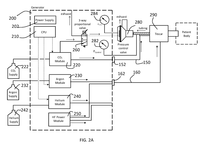
[0020 FIG. 2A is a block diagram of a preferred embodiment of a gas-enhanced
electrosurgical generator having a pressure control system in accordance with
the present
invention configured to perform an argon-enhanced electrosurgical procedure.
[OO2j FIG. 2B is a block diagram of a preferred embodiment of a gas-enhanced
electrosurgical generator having a pressure control system in accordance with
the present
invention configured to perform a cold atmospheric plasma procedure.
[0022] FIG. 2C is a diagram of a trocar for the embodiment of FIG. 2A in
accordance
with the present invention.
[002 FIG. 2D is a block diagram of an alternate preferred embodiment of
pressure
control system of a gas-enhanced electrosurgical generator having a pressure
control
system in accordance with the present invention configured to perform an argon-
enhanced electrosurgical procedure.
[00241 FIG. 3A is a schematic flow diagram illustrating the gas flow through
the module
and the method by which the module controls the gas flow in accordance with a
preferred
embodiment of the present invention.
6
CA 03087848 2020-07-07
WO 2019/199281
PCT/US2018/026894
[002fl FIG. 3B is a schematic flow diagram illustrating the gas flow through
an alternate
embodiment of the module and the method by which the module controls the gas
flow in
accordance with a preferred embodiment of the present invention.
[0026 FIG. 3C is a front view of a gas module in accordance with a preferred
embodiment of the present invention.
1.00271 FIG. 3D is a back view of a gas module in accordance with a preferred
embodiment of the present invention.
100281 FIG. 3E is a top view of a gas module in accordance with a preferred
embodiment
of the present invention.
[0029 FIG. 3F is a bottom view of a gas module in accordance with a preferred
embodiment of the present invention.
[00301 FIG. 3G is a first side view of a gas module in accordance with a
preferred
embodiment of the present invention.
1.003 FIG. 3H is a second side view of a gas module in accordance with a
preferred
embodiment of the present invention.
100321 FIG. 4A is a top view of a gas module within a housing or shield in
accordance
with a preferred embodiment of the present invention.
[0033 FIG. 4B is a side view of a gas module within a housing or shield in
accordance
with a preferred embodiment of the present invention.
[0034 FIG. 4C is a bottom view of a gas module within a housing or shield in
accordance with a preferred embodiment of the present invention.
1.00351 FIG. 5 is a diagram of a graphical user interface in accordance with a
preferred
embodiment of the present invention.
7
CA 03087848 2020-07-07
WO 2019/199281
PCT/US2018/026894
DETAILED DESCRIPTION OF THE PREFERRED EMBODIMENTS
[00361 The preferred embodiments of the inventions are described with
reference to the
drawings. A gas-enhanced electrosurgical generator 100 in accordance with a
preferred
embodiment of the present invention is shown in FIGs. 1A-1G. The gas-enhanced
generator has a housing 110 made of a sturdy material such as plastic or metal
similar to
materials used for housings of conventional electrosurgical generators. The
housing 110
has a removable cover 114. The housing 110 and cover 114 have means, such as
screws
119, tongue and groove, or other structure for removably securing the cover to
the
housing. The cover 114 may comprise just the top of the housing or multiple
sides, such
as the top, right side and left side, of the housing 110. The housing 110 may
have a
plurality of feet or legs 140 attached to the bottom of the housing. The
bottom 116 of the
housing 110 may have a plurality of vents 118 for venting from the interior of
the gas-
enhanced generator.
[00371 On the face 112 of the housing 114 there is a touch-screen display 120
and a
plurality of connectors 132, 134 for connecting various accessories to the
generator, such
as an argon plasma probe, a hybrid plasma probe, a cold atmospheric plasma
probe, or
any other electrosurgical attachment. There is a gas connector 136 for
connecting, for
example, a CO2 supply for insufflating an abdomen. The face 112 of the housing
110 is
at an angle other than 90 degrees with respect to the top and bottom of the
housing 110 to
provide for easier viewing and use of the touch screen display 120 by a user.
100381 One or more of the gas control modules may be mounting within a gas-
enhanced
electrosurgical generator 100. A gas pressure control system 200 for
controlling a
8
CA 03087848 2020-07-07
WO 2019/199281
PCT/US2018/026894
plurality of gas control modules 220, 230, 240 within a gas-enhanced
electrosurgical
generator is described with reference to FIGs. 2A-2D. A plurality of gas
supplies 222,
232, 242 are connected to the gas pressure control system 200, and more
specifically, to
the respective gas control modules 220, 230, 240 within the gas pressure
control system
200. The gas pressure control system 200 has a power supply 202 for supplying
power to
the various components of the system. A CPU 210 controls the gas pressure
control
modules 220, 230, 240 in accordance with settings or instructions entered into
the system
through a graphical user interface on the display 120. The system is shown
with gas
control modules for CO2, argon and helium, but the system is not limited to
those
particular gases. In the embodiment shown in FIGs. 2A-2D, the CO2 is shown as
the gas
used to insufflate an abdomen (or other area of a patient). The gas pressure
control
system 200 has a 3-way proportional valve connected to the gas control module
220.
While FIG.2A shows the 3-way proportional valve connected only to the CO2
control
module 220, the 3-way proportional valves could be connected to a different
gas control
module 230 or 240. The gas pressure control system 200 further has an HF power
module 250 for supplying high frequency electrical energy for various types of
electrosurgical procedures. The HF power module contains conventional
electronics
such as are known for provide HF power in electrosurgical generators.
Exemplary
systems include, but are not limited to, those disclosed in U.S. Patent No.
4,040,426 and
U.S. Patent No. 4,781,175. The system further could have a converter unit for
converting
the HF power to a lower frequency, such as may be used for cold atmospheric
plasma and
is described in U.S. Patent Application Publication No. 2015/0342663.
9
CA 03087848 2020-07-07
WO 2019/199281
PCT/US2018/026894
E00391 The outlet port of gas control module 220 is connected to a connector
136 on the
generator housing. While connector 136 and the other connectors are shown on
the front
face of the housing 110, they could be elsewhere on the housing. The outlet
ports of gas
control modules 230, 240 each are connected to tubing or other channel to a
connector
132. A connector 152 connects to connector 136 and is as tubing that runs to
and
connects to tubing 292. The tubing 292 is connected to a pressure control
valve or
stopcock 280 and extends into the trocar. The pressure control valve 280 is
used to
control pressure within the patient. The gas pressure control system further
has a
pressure sensor 282 connected to the tubing 292 to sense pressure in the
tubing 292 and a
pressure sensor 284 for sensing pressure in the pressure control valve 280. As
shown in
Fig. 2C, the tubing 292 is actually tube within a tube such that gas supplied
from the
generator travels to the trocar and patient through tube 296 and gas is
released out of the
patient through tube 294.
10040 As shown in FIG. 2A the connector 132 to which control module 230 is
connected has a gas-enhanced electrosurgical instrument 160 having a connector
162
connected to in. In FIG. 2A, gas control module 230 controls flow of argon
gas, so the
instrument 160 is an argon gas-enhanced electrosurgical tool such as an argon
plasma
probe such as is disclosed in U.S. Patent No. 5,720,745, a hybrid plasma cut
accessory
such as is disclosed in U.S. Patent Application Publication No. 2017/0312003
or U.S.
Patent Application Publication No. 2013/0296846, or a monopolar sealer such as
is
disclosed in U.S. Patent Application Publication No. 2016/0235462. Other types
of
argon surgical devices similarly can be used. As shown in FIG. 2B the
connector 132 to
which control module 240 is connected has a gas-enhanced electrosurgical
instrument
CA 03087848 2020-07-07
WO 2019/199281
PCT/US2018/026894
170 having a connector 172 connected to in. In FIG. 2B, gas control module 240
controls
flow of helium gas, so the instrument 170 is, for example, a cold atmospheric
plasma
attachment such as is disclosed in U.S. Patent Application Publication No.
2016/0095644.
[00411 The system provides for control of intraabdominal pressure in a
patient. The
pressure control valve 280 has a chamber within it. The pressure in that
chamber is
measured by pressure sensor 284. CO2 is supplied to the chamber within
pressure control
valve 280 from gas control module 220 via 3-way proportional valve 260.
Pressure in
that chamber within the pressure control valve 280 also may be released via 3-
way
proportional valve 260. In this manner, the system can use the pressure sensor
284 and
the 3-way proportional valve to achieve a desired pressure (set through a user
interface)
in the chamber within the pressure control valve 280. The pressure sensor 282
senses the
pressure in the tubing 294 (and hence the intraabdominal pressure). The
pressure control
valve 280 then releases pressure through its exhaust to synchronize the
intraabdominal
pressure read by sensor 282 with the pressure in the chamber within the
pressure control
valve as read by pressure sensor 284. The readings from sensors 282, 284 can
be
provided to CPU 210, which in turn can control flow of CO2 and one of argon
and
helium, depending on the procedure being performed, to achieve a stable
desired
intraabdominal pressure.
10042 An alternative embodiment of the gas pressure control system is shown in
FIG.
2D. This this system the automatic stopcock or pressure control valve 280 has
been
replaced by a manual relief valve 280a that is controlled or operated by the
surgeon using
the system.
11
CA 03087848 2020-07-07
WO 2019/199281
PCT/US2018/026894
E00431 A gas control module 300 in accordance with the present invention is
designed for
gas-enhanced electrosurgical systems. Conventionally, gas-enhanced
electrosurgical
systems have an electrosurgical generator and a gas control unit that have
separate
housings. The conventional gas control unit typically controls only a single
gas such as
argon, CO2 or helium. The present invention is a gas control module 300 that
may be
used in a gas control unit or in a combined unit functioning both as an
electrosurgical
generator and as a gas control unit. Further, a plurality of gas control
modules in
accordance with the present invention may be combined in a single gas control
unit or
combination generator/gas control unit to provide control of multiple gases
and provide
control for multiple types of gas-enhanced surgery such as argon gas
coagulation, hybrid
plasma electrosurgical systems and cold atmospheric plasma systems.
100441 FIG. 3A is a schematic flow diagram illustrating the gas flow through
the gas
control module 300 and the method by which the module 300 controls the gas
flow in
accordance with a preferred embodiment of the present invention. As shown in
FIG. 3A,
the gas enters the gas control module at an inlet port (IN) 301 and proceeds
to first
solenoid valve (SV1) 310, which is an on/off valve. In an exemplary
embodiment, the
gas enters the gas module at a pressure of 75 psi. The gas then proceeds to a
first
pressure sensor (P1) 320, to a first pressure regulator (R1) 330. In an
exemplary
embodiment, the first pressure regulator (R1) 330 reduces the pressor of the
gas from 75
psi to 18 psi. After the pressure regulator (R1) 330, the gas proceeds to flow
sensor
(FS1) 340, which sense the flow rate of the gas. Next, the gas proceeds to
proportional
valve (PV1) 350, which permits adjustment of a percentage of the opening in
the valve.
The gas then proceeds to a second flow sensor (FS2) 360, which senses the flow
rate of
12
CA 03087848 2020-07-07
WO 2019/199281
PCT/US2018/026894
the gas. This second flow sensor (FS2) 360 provides redundancy and thus
provides
greater safety and accuracy in the system. Next the gas proceeds to a second
solenoid
valve (SV2) 370, which is a three-way valve that provides for a vent function
that can
allow gas to exit the module through a vent 372. The gas then proceeds to a
second
pressure sensor (P2) 380, which provides a redundant pressure sensing function
that
against produces greater safety and accuracy of the system. Finally, the gas
proceeds to a
third solenoid valve (SV3) 390, which is a two-way on/off valve that is
normally closed
and is the final output valve in the module. The gas exits the module at and
output port
(OUT) 399, which is connected to tubing or other channel that provides a
passageway for
the gas to flow to an accessory connected to the electrosurgical unit.
[00461 FIG. 3B is a schematic flow diagram of an alternate embodiment of a gas
control
module illustrating the gas flow through the gas control module 300a and the
method by
which the module 300a controls the gas flow in accordance with a preferred
embodiment
of the present invention. As shown in FIG. 3B, the gas enters the gas control
module at
an inlet port 301a and proceeds to a first pressure regulator (R1) 330a. In an
exemplary
embodiment, the first pressure regulator (R1) 330a reduces the pressor of the
gas from
about 50-100 psi to 15-25 psi. After the pressure regulator (R1) 330a, the gas
proceeds to
a first pressure sensor (P1) 320a and then to a first solenoid valve (SV1)
310a, which is
an on/off valve. Next, the gas proceeds to proportional valve (PV1) 350a,
which permits
adjustment of a percentage of the opening in the valve. Next, the gas proceeds
to flow
sensor (FS1) 340a, which sense the flow rate of the gas. ext the gas proceeds
to a second
solenoid valve (SV2) 370a, which is a three-way valve that provides for a vent
function
that can allow gas to exit the module through a vent 372a. The gas then
proceeds to a
13
CA 03087848 2020-07-07
WO 2019/199281
PCT/US2018/026894
second flow sensor (F S2) 360a, which senses the flow rate of the gas. This
second flow
sensor (FS2) 360a provides redundancy and thus provides greater safety and
accuracy in
the system. The gas then proceeds to a second pressure sensor (P2) 380a, which
provides
a redundant pressure sensing function that against produces greater safety and
accuracy
of the system. The gas exits the module at and output port 399a, which is
connected to
tubing or other channel that provides a passageway for the gas to flow to an
accessory
connected to the electrosurgical unit.
100461 The various valves and sensors in either embodiment of the module are
electrically connected to a main PCB Board through a connector 490. The PCB
connector 490 is connected to a PCB Board that has a microcontroller (such as
CPU 210
in the embodiment shown in FIG. 2A). As previously noted, a plurality of gas
modules
can be in a single gas control unit or single electrosurgical generator to
provide control of
multiple differing gases. The plurality of gas control modules further may be
connected
to the same PCB Board, thus providing common control of the modules.
[WWI A gas control module of the embodiment of FIG. 3A is shown in further
detail in
FIGs. 3C-3H. The gas control module has a frame, housing or other support
structure
302. The various components forming the gas control modules are connected
directly or
indirectly to the frame, housing or other support structure 302. The frame,
housing or
other support member 302 may be formed, for example, from steel, plastic or
any other
material having sufficient strength to support the components of the module.
The frame,
housing, or other support member 302 may have a surface for receiving, for
example, a
manufacturer's label 304 or other identifying information.
14
CA 03087848 2020-07-07
WO 2019/199281
PCT/US2018/026894
E00481 As shown in FIG. 3C, the gas control module further has an outlet port
399, a
mass flow sensor (FS1) 340 and a pressure sensor assembly (P2) 380. The module
further may have, for example, a brass standoff 305. As shown in FIG. 3D, the
gas
control module further has a miniature medical regulator (R1) 330 and a mass
flow
sensor (FS2) 360. A vent 372 is connected to solenoid valve (SV2) 370. As
shown in
FIGs. 3C-3H the gas control module has a variety of stackable mounting
features 307,
309 and screw holes 311 for mounting the module in a housing. As shown in FIG.
3G,
the gas control module further has a solenoid vale (SV1) 310, which is an
on/off valve,
and a 2-way solenoid valve (SV3) 390. As shown in FIG. 3H, the module further
has a
solenoid valve (SV2) 370, a pressure sensor assembly (P1) 320 and a
proportional valve
(PV1) 350.
100491 FIGs. 4A-4C show a preferred embodiment of a gas control module with an
EMI
shield or housing on the module 410. The EMI shielding may be secured to the
module,
for example, with pan head screws inserted into screw holes 311. The EMI
shielding or
housing has stackable mounting features 452, 454. The EMI shielding or housing
further
may have a cable tie in push mount 430 and ferring ring 440 and zip ties 450
for securing
wires connected to the various components in the gas control module. The wires
are
connected to a main PCB connector 490.
[00501 All of the features of the housing, frame or other support structure
102, the EMI
shielding, the stacking features and mounting features similarly can be
incorporated in
the embodiment shown in FIG. 3B or in other embodiments of the invention.
100511 As shown in FIG. 5, the generator further may have graphical user
interface 500
for controlling the components of the system using the touch screen display
120. The
CA 03087848 2020-07-07
WO 2019/199281
PCT/US2018/026894
graphical user interface 500 for example, may control robotics 511, argon-
monopolar
cut/coag 512, hybrid plasma cut 513, cold atmospheric plasma 514, bipolar 515,
plasma
sealer 516, hemo dynamics 517 or voice activation 518. The graphical user
interface
further may be used with fluorescence-guided surgery 502. For example, J.
Elliott, et al.,
"Review of fluorescence guided surgery visualization and overlay techniques,"
BIOMEDICAL OPTICS EXPRESS 3765 (2015), outlines five practical suggestions for
display orientation, color map, transparency/alpha function, dynamic range
compression
and color perception check. Another example of a discussion of fluorescence-
guided
surgery is K. Tipirneni, et al., "Oncologic Procedures Amenable to
Fluorescence-guided
Surgery," Annals of Surgery, Vo. 266, No. 1, July 2017). The graphical user
interface
(GUI) further may be used with guided imaging such as CT, MM or ultrasound.
The
graphical user interface may communicate with RFID 520 (such as may be found
in
various electrosurgical attachments) and may collect and store usage data 530
in a storage
medium. The graphical user interface 500 communicates with FPGA 540, which may
control irrigation pump 552, insufflator 554, PFC 562, full bridge 564 for
adjusting the
power output, fly back 566 for regulating the power (DC to AC) and a foot
pedal 570.
[00521 The foregoing description of the preferred embodiment of the invention
has been
presented for purposes of illustration and description. It is not intended to
be exhaustive
or to limit the invention to the precise form disclosed, and modifications and
variations
are possible in light of the above teachings or may be acquired from practice
of the
invention. The embodiment was chosen and described in order to explain the
principles
of the invention and its practical application to enable one skilled in the
art to utilize the
invention in various embodiments as are suited to the particular use
contemplated. It is
16
CA 03087848 2020-07-07
WO 2019/199281
PCT/US2018/026894
intended that the scope of the invention be defined by the claims appended
hereto, and
their equivalents. The entirety of each of the aforementioned documents is
incorporated
by reference herein.
17