Note: Descriptions are shown in the official language in which they were submitted.
PROCESSES FOR PRODUCING OPTICAL EFFECTS LAYERS
FIELD OF THE INVENTION
[001] The present invention relates to the field of processes and printing
apparatuses for producing
optical effect layers (OELs) comprising magnetically oriented platelet-shaped
magnetic or magnetizable
pigment particles. In particular, the present invention provides processes and
printing apparatuses for
magnetically orienting platelet-shaped magnetic or magnetizable pigment
particles in coating layer so
as to produce OELs and the use of said OELs as anti-counterfeit means on
security documents or
security articles as well as decorative purposes.
BACKGROUND OF THE INVENTION
[002] It is known in the art to use inks, compositions, coatings or layers
containing oriented magnetic
or magnetizable pigment particles, particularly also optically variable
magnetic or magnetizable pigment
particles, for the production of security elements, e.g. in the field of
security documents. Coatings or
layers comprising oriented magnetic or magnetizable pigment particles are
disclosed for example in US
2,570,856; US 3,676,273; US 3,791,864; US 5,630,877 and US 5,364,689. Coatings
or layers
comprising oriented magnetic color-shifting pigment particles, resulting in
particularly appealing optical
effects, useful for the protection of security documents, have been disclosed
in WO 2002/090002 A2
and WO 2005/002866 Al.
[003] Security features, e.g. for security documents, can generally be
classified into "covert" security
features on the one hand, and "overt" security features on the other hand. The
protection provided by
covert security features relies on the principle that such features are
difficult to detect, typically requiring
specialized equipment and knowledge for detection, whereas "overt" security
features rely on the
concept of being easily detectable with the unaided human senses, e.g. such
features may be visible
and/or detectable via the tactile sense while still being difficult to produce
and/or to copy. However, the
effectiveness of overt security features depends to a great extent on their
easy recognition as a security
feature.
[004] Magnetic or magnetizable pigment particles in printing inks or coatings
allow for the production
of magnetically induced images, designs and/or patterns through the
application of a correspondingly
structured magnetic field, inducing a local orientation of the magnetic or
magnetizable pigment particles
in the not yet hardened (i.e. wet) coating, followed by the hardening of the
coating. The result is a fixed
and stable magnetically induced image, design or pattern. Materials and
technologies for the orientation
of magnetic or magnetizable pigment particles in coating compositions have
been disclosed for example
in US 2,418,479; US 2,570,856; US 3,791,864, DE 2006848-A, US 3,676,273, US
5,364,689, US
6,103,361, EP 0 406 667 BI; US 2002/0160194; US 2004/0009308; EP 0 710 508 Al;
WO 2002/09002
A2; WO 2003/000801 A2; WO 2005/002866 Al; WO 2006/061301 Al. In such a way,
magnetically
induced patterns which are highly resistant to counterfeit can be produced.
The security element in
question can only be produced by having access to both, the magnetic or
magnetizable pigment
particles or the corresponding ink, and the particular technology employed to
print said ink and to orient
said pigment in the printed ink.
[005] The methods and devices described hereabove use magnetic assemblies to
mono-axially orient
platelet-shaped magnetic pigment particles. Mono-axial orientation of magnetic
pigment particles result
1
Date Recue/Date Received 2023-06-07
in neighboring particles having their main axis parallel to each other and to
the magnetic field, while their
minor axis in the plane of the pigment particles is not, or much less
constrained by the applied magnetic
field.
[006] With the aim of producing coatings or layers comprising bi-axially
oriented magnetic or
magnetizable pigment particles, methods for generating time-dependent,
direction-variable magnetic
fields of sufficient intensity have been developed thus allowing the bis-axial
orientation of magnetic or
magnetizable pigment particles.
[007] WO 2015/086257 Al discloses an improved method for producing an optical
effect layer (OEL)
on a substrate, said process comprising two magnetic orientation steps, said
steps consisting of i)
exposing a coating composition comprising platelet-shaped magnetic or
magnetisable pigment particles
to a dynamic, i.e. direction changing, magnetic field of a first magnetic-
field-generating device so as to
bi-axially orient at least a part of the platelet-shaped magnetic or
magnetisable pigment particles and ii)
exposing the coating composition to a static magnetic field of a second
magnetic-field-generating device,
thereby mono-axially re-orienting at least a part of the platelet-shaped
magnetic or magnetisable
pigment particles according to a design transferred by said second magnetic-
field-generating device.
Whereas the method disclosed in WO 2015/086257 Al allows the production of
optical effects layers
exhibiting improved brightness and contrast compared to the prior art, said
process requires two
independent steps, wherein the first step requires additional space for the
pre-alignment of the magnetic
or magnetizable pigment particles. This requirement is cumbersome to be
implemented in a high-speed
industrial printing equipment since it requires additional space which is not
easily accessible on currently
printing equipments thus leading to the adaptation of the currently available
used equipments and high
costs.
[008] Therefore, a need remains for improved processes for producing optical
effect layers (OELs),
said methods being mechanically robust, easy to implement with an industrial
high-speed printing
equipment, in particular rotating magnetic orienting cylinders, without
resorting to cumbersome, tedious
and expensive modifications of said equipment. Said need remains especially
for improved process for
producing optical effect layers (OELs) displaying an eye-catching dynamic
effect, to provide, in
combination, a high resolution and a high contrast.
SUMMARY OF THE INVENTION
[009] Accordingly, it is an object of the present invention to overcome the
deficiencies of the prior art.
This is achieved by the provision of a process for producing an optical effect
layer (OEL) on a substrate
(x10), said process comprising the steps of:
a) applying onto a substrate (x10) surface a coating composition comprising
platelet-shaped magnetic
or magnetizable pigment particles so as to form a coating layer (x20) on said
substrate (x10), said
coating composition being in a first state,
b) placing the substrate (xl 0) carrying the coating layer (x20) on a first
magnetic-field-generating device
(x30) providing a first magnetic field vector component, said first magnetic-
field-generating device (x30)
being mounted on a transferring device (TD) thereby subjecting the platelet-
shaped magnetic or
magnetisable pigment particles to said first magnetic field vector component,
2
Date Recue/Date Received 2023-06-07
concomitantly moving said substrate (x10) carrying the coating layer (x20) and
said first magnetic-field-
generating device (x30) in the vicinity of a static second magnetic-field-
generating device (x40), said
second magnetic-field-generating device (x40) providing a second magnetic
field vector component
thereby subjecting the platelet-shaped magnetic or magnetisable pigment
particles to a time-dependent
resultant magnetic field formed by the first and second magnetic field vector
components so as to bi-
axially orient at least a part of the platelet-shaped magnetic or magnetizable
pigment particles,
wherein the ratio of the magnetic flux density of the first magnetic-field-
generating device (x30) and the
magnetic flux density of the second magnetic-field-generating device (x40) is
less than about 4.0,
preferably less than about 1.9 and more preferably between about 1.5 and about
0.5; and
c) hardening the coating composition to a second state so as to fix the
platelet-shaped magnetic or
magnetizable pigment particles in their adopted positions and orientations.
[010] Also described herein are optical effect layers (OELs) produced by the
process described herein
and security documents as well as decorative elements and objects comprising
one or more optical
OELs described herein.
[011] Also described herein are methods of manufacturing a security document
or a decorative
element or object, comprising a) providing a security document or a decorative
element or object, and
b) providing an optical effect layer such as those described herein, in
particular such as those obtained
by the process described herein, so that it is comprised in the security
document or decorative element
or object.
[012] Also described herein are printing apparatuses comprising the
transferring device (TD)
described herein, preferably the rotating magnetic cylinder (RMC) described
herein, and at least one of
the second magnetic-field-generating devices (x40) described herein, said
transferring device (TD),
preferably said rotating magnetic cylinder (RMC) comprising at least one of
the first magnetic-field-
generating devices (x30) described herein and mounted thereon.
[013] Also described herein are uses of the printing apparatuses for producing
the optical effect layers
(OELs) described herein.
[014] The process provided by the present invention is mechanically robust,
easy to implement with
an industrial high-speed printing equipment, without resorting to cumbersome,
tedious and expensive
modifications of said equipment.
BRIEF DESCRIPTION OF DRAWINGS
The optical effect layers (OEL) described herein and their production are now
described in more detail
with reference to the drawings and to particular embodiments, wherein
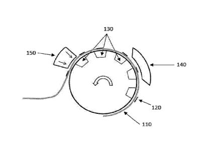
Fig. 1 schematically illustrates the exposure of a substrate (110) carrying a
coating layer (120) to i) a
first magnetic-field-generating device (130) being mounted on a transferring
device (TD), in particular a
rotating magnetic cylinder (RMC) and ii) a static second magnetic magnetic-
field-generating device
(140), where the substrate (110) carrying a coating layer (120) concomitantly
moves with the first
3
Date Recue/Date Received 2023-06-07
magnetic-field-generating device (130) in the vicinity of the static second
magnetic field generating
device (140). The coating layer (120) is hardened with a hardening unit (150)
so as to form an optical
effect layer (OEL).
Fig. 2 schematically illustrates a top view of a combination comprising a
first magnetic field generating
device (230) providing a first time-independent magnetic field vector
component and a static second
magnetic field generating device (240) providing a second magnetic field
vector component. The first
magnetic field generating device (230) being a bar dipole magnet which
synchronously and
concomitantly moves with a substrate (210) carrying a coating layer (220) (not
shown in Fig. 2) in the
vicinity of the second magnetic field generating device (240).
Fig. 3 schematically illustrates the magnetic fields of a first magnetic field
generating device (330)
providing a first time-independent magnetic field vector component (H1), the
magnetic fields of a second
magnetic field generating device (340) providing a second magnetic field
vector component (H2), and
the resultant magnetic field (H3) formed by the first and second magnetic
field vector components, i.e.
resulting from the vector addition of H1 and H2.
Fig. 4A schematically illustrates a process for the orientation of platelet-
shaped magnetic or
magnetizable pigment particles comprised in a coating layer (420) on a
substrate (410) using a
transferring device (TD), in particular a linear magnetic transferring device
(LMTD), according to the
present invention, said process comprising a step of concomitantly moving (see
grey arrow) the
substrate (410) carrying the coating layer (420) with a first magnetic-field-
generating device (430) in the
vicinity of a static second magnetic field generating device (440) comprising
two dipole bar magnets
(441a and 441b).
Fig. 4B schematically illustrates a cross-section of the first and second
magnetic-field-generating
devices (430, 440) of Fig. 4A. The bar dipole of the first magnetic-field-
generating device (430) is
comprised in a holder (431), wherein said holder is placed on top of a
supporting block (432) and a rail
(433). The two dipole bar magnets (441a and 441b) of the second magnetic-field-
generating device
(440) are inserted in two holders (442a and 442b) fixed on a frame (443a-c).
Fig. 4C schematically illustrates a cross-section of the first magnetic-field-
generating device (430) of
Fig. 4A-B. The first magnetic-field-generating device (430) is comprised in
the holder (431) supported
by the supporting block (432) and the rail (433) to be moveable in the
vicinity of the static second
magnetic-field-generating device, wherein the substrate (410) carrying the
coating layer (420) is placed
on top of said holder (431).
Fig. 5A-D schematically illustrates a top view (Fig. 5A and 5C) and a cross-
section (5B and 5D) of a
first magnetic field generating device (530) similar to the one depicted in
Fig. 4A-C and a Hall probe
(560) (Fig. 5A-5B) for measuring the magnetic flux density of the first
magnetic-field-generating device
.. (530) or a coating layer (520) on a substrate (510) (Fig. 5C-D).
Fig. 6A schematically illustrates schematically a second magnetic field
generating device (640) similar
to the one depicted in Fig. 4A-C and a Hall probe (660) (Fig. 6A) used for
measuring the magnetic flux
density of the second magnetic-field-generating device (640).
Fig. 6B-C schematically illustrate schematically a top view (Fig. 6B) and a
cross-section (6C) of a second
magnetic field generating device (640) similar to the one depicted in Fig. 4A-
C and a Hall probe (660)
4
Date Recue/Date Received 2023-06-07
used for measuring the magnetic flux density of the second magnetic-field-
generating device (640).
Fig. 7A schematically illustrates the working principles of conoscopic
scatterometry used to measure
the reflected beam directions in the OELs shown therein.
Fig. 7B schematically illustrates a complete reflection conoscopic
scatterometer setup, as used for
determining the orientation of pigment particles in the OEL.
Fig. 8 schematically illustrates a method of analysis of an OEL prepared with
an apparatus according
to the present invention with a conoscopic scatterometer.
Fig. 9A-D schematically illustrate the resulting reflected light spot on
the focal plane (960) (Fig. 9A
and 9B) and the distribution of azimuthal angles (Fig. 9C and 9D) of an OEL
made of oriented magnetic
or magnetizable pigment particles with a high degree of bi-axial alignment
(Fig. 9A and 9C) and of an
OEL made of oriented magnetic or magnetizable pigment particles with a low
degree of bi-axial
alignment (Fig. 9B and 9D) measurement principle of conoscopic scatterometry
used to analyze optical
effect layers (OEL) prepared with an apparatus.
DETAILED DESCRIPTION
Definitions
[015] The following definitions are to be used to interpret the meaning of the
terms discussed in the
description and recited in the claims.
[016] As used herein, the indefinite article "a" indicates one as well as more
than one and does not
necessarily limit its referent noun to the singular.
[017] As used herein, the term "at least" is meant to define one or more than
one, for example one or
two or three.
[018] As used herein, the term "about" means that the amount or value in
question may be the specific
value designated or some other value in its neighborhood. Generally, the term
"about" denoting a certain
value is intended to denote a range within 5% of the value. As one example,
the phrase "about 100"
denotes a range of 100 5, i.e. the range from 95 to 105. Generally, when the
term "about" is used, it
can be expected that similar results or effects according to the invention can
be obtained within a range
of 5% of the indicated value.
[019] As used herein, the term "and/or" means that either all or only one of
the elements of said group
may be present. For example, "A and/or B" shall mean "only A, or only B, or
both A and B". In the case
of "only A", the term also covers the possibility that B is absent, i.e. "only
A, but not B".
[020] The term "comprising" as used herein is intended to be non-exclusive and
open-ended. Thus,
for instance a coating composition comprising a compound A may include other
compounds besides A.
However, the term "comprising" also covers, as a particular embodiment
thereof, the more restrictive
meanings of "consisting essentially of' and "consisting of', so that for
instance "a coating composition
comprising A, B and optionally C" may also (essentially) consist of A and B,
or (essentially) consist of
A, B and C.
[021] The term "optical effect layer (OEL)" as used herein denotes a coating
or layer that comprises
oriented platelet-shaped magnetic or magnetizable pigment particles and a
binder, wherein said platelet-
shaped magnetic or magnetizable pigment particles are oriented by a magnetic
field and wherein the
5
Date Recue/Date Received 2023-06-07
oriented platelet-shaped magnetic or magnetizable pigment particles are
fixed/frozen in their orientation
and position (i.e. after hardening/curing) so as to form a magnetically
induced image.
[022] The term "coating composition" refers to any composition which is
capable of forming an optical
effect layer (EOL) on a solid substrate and which can be applied preferably
but not exclusively by a
printing method. The coating composition comprises the platelet-shaped
magnetic or magnetizable
pigment particles described herein and the binder described herein.
[023] As used herein, the term "wet" refers to a coating layer which is not
yet cured, for example a
coating in which the platelet-shaped magnetic or magnetizable pigment
particles are still able to change
their positions and orientations under the influence of external forces acting
upon them.
[024] As used herein, the term "indicia" shall mean discontinuous layers such
as patterns, including
without limitation symbols, alphanumeric symbols, motifs, letters, words,
numbers, logos and drawings.
[025] The term "hardening" is used to denote a process wherein the viscosity
of a coating composition
in a first physical state which is not yet hardened (i.e. wet) is increased so
as to convert it into a second
physical state, i.e. a hardened or solid state, where the platelet-shaped
magnetic or magnetizable pigment
particles are fixed/frozen in their current positions and orientations and can
no longer move nor rotate.
[026] The term "security document" refers to a document which is usually
protected against
counterfeit or fraud by at least one security feature. Examples of security
documents include without
limitation value documents and value commercial goods.
[027] The term "security feature" is used to denote an image, pattern or
graphic element that can be
used for authentication purposes.
[028] Where the present description refers to "preferred"
embodiments/features, combinations of
these "preferred" embodiments/features shall also be deemed as disclosed as
long as this combination
of "preferred" embodiments/features is technically meaningful.
[029] The present invention provides processes for producing optical effect
layers (OEL) on
substrates. The process according to the present invention comprises the steps
of:
a) applying onto the substrate (x10) surface described herein the coating
composition comprising
platelet-shaped magnetic or magnetizable pigment particles described herein so
as to form the coating
layer (x20) described herein on said substrate (x10), said coating composition
being in a first state,
b) placing the substrate (x10) carrying the coating layer (x20) on the first
magnetic-field-generating
device (x30) described herein and providing the first magnetic field vector
component described herein,
said first magnetic-field-generating device (x30) being mounted on a
transferring device (TD) thereby
subjecting the platelet-shaped magnetic or magnetisable pigment particles to
said first magnetic field
vector component,
concomitantly moving said substrate (x10) carrying the coating layer (x20) and
said first magnetic-field-
generating device (x30) in the vicinity of the static (i.e. not moving with
the transferring device (TD)),
second magnetic-field-generating device (x40) described herein, said second
magnetic-field-generating
device (x40) providing the second magnetic field vector component described
herein
6
Date Recue/Date Received 2023-06-07
thereby subjecting the platelet-shaped magnetic or magnetisable pigment
particles to the time-
dependent resultant magnetic field formed by the first and second magnetic
field vector components
described herein so as to bi-axially orient at least a part of the platelet-
shaped magnetic or magnetizable
pigment particles,
wherein the ratio of the magnetic flux density of the first magnetic-field-
generating device (x30) and the
magnetic flux density of the second magnetic-field-generating device (x40) is
less than about 4.0,
preferably less than about 1.9 and more preferably between about 1.5 and about
0.5, and
C) hardening the coating composition to a second state so as to fix the
platelet-shaped magnetic or
magnetizable pigment particles in their adopted positions and orientations.
[030] The present invention provides a reliable and easy to implement process
to produce optical
effect layers (OEL). The magnetic orientation of the platelet-shaped magnetic
or magnetizable pigment
particles on the substrate is carried out by placing the substrate (x10)
carrying the coating layer (x20)
comprising said platelet-shaped magnetic or magnetizable pigment particles on
the first magnetic-field-
generating device (x30) being mounted on the transferring device (TD)
described herein, preferably the
rotating magnetic cylinder (RMC) described herein, and submitting them to the
static second magnetic-
field-generating device, wherein the first magnetic-field-generating device
(x30) and the substrate (x10)
carrying the coating layer (x20) concomitantly move with the first magnetic-
field-generating device (x30)
and with the transferring device (TD) and wherein said second magnetic-field-
generating device is a
static device, i.e. does not move with the transferring device (TD).
[031] Since the substrate (x10) carrying the coating layer (x20) concomitantly
moves with the first
magnetic-field-generating device (x30), said first magnetic-field-generating
device (x30) providing a first
time-independent magnetic field vector component, the platelet-shaped magnetic
or magnetisable
pigment particles are subjected to said first magnetic field vector component,
wherein said first magnetic
field vector component is time-independent in the reference frame of the
coating layer, preferably time-
independent within a plane which is fixed in the reference frame of the
coating layer.
[032] The present invention takes advantage of the synchronous and concomitant
movement of the
substrate (x10) carrying the coating layer (x20) comprising platelet-shaped
magnetic or magnetizable
pigment particles with the first magnetic-field-generating device (x30) in the
vicinity of the static second
magnetic-field-generating device (x40), (i.e. through the magnetic field of
the static second magnetic-
field-generating device (x40), wherein said second magnetic-field-generating
device (x40) does not
move with the transferring device (TD) and provides a second magnetic field
vector component. The
resultant magnetic field formed by the first and second magnetic field vector
components allow the bi-
axial orientation of at least a part of the platelet-shaped magnetic or
magnetizable pigment particles.
During the process described herein, the platelet-shaped magnetic or
magnetizable pigment particles
are subjected to the time-dependent resulting magnetic field that is the
vector sum of the first and second
magnetic field vector components and move within said inhomogeneous resulting
magnetic field. By
"time-dependent magnetic field" it is meant that along the path of motion
followed by individual platelet-
shaped magnetic or magnetizable pigment particles of the coating layer, the
magnetic field is time
dependent (i.e. time-varying) in direction or time dependent (i.e. time-
varying) in direction and intensity
7
Date Recue/Date Received 2023-06-07
in the reference frame of the coating layer, preferably time-dependent (i.e.
time-varying) within a plane
which is fixed in the reference frame of the coating layer. In this way, at
least a part of the platelet-
shaped magnetic or magnetizable pigment particles of the coating layer tend to
align, resulting in a bi-
axial orientation of at least a part of said platelet-shaped magnetic or
magnetizable particles, i.e. an
orientation in which the two largest principal axes of said platelet-shaped
pigment particles are
constrained. Once the desired effect is created in the not yet hardened (i.e.
wet) coating layer, the
coating composition is partly or completely hardened so as to permanently
fix/freeze the relative position
and orientation of the platelet-shaped magnetic or magnetizable pigment
particles in the OEL.
[033] The transferring device (TD) described herein may be a rotating magnetic
orienting cylinder
(RMC) or a linear magnetic transferring device (LMTD) such as for example a
linear guide. Preferably,
the transferring device (TD) described herein is a rotating magnetic orienting
cylinder (RMC).
[034] As shown in Fig. 1, the first magnetic-field-generating device (x30)
described herein is mounted
on a transferring device (TD) being a rotating magnetic orienting cylinder
(RMC) described herein,
wherein said rotating magnetic orienting cylinder (RMC) is part of a rotary,
sheet-fed or web-fed
industrial printing press that operates at high printing speed in a continuous
way, in particular the first
magnetic-field-generating device (x30) is mounted on circumferential grooves
or transverse grooves of
the rotating magnetic cylinder (RMC). The rotating magnetic orienting cylinder
(RMC) comprising the
first magnetic-field-generating device (x30) described herein is aimed to be
used in, or in conjunction
with, or being part of a printing or coating equipment comprising the static
second magnetic-field-
generating device (x40) described herein so as to orient platelet-shaped
magnetic or magnetizable
pigment particles in the coating layer.
[035] The process described herein comprises a step a) of applying onto the
substrate (x10) surface
described herein the coating composition comprising platelet-shaped magnetic
or magnetizable pigment
particles described herein so as to form a coating layer (x20), said coating
composition being in a first
physical state which allows its application as a layer and which is in a not
yet hardened (i.e. wet) state
wherein the platelet-shaped magnetic or magnetizable pigment particles can
move and rotate within the
binder material. Since the coating composition described herein is to be
provided on a substrate (x10)
surface, the coating composition comprises at least a binder material such as
those described herein
and the platelet-shaped magnetic or magnetizable pigment particles, wherein
said coating composition
is in a form that allows its processing on the desired printing or coating
equipment. Preferably, said step
a) is carried out by a printing process, preferably selected from the group
consisting of screen printing,
rotogravure printing, flexography printing, inkjet printing and intaglio
printing (also referred in the art as
engraved copper plate printing and engraved steel die printing), more
preferably selected from the group
consisting of intaglio printing, screen printing, rotogravure printing and
flexography printing and still more
preferably selected from the group consisting of intaglio printing, screen
printing, rotogravure printing
and flexography printing.
[036] Screen printing (also referred in the art as silkscreen printing) is a
stencil process wherein an
ink is transferred to a surface through a stencil supported by a fine fabric
mesh of silk, mono- or multi-
filaments made of synthetic fibers such as for example polyamides or
polyesters or metal threads
8
Date Recue/Date Received 2023-06-07
stretched tightly on a frame made for example of wood or a metal (e.g.
aluminum or stainless steel).
Alternatively, the screen-printing mesh may be a chemically etched, a laser-
etched, or a galvanically
formed porous metal foil, e.g. a stainless steel foil. The pores of the mesh
are blocked in the non-image
areas and left open in the image area, the image carrier being called the
screen. Screen printing might
be of the flat-bed or rotary type. Screen printing is further described for
example in The Printing ink
manual, R.H. Leach and R.J. Pierce, Springer Edition, 5th Edition, pages 58-62
and in Printing
Technology, J.M. Adams and P.A. Dolin, Delmar Thomson Learning, 5th Edition,
pages 293-328.
1037] Rotogravure (also referred in the art as gravure) is a printing process
wherein the image
elements are engraved into the surface of a cylinder. The non-image areas are
at a constant original
level. Prior to printing, the entire printing plate (non-printing and printing
elements) is inked and flooded
with ink. Ink is removed from the non-image by a wiper or a blade before
printing, so that ink remains
only in the cells. The image is transferred from the cells to the substrate by
a pressure typically in the
range of 2 to 4 bars and by the adhesive forces between the substrate and the
ink. The term rotogravure
does not encompass intaglio printing processes (also referred in the art as
engraved steel die or copper
plate printing processes) which rely for example on a different type of ink.
More details are provided in
"Handbook of print media", Helmut Kipphan, Springer Edition, page 48 and in
The Printing ink manual,
R.H. Leach and R.J. Pierce, Springer Edition, 5th Edition, pages 42-51.
1038] Flexography preferably uses a unit with a doctor blade, preferably a
chambered doctor blade,
an anilox roller and plate cylinder. The anilox roller advantageously has
small cells whose volume and/or
density determines the ink application rate. The doctor blade lies against the
anilox roller, and scraps
off surplus ink at the same time. The anilox roller transfers the ink to the
plate cylinder which finally
transfers the ink to the substrate. Specific design might be achieved using a
designed photopolymer
plate. Plate cylinders can be made from polymeric or elastomeric materials.
Polymers are mainly used
as photopolymer in plates and sometimes as a seamless coating on a sleeve.
Photopolymer plates are
made from light-sensitive polymers that are hardened by ultraviolet (UV)
light. Photopolymer plates are
cut to the required size and placed in an UV fight exposure unit. One side of
the plate is completely
exposed to UV light to harden or cure the base of the plate. The plate is then
turned over, a negative of
the job is mounted over the uncured side and the plate is further exposed to
UV light. This hardens the
plate in the image areas. The plate is then processed to remove the unhardened
photopolymer from the
nonimage areas, which lowers the plate surface in these nonimage areas. After
processing, the plate is
dried and given a post-exposure dose of UV light to cure the whole plate.
Preparation of plate cylinders
for flexography is described in Printing Technology, J. M. Adams and P.A.
Dolin, Delmar Thomson
Learning, 5th Edition, pages 359-360 and in The Printing ink manual, R.H.
Leach and R.J. Pierce,
Springer Edition, 5th Edition, pages 33-42.
1039] The coating composition described herein as well as the coating layer
(x20) described herein
comprise platelet-shaped magnetic or magnetizable pigment particles.
Preferably, the platelet-shaped
magnetic or magnetizable pigment particles described herein are present in an
amount from about 5
wt-% to about 40 wt-%, more preferably about 10 wt-% to about 30 wt-%, the
weight percentages being
based on the total weight of the coating composition.
[040] In contrast to needle-shaped pigment particles which can be considered
as quasi one-
9
Date Recue/Date Received 2023-06-07
dimensional particles, platelet-shaped pigment particles are quasi two-
dimensional particles due to the
large aspect ratio of their dimensions. Platelet-shaped pigment particle can
be considered as a two-
dimensional structure wherein the dimensions X and Y are substantially larger
than the dimension Z.
Platelet-shaped pigment particles are also referred in the art as oblate
particles or flakes. Such pigment
particles may be described with a main axis X corresponding to their longest
dimension crossing the
pigment particle and a second axis Y perpendicular to X and crossing the
pigment particle. In other
words, the XY plane roughly defines the plane formed by the first and second
longest dimensions of the
pigment particle, the Z dimension being ignored.
[041] The platelet-shaped magnetic or magnetizable pigment particles described
herein have, due to
their non-spherical shape, non-isotropic reflectivity with respect to incident
electromagnetic radiation for
which the hardened/cured binder material is at least partially transparent. As
used herein, the term "non-
isotropic reflectivity" denotes that the proportion of incident radiation from
a first angle that is reflected
by a particle into a certain (viewing) direction (a second angle) is a
function of the orientation of the
particles, i.e. that a change of the orientation of the particle with respect
to the first angle can lead to a
different magnitude of the reflection to the viewing direction.
[042] The OEL described herein comprises platelet-shaped magnetic or
magnetizable pigment
particles that, due to their shape, have non-isotropic reflectivity. In the
OELs described herein, the
platelet-shaped magnetic or magnetizable pigment particles described herein
are dispersed in the
coating composition comprising a hardened binder material that fixes the
orientation of the platelet-
shaped magnetic or magnetizable pigment particles. The binder material is at
least in its hardened or
solid state (also referred to as second state herein), at least partially
transparent to electromagnetic
radiation of a range of wavelengths comprised between 200 nm and 2500 nm, i.e.
within the wavelength
range which is typically referred to as the "optical spectrum" and which
comprises infrared, visible and
UV portions of the electromagnetic spectrum. Accordingly, the particles
contained in the binder material
in its hardened or solid state and their orientation-dependent reflectivity
can be perceived through the
binder material at some wavelengths within this range. Preferably, the
hardened binder material is at
least partially transparent to electromagnetic radiation of a range of
wavelengths comprised between
200 nm and 800 nm, more preferably comprised between 400 nm and 700 nm.
Herein, the term
"transparent" denotes that the transmission of electromagnetic radiation
through a layer of 20 pm of the
hardened binder material as present in the OEL (not including the platelet-
shaped magnetic or
magnetizable pigment particles, but all other optional components of the OEL
in case such components
are present) is at least 50%, more preferably at least 60 %, even more
preferably at least 70%, at the
wavelength(s) concerned. This can be determined for example by measuring the
transmittance of a test
piece of the hardened binder material (not including the platelet-shaped
magnetic or magnetizable
pigment particles) in accordance with well-established test methods, e.g. DIN
5036-3 (1979-11). If the
OEL serves as a covert security feature, then typically technical means will
be necessary to detect the
(complete) optical effect generated by the OEL under respective illuminating
conditions comprising the
selected non-visible wavelength; said detection requiring that the wavelength
of incident radiation is
selected outside the visible range, e.g. in the near UV-range.
Date Recue/Date Received 2023-06-07
[043] Suitable examples of platelet-shaped magnetic or magnetizable pigment
particles described
herein include without limitation pigment particles comprising a magnetic
metal selected from the group
consisting of cobalt (Co), iron (Fe), and nickel (Ni); a magnetic alloy of
iron, manganese, cobalt, nickel
or a mixture of two or more thereof; a magnetic oxide of chromium, manganese,
cobalt, iron, nickel or a
.. mixture of two or more thereof; or a mixture of two or more thereof. The
term "magnetic" in reference to
the metals, alloys and oxides is directed to ferromagnetic or ferrimagnetic
metals, alloys and oxides.
Magnetic oxides of chromium, manganese, cobalt, iron, nickel or a mixture of
two or more thereof may
be pure or mixed oxides. Examples of magnetic oxides include without
limitation iron oxides such as
hematite (Fe203), magnetite (Fe304), chromium dioxide (Cr02), magnetic
ferrites (MFe204), magnetic
spinels (MR204), magnetic hexaferrites (MFe12019), magnetic orthoferrites
(RFe03), magnetic garnets
M3R2(A04)3, wherein M stands for two-valent metal, R stands for three-valent
metal, and A stands for
four-valent metal.
[044] Examples of platelet-shaped magnetic or magnetizable pigment particles
described herein
include without limitation pigment particles comprising a magnetic layer M
made from one or more of a
magnetic metal such as cobalt (Co), iron (Fe), or nickel (Ni); and a magnetic
alloy of iron, cobalt or
nickel, wherein said magnetic or magnetizable pigment particles may be
muttilayered structures
comprising one or more additional layers. Preferably, the one or more
additional layers are layers A
independently made from one or more selected from the group consisting of
metal fluorides such as
magnesium fluoride (Mg F2), silicium oxide (Si0), silicium dioxide (Si02),
titanium oxide (Ti02), and
aluminum oxide (A1203), more preferably silicium dioxide (Si02); or layers B
independently made from
one or more selected from the group consisting of metals and metal alloys,
preferably selected from the
group consisting of reflective metals and reflective metal alloys, and more
preferably selected from the
group consisting of aluminum (Al), chromium (Cr), and nickel (Ni), and still
more preferably aluminum
(Al); or a combination of one or more layers A such as those described
hereabove and one or more
layers B such as those described hereabove. Typical examples of the platelet-
shaped magnetic or
magnetizable pigment particles being multilayered structures described
hereabove include without
limitation AIM multilayer structures, A/M/A multilayer structures, A/M/B
multilayer structures, A/B/M/A
multilayer structures, A/B/M/B multilayer structures, A/B/M/B/A/multilayer
structures, BIM multilayer
structures, B/M/B multilayer structures, B/A/M/A multilayer structures, B/NM/B
multilayer structures,
.. B/A/M/B/A/multilayer structures, wherein the layers A, the magnetic layers
M and the layers B are
chosen from those described hereabove.
[045] The coating composition described herein may comprise platelet-shaped
optically variable
magnetic or magnetizable pigment particles, and/or platelet-shaped magnetic or
magnetizable pigment
particles having no optically variable properties. Preferably, at least a part
of the platelet-shaped
magnetic or magnetizable pigment particles described herein is constituted by
platelet-shaped optically
variable magnetic or magnetizable pigment particles. In addition to the overt
security provided by the
colorshifting property of the optically variable magnetic or magnetizable
pigment particles, which allows
easily detecting, recognizing and/or discriminating an article or security
document carrying an ink,
coating composition, or coating layer comprising the optically variable
magnetic or magnetizable
pigment particles described herein from their possible counterfeits using the
unaided human senses,
11
Date Recue/Date Received 2023-06-07
the optical properties of the optically variable magnetic or magnetizable
pigment particles may also be
used as a machine readable tool for the recognition of the OEL. Thus, the
optical properties of the
optically variable magnetic or magnetizable pigment particles may
simultaneously be used as a covert
or semi-covert security feature in an authentication process wherein the
optical (e.g. spectral) properties
of the pigment particles are analyzed.
[046] The use of platelet-shaped optically variable magnetic or magnetizable
pigment particles in
coating layers for producing an OEL enhances the significance of the OEL as a
security feature in
security document applications, because such materials are reserved to the
security document printing
industry and are not commercially available to the public.
[047] As mentioned above, preferably at least a part of the platelet-shaped
magnetic or magnetizable
pigment particles is constituted by platelet-shaped optically variable
magnetic or magnetizable pigment
particles. These are more preferably selected from the group consisting of
magnetic thin-film
interference pigment particles, magnetic cholesteric liquid crystal pigment
particles, interference coated
pigment particles comprising a magnetic material and mixtures of two or more
thereof.
[048] Magnetic thin film interference pigment particles are known to those
skilled in the art and are
disclosed e.g. in US 4,838,648; WO 2002/073250 A2; EP 0 686 675 BI; WO
2003/000801 A2; US
6,838,166; WO 2007/131833 Al; EP 2 402 401 Al and in the documents cited
therein. Preferably, the
magnetic thin film interference pigment particles comprise pigment particles
having a five-layer Fabry-
Perot multilayer structure and/or pigment particles having a six-layer Fabry-
Perot multilayer structure
and/or pigment particles having a seven-layer Fabry-Perot multilayer
structure.
[049] Preferred five-layer Fabry-Perot multilayer
structures consist of
absorber/dielectric/reflector/dielectric/absorber multilayer structures
wherein the reflector and/or the
absorber is also a magnetic layer, preferably the reflector and/or the
absorber is a magnetic layer
comprising nickel, iron and/or cobalt, and/or a magnetic alloy comprising
nickel, iron and/or cobalt and/or
a magnetic oxide comprising nickel (Ni), iron (Fe) and/or cobalt (Co).
[050] Preferred six-layer Fabry-Perot multilayer
structures consist of
absorber/dielectric/reflector/magnetic/dielectric/absorber multilayer
structures.
[051] Preferred seven-layer Fabry Perot multilayer structures consist of
absorber/dielectric/reflector/magnetic/reflector/dielectric/absorber
multilayer structures such as
disclosed in US 4,838,648.
[052] Preferably, the reflector layers described herein are independently made
from one or more
selected from the group consisting of metals and metal alloys, preferably
selected from the group
consisting of reflective metals and reflective metal alloys, more preferably
selected from the group
consisting of aluminum (Al), silver (Ag), copper (Cu), gold (Au), platinum
(Pt), tin (Sn), titanium (Ti),
palladium (Pd), rhodium (Rh), niobium (Nb), chromium (Cr), nickel (Ni), and
alloys thereof, even more
preferably selected from the group consisting of aluminum (Al), chromium (Cr),
nickel (Ni) and alloys
thereof, and still more preferably aluminum (Al). Preferably, the dielectric
layers are independently made
from one or more selected from the group consisting of metal fluorides such as
magnesium fluoride
(MgF2), aluminum fluoride (AIF3), cerium fluoride (CeF3), lanthanum fluoride
(LaF3), sodium aluminum
fluorides (e.g. Na3AIF6), neodymium fluoride (NdF3), samarium fluoride (SmF3),
barium fluoride (BaF2),
12
Date Recue/Date Received 2023-06-07
calcium fluoride (CaF2), lithium fluoride (LiF), and metal oxides such as
silicium oxide (Si0), silicium
dioxide (SiO2), titanium oxide (h02), aluminum oxide (Al2O3), more preferably
selected from the group
consisting of magnesium fluoride (MgF2) and silicium dioxide (SiO2) and still
more preferably magnesium
fluoride (MgF2). Preferably, the absorber layers are independently made from
one or more selected from
the group consisting of aluminum (Al), silver (Ag), copper (Cu), palladium
(Pd), platinum (Pt), titanium
(Ti), vanadium (V), iron (Fe) tin (Sn), tungsten (W), molybdenum (Mo), rhodium
(Rh), Niobium (Nb),
chromium (Cr), nickel (Ni), metal oxides thereof, metal sulfides thereof,
metal carbides thereof, and
metal alloys thereof, more preferably selected from the group consisting of
chromium (Cr), nickel (Ni),
metal oxides thereof, and metal alloys thereof, and still more preferably
selected from the group
consisting of chromium (Cr), nickel (Ni), and metal alloys thereof.
Preferably, the magnetic layer
comprises nickel (Ni), iron (Fe) and/or cobalt (Co); and/or a magnetic alloy
comprising nickel (Ni), iron
(Fe) and/or cobalt (Co); and/or a magnetic oxide comprising nickel (Ni), iron
(Fe) and/or cobalt (Co).
When magnetic thin film interference pigment particles comprising a seven-
layer Fabry-Perot structure
are preferred, it is particularly preferred that the magnetic thin film
interference pigment particles
comprise a seven-layer Fabry-Perot absorber/dielectric/reflector/mag
netic/reflector/dielectric/absorber
multilayer structure consisting of a Cr/MgF2/Al/Ni/Al/MgF2/Cr multilayer
structure.
[053] The magnetic thin film interference pigment particles described herein
may be multilayer
pigment particles being considered as safe for human health and the
environment and being based for
example on five-layer Fabry-Perot multilayer structures, six-layer Fabry-Perot
multilayer structures and
seven-layer Fabry-Perot multilayer structures, wherein said pigment particles
include one or more
magnetic layers comprising a magnetic alloy having a substantially nickel-free
composition including
about 40 wt-% to about 90 wt-% iron, about 10 wt-% to about 50 wt-% chromium
and about 0 wt-% to
about 30 wt-% aluminum. Typical examples of multilayer pigment particles being
considered as safe for
human health and the environment can be found in EP 2 402 401 Al.
[054] Magnetic thin film interference pigment particles described herein are
typically manufactured by
a conventional deposition technique of the different required layers onto a
web. After deposition of the
desired number of layers, e.g. by physical vapor deposition (PVD), chemical
vapor deposition (CVD) or
electrolytic deposition, the stack of layers is removed from the web, either
by dissolving a release layer
in a suitable solvent, or by stripping the material from the web. The so-
obtained material is then broken
down to flakes which have to be further processed by grinding, milling (such
as for example jet milling
processes) or any suitable method so as to obtain pigment particles of the
required size. The resulting
product consists of flat flakes with broken edges, irregular shapes and
different aspect ratios. Further
information on the preparation of suitable magnetic thin film interference
pigment particles can be found
e.g. in EP 1 710 756 Al and EP 1 666 546 Al.
[055] Suitable magnetic cholesteric liquid crystal pigment particles
exhibiting optically variable
characteristics include without limitation magnetic monolayered cholesteric
liquid crystal pigment
particles and magnetic multilayered cholesteric liquid crystal pigment
particles. Such pigment particles
are disclosed for example in WO 2006/063926 Al, US 6,582,781 and US 6,531,221.
WO 2006/063926
Al discloses monolayers and pigment particles obtained therefrom with high
brilliance and colorshifting
properties with additional particular properties such as magnetizability. The
disclosed monolayers and
13
Date Recue/Date Received 2023-06-07
pigment particles, which are obtained therefrom by comminuting said
monolayers, include a three-
dimensionally crosslinked cholesteric liquid crystal mixture and magnetic
nanoparticles. US 6,582,781
and US 6,410,130 disclose platelet-shaped cholesteric multilayer pigment
particles which comprise the
sequence Al/B/A2, wherein A1 and A2 may be identical or different and each
comprises at least one
cholesteric layer, and B is an interlayer absorbing all or some of the light
transmitted by the layers AI
and A2 and imparting magnetic properties to said interlayer. US 6,531,221
discloses platelet-shaped
cholesteric multilayer pigment particles which comprise the sequence A/B and
optionally C, wherein A
and C are absorbing layers comprising pigment particles imparting magnetic
properties, and B is a
cholesteric layer.
[056] Suitable interference coated pigments comprising one or more magnetic
materials include
without limitation structures consisting of a substrate selected from the
group consisting of a core coated
with one or more layers, wherein at least one of the core or the one or more
layers have magnetic
properties. For example, suitable interference coated pigments comprise a core
made of a magnetic
material such as those described hereabove, said core being coated with one or
more layers made of
one or more metal oxides, or they have a structure consisting of a core made
of synthetic or natural
micas, layered silicates (e.g. talc, kaolin and sericite), glasses (e.g.
borosilicates), silicium dioxides
(SiO2), aluminum oxides (A1203), titanium oxides (h02), graphites and mixtures
of two or more thereof.
Furthermore, one or more additional layers such as coloring layers may be
present.
The magnetic or magnetizable pigment particles described herein may be surface
treated so as to
protect them against any deterioration that may occur in the coating
composition and coating layer
and/or to facilitate their incorporation in said coating composition and
coating layer; typically corrosion
inhibitor materials and/or wetting agents may be used.
[057] Further, subsequently to the application of the coating composition
described herein on the
substrate surface described herein so as to form a coating layer (step a)),
the substrate carrying the
coating layer is arranged on top of the first magnetic-field-generating device
(x30) being mounted on the
transferring device (TD) described herein, preferably on the rotating magnetic
cylinder (RMC) described
herein. The substrate (x10) carrying the coating layer (x20) may be directly
arranged on top of the first
magnetic-field-generating device (x30), i.e. the substrate is in direct
contact with the first magnetic-field-
generating device (x30) or a gap may be present between the substrate (x10)
and the first magnetic-
field-generating device (x30).
[058] According to one embodiment and as shown in Fig. 4A-C, the substrate
(x10) carrying the
coating layer (x20) is arranged on top of the first magnetic-field-generating
device (x30) with a gap
between the substrate (x10) and the first magnetic-field-generating device
(x30), wherein said gap may
be obtained by using one or more holders, one or more plates or one or more
spacers (x31). The holder,
the plate or the one or more spacers (x31) is/are independently preferably
made from one or more non-
magnetic materials selected from the group consisting of low conducting
materials, non-conducting
materials and mixtures thereof, such as for example engineering plastics and
polymers, titanium,
titanium alloys and austenitic steels (i.e. non-magnetic steels). Engineering
plastics and polymers
include without limitation polyaryletherketones (PAEK) and its derivatives
polyetheretherketones
(PEEK), poletherketoneketones (PEKK), polyetheretherketoneketones (PEEKK) and
14
Date Recue/Date Received 2023-06-07
polyetherketoneetherketoneketone (PEKEKK); polyacetals, polyamides,
polyesters, polyethers,
copolyetheresters, polyimides, polyetherimides, high-density polyethylene (H
DPE), ultra-high molecular
weight polyethylene (UHMWPE), polybutylene terephthalate (PBT), polypropylene,
acrylonitrile
butadiene styrene (ABS) copolymer, fluorinated and perfluorinated
polyethylenes, polystyrenes,
polycarbonates, polyphenylenesulfide (PPS) and liquid crystal polymers.
Preferred materials are PEEK
(polyetheretherketone), POM (polyoxymethylene), PTFE
(polytetrafluoroethylene), Nylon (polyamide)
and PPS. Preferably, the holder, the plate or the one or more spacers (x31)
is/are independently made
of one more titanium-based materials since said materials have the advantage
of excellent mechanical
stability and low electric conductivity. The holder, the plate or one or more
spacers (x31) may also be
made of aluminum or aluminum alloys which have the advantage of being easily
worked.
[059] While the substrate (x10) carrying the coating layer (x20) is on top of
the first magnetic-field-
generating device (x30), said coating layer (x20) is exposed to the magnetic
field of the static second
magnetic-field-generating device (x40).
[060] The process described herein comprises a step of hardening the coating
layer (x20) in a first
state to a second state so as to fix/freeze the platelet-shaped magnetic or
magnetizable pigment
particles in their adopted positions and orientations. The hardening step is
carried out by using a
hardening unit (x50). The coating composition described herein must thus
noteworthy have a first state,
i.e. a liquid or pasty state, wherein the coating composition is not yet
hardened and wet or soft enough,
so that the platelet-shaped magnetic or magnetizable pigment particles
dispersed in the coating
composition are freely movable, rotatable and orientable upon exposure to a
magnetic field, and a
second hardened (e.g. solid or solid-like) state, wherein the platelet-shaped
magnetic or magnetizable
pigment particles are fixed or frozen in their respective positions and
orientations.
[061] Such a first and second state is preferably provided by using a certain
type of coating
composition. For example, the components of the coating composition other than
the platelet-shaped
magnetic or magnetizable pigment particles may take the form of an ink or
coating composition such as
those which are used in security applications, e.g. for banknote printing. The
aforementioned first and
second states can be provided by using a material that shows an increase in
viscosity in reaction to a
stimulus such as for example a temperature change or an exposure to an
electromagnetic radiation.
That is, when the fluid binder material is hardened or solidified, said binder
material converts into the
second state, i.e. a hardened or solid state, where the platelet-shaped
magnetic or magnetizable
pigment particles are fixed in their current positions and orientations and
can no longer move nor rotate
within the binder material. As known to those skilled in the art, ingredients
comprised in an ink or coating
composition to be applied onto a surface such as a substrate and the physical
properties of said ink or
coating composition must fulfill the requirements of the process used to
transfer the ink or coating
composition to the substrate surface. Consequently, the binder material
comprised in the coating
composition described herein is typically chosen among those known in the art
and depends on the
coating or printing process used to apply the ink or coating composition and
the chosen hardening
process.
[062] The hardening step generally may be any step that increases the
viscosity of the coating
composition such that a substantially solid material adhering to the substrate
is formed. The hardening
Date Recue/Date Received 2023-06-07
step may involve a physical process based on the evaporation of a volatile
component, such as a
solvent, and/or water evaporation (i.e. physical drying). Herein, hot air,
infrared or a combination of hot
air and infrared may be used. Alternatively, the hardening process may include
a chemical reaction,
such as a curing, polymerizing or cross-linking of the binder and optional
initiator compounds and/or
optional cross-linking compounds comprised in the coating composition. Such a
chemical reaction may
be initiated by heat or IR irradiation as outlined above for the physical
hardening processes, but may
preferably include the initiation of a chemical reaction by a radiation
mechanism including without
limitation Ultraviolet-Visible light radiation curing (hereafter referred as
UV-Vis curing) and electronic
beam radiation curing (E-beam curing); oxypolymerization (oxidative
reticulation, typically induced by a
joint action of oxygen and one or more catalysts preferably selected from the
group consisting of cobalt-
containing catalysts, vanadium-containing catalysts, zirconium-containing
catalysts, bismuth-containing
catalysts and manganese-containing catalysts); cross-linking reactions or any
combination thereof.
[063] The hardening step described herein (step c)) can be of purely physical
nature, e.g. in cases
where the coating composition comprises a polymeric binder material and a
solvent and is applied at
high temperatures. Then, the platelet-shaped magnetic or magnetizable pigment
particles are oriented
at high temperature by the application of a magnetic field, and the solvent is
evaporated, followed by
cooling of the coating composition. Thereby the coating composition is
hardened and the orientation of
the pigment particles is fixed.
[064] Alternatively and preferably, the hardening of the coating composition
involves a chemical
reaction, for instance by curing, which is not reversed by a simple
temperature increase (e.g. up to 80 C)
that may occur during a typical use of a security document. The term "curing"
or "curable" refers to
processes including the chemical reaction, crosslinking or polymerization of
at least one component in
the applied coating composition in such a manner that it turns into a
polymeric material having a greater
molecular weight than the starting substances. Preferably, the curing causes
the formation of a stable
three-dimensional polymeric network. Such a curing is generally induced by
applying an external
stimulus to the coating composition. Preferably, the coating composition is
selected from the group
consisting of radiation curable compositions, thermally drying compositions,
oxidatively drying
compositions, and combinations thereof.
[065] Radiation curing is particularly preferred, and UV-Vis light radiation
curing is even more
preferred, since these technologies advantageously lead to very fast curing
processes and hence
drastically decrease the preparation time of any article comprising the OEL
described herein. Moreover,
radiation curing has the advantage of producing an almost instantaneous
increase in viscosity of the
coating composition after exposure to the curing radiation, thus minimizing
any further movement of the
particles. In consequence, any loss of orientation after the magnetic
orientation step can essentially be
avoided. Particularly preferred is radiation-curing by photo-polymerization,
under the influence of actinic
light having a wavelength component in the UV or blue part of the
electromagnetic spectrum (typically
200 nm to 650 nm; more preferably 200 nm to 420 nm). Equipment for UV-visible-
curing may comprise
a high-power light-emitting-diode (LED) lamp, or an arc discharge lamp, such
as a medium-pressure
mercury arc (MPMA) or a metal-vapor arc lamp, as the source of the actinic
radiation. Accordingly,
particularly preferred are coating compositions selected from the group
consisting of radiation curable
16
Date Recue/Date Received 2023-06-07
compositions. Radiation curing, in particular UV-Vis curing, advantageously
leads to an instantaneous
increase in viscosity of the coating composition after exposure to the
irradiation, thus preventing any
further movement of the pigment particles and in consequence any loss of
information after the magnetic
orientation step. Preferably, the hardening step (step c)) is carried out by
irradiation with UV-visible light
(i.e. UV-Vis light radiation curing) or by E-beam (i.e. E-beam radiation
curing), more preferably by
irradiation with UV-Vis light.
[066] Therefore, suitable coating compositions for the present invention
include radiation curable
compositions that may be cured by UV-visible light radiation (hereafter
referred as UV-Vis-curable) or
by E-beam radiation (hereafter referred as EB). According to one particularly
preferred embodiment of
the present invention, the coating composition described herein is a UV-Vis-
curable coating
composition. UV-Vis curing advantageously allows very fast curing processes
and hence drastically
decreases the preparation time of the OEL described herein, documents and
articles and documents
comprising said OEL.
[067] Preferably, the UV-Vis-curable coating composition comprises one or more
compounds
selected from the group consisting of radically curable compounds and
cationically curable compounds.
The UV-Vis-curable coating composition described herein may be a hybrid system
and comprise a
mixture of one or more cationically curable compounds and one or more
radically curable compounds.
Cationically curable compounds are cured by cationic mechanisms typically
including the activation by
radiation of one or more photoinitiators which liberate cationic species, such
as acids, which in turn
initiate the curing so as to react and/or cross-link the monomers and/or
oligomers to thereby harden the
coating composition. Radically curable compounds are cured by free radical
mechanisms typically
including the activation by radiation of one or more photoinitiators, thereby
generating radicals which in
turn initiate the polymerization so as to harden the coating composition.
Depending on the monomers,
oligomers or prepolymers used to prepare the binder comprised in the UV-Vis-
curable coating
compositions described herein, different photoinitiators might be used.
Suitable examples of free radical
photoinitiators are known to those skilled in the art and include without
limitation acetophenones,
benzophenones, benzyldimethyl ketals, alpha-aminoketones, alpha-
hydroxyketones, phosphine oxides
and phosphine oxide derivatives, as well as mixtures of two or more thereof.
Suitable examples of
cationic photoinitiators are known to those skilled in the art and include
without limitation onium salts
such as organic iodonium salts (e.g. diaryl iodoinium salts), oxonium (e.g.
triaryloxonium salts) and
sulfonium salts (e.g. triarylsulphonium salts), as well as mixtures of two or
more thereof. Other examples
of useful photoinitiators can be found in standard textbooks. It may also be
advantageous to include a
sensitizer in conjunction with the one or more photoinitiators in order to
achieve efficient curing. Typical
examples of suitable photosensitizers include without limitation isopropyl-
thioxanthone (ITX), 1-chloro-
2-propoxy-thioxanthone (CPTX), 2-chloro-thioxanthone (CTX) and 2,4-diethyl-
thioxanthone (DETX) and
mixtures of two or more thereof. The one or more photoinitiators comprised in
the UV-Vis-curable
coating compositions are preferably present in a total amount from about 0.1
wt-% to about 20 wt-%,
more preferably about 1 wt-% to about 15 wt-%, the weight percents being based
on the total weight of
the UV-Vis-curable coating compositions.
[068] Alternatively, a polymeric thermoplastic binder material or a thermoset
may be employed. Unlike
17
Date Recue/Date Received 2023-06-07
thermosets, thermoplastic resins can be repeatedly melted and solidified by
heating and cooling without
incurring any important changes in properties. Typical examples of
thermoplastic resin or polymer
include without limitation polyamides, polyesters, polyacetals, polyolefins,
styrenic polymers,
polycarbonates, polyarylates, polyimides, polyether ether ketones (PEEK),
polyetherketeoneketones
(PEKK), polyphenylene based resins (e.g. polyphenylenethers, polyphenylene
oxides, polyphenylene
sulfides), polysulphones and mixtures of two or more thereof.
[069] The process for producing the OEL described herein comprises partially
simultaneously with
step b) or subsequently to step b), preferably partially simultaneously, a
step of hardening (step c)) the
coating composition. The step of hardening the coating composition allows the
platelet-shaped magnetic
or magnetizable pigment particles to be fixed in their adopted positions and
orientations in a desired
pattern to form the OEL, thereby transforming the coating composition to the
second state described
herein. However, the time from the end of step b) to the beginning of step c)
is preferably relatively short
in order to avoid any de-orientation and loss of information. Typically, the
time between the end of step
c) and the beginning of step c) is less than 1 minute, preferably less than 20
seconds, further preferably
less than 5 seconds. It is particularly preferable that there is essentially
no time gap between the end of
the orientation step b) and the beginning of the curing step c), i.e. that
step c) follows immediately after
step b) or already starts while step b) is still in progress (partially
simultaneously). By "partially
simultaneously", it is meant that both steps are partly performed
simultaneously, i.e. the times of
performing each of the steps partially overlap. In the context described
herein, when hardening is
performed partially simultaneously with the step b), it must be understood
that hardening becomes
effective after the orientation process has started so that the platelet-
shaped magnetic or magnetizable
pigment particles orient before the complete or partial hardening of the OEL,
in particular when the
resultant magnetic field (H3) formed by the first and second magnetic field
vector components (i.e.
resulting from the vector addition of H1 and H2) described herein is greater
than zero, preferably greater
than 50 mT. As mentioned herein, the hardening step (step c)) may be performed
by using different
means or processes depending on the binder material comprised in the coating
composition that also
comprises the platelet-shaped magnetic or magnetizable pigment particles.
[070] The coating composition described herein may further comprise one or
more coloring
components selected from the group consisting of organic pigment particles,
inorganic pigment
particles, and organic dyes, and/or one or more additives. The latter include
without limitation
compounds and materials that are used for adjusting physical, rheological and
chemical parameters of
the coating composition such as the viscosity (e.g. solvents, thickeners and
surfactants), the consistency
(e.g. anti-settling agents, fillers and plasticizers), the foaming properties
(e.g. antifoaming agents), the
lubricating properties (waxes, oils), UV stability (photostabilizers), the
adhesion properties, the antistatic
properties, the storage stability (polymerization inhibitors) etc. Additives
described herein may be
present in the coating composition in amounts and in forms known in the art,
including so-called nano-
materials where at least one of the dimensions of the additive is in the range
of 1 to 1000 nm.
[071] The coating composition described herein may further comprise one or
more additives including
without limitation compounds and materials which are used for adjusting
physical, rheological and
chemical parameters of the composition such as the viscosity (e.g. solvents
and surfactants), the
18
Date Recue/Date Received 2023-06-07
consistency (e.g. anti-settling agents, fillers and plasticizers), the foaming
properties (e.g. antifoaming
agents), the lubricating properties (waxes), UV reactivity and stability
(photosensitizers and
photostabilizers) and adhesion properties, etc. Additives described herein may
be present in the coating
compositions described herein in amounts and in forms known in the art,
including in the form of so-
called nano-materials where at least one of the dimensions of the particles is
in the range of 1 to 1000
nm.
[072] The coating composition described herein may further comprise one or
more marker substances
or taggants and/or one or more machine readable materials selected from the
group consisting of
magnetic materials (different from the magnetic or magnetizable pigment
particles described herein),
luminescent materials, electrically conductive materials and infrared-
absorbing materials. As used
herein, the term "machine readable material" refers to a material which
exhibits at least one distinctive
property which is detectable by a device or a machine, and which can be
comprised in a coating so as
to confer a way to authenticate said coating or article comprising said
coating by the use of a particular
equipment for its detection and/or authentication.
[073] The coating compositions described herein may be prepared by dispersing
or mixing the
magnetic or magnetizable pigment particles described herein and the one or
more additives when
present in the presence of the binder material described herein, thus forming
liquid compositions. When
present, the one or more photoinitiators may be added to the composition
either during the dispersing
or mixing step of all other ingredients or may be added at a later stage, i.e.
after the formation of the
.. liquid coating composition.
[074] While the substrate (x10) carrying the coating layer (x20) is
concomitantly moving with the first
magnetic-field-generating device (x30), the process described herein comprises
a step of moving them
in the vicinity of the static second magnetic-field-generating device (x40)
described herein, wherein the
substrate (x10) carrying the coating layer (x20) is arranged on top of the
first magnetic-field-generating
device (x30). As shown in Fig 2 and 3, the first magnetic-field-generating
device (x30) provides a first
magnetic field vector component which is time-independent in the reference
frame of the coating layer,
preferably time-independent within a plane which is fixed in the reference
frame of the coating layer
(x20).
[075] The substrate (x10) carrying the coating layer (x20) described herein
and the first magnetic-
field-generating device (x30) synchronously and concomitantly move in the
vicinity of the static (i.e. not
moving with the transferring device (TD)), second magnetic¨field-generating
device (x40) (i.e. through
the magnetic field of the static, i.e. not moving with the transferring device
(TD) described herein, second
magnetic¨field-generating device (x40)) providing a second magnetic field
vector component which is
.. time-dependent in the reference frame of the coating layer (x20),
preferably time-dependent within a
plane which is fixed in the reference frame of the coating layer (x20), since
the coating layer (x20) is
moving in the vicinity of said static second magnetic¨field-generating device
(x40). The platelet-shaped
magnetic or magnetizable pigment particles are thereby subjected/exposed to a
resultant magnetic field
formed by the first and second magnetic field vector components, said
resultant magnetic field being
time-dependent (time-varying) in direction or time-dependent (time-varying) in
direction and intensity
19
Date Recue/Date Received 2023-06-07
(see Fig. 3), thus bi-axially orienting at least a part of said platelet-
shaped magnetic or magnetizable
pigment particles while the coating composition is still in a wet (i.e. not
yet hardened) state.
[076] As shown in Fig. 3, the first magnetic field vector component (H1) of
the first magnetic field
generating device (330) is constant over the time in the reference frame of
the coating layer and is
moving (as illustrated by the series of arrows in Fig. 3) concomitantly and
synchronously with the
substrate (x10) carrying the coating layer (x20) in the reference frame of
second magnetic field
generating device. The second magnetic field vector component (H2) of the
second magnetic field
generating device (340) is substantially non-parallel to the first magnetic
field vector component (H1),
preferably substantially perpendicular to the first magnetic field vector
component (H1) of the of first
magnetic field generating device (330). The second magnetic field vector
component (H2) of the second
magnetic field generating device (340) varies in intensity (alternatively
varies in intensity and direction)
over the space, the maximum intensity (H2.) being in the center of the two
dipole bar magnets depicted
in Fig 2. (241a and 241b, Fig. 2). Thus a substrate (x10) carrying a coating
layer (x20) moving in the
vicinity of the second magnetic field generating device (x40) will be
subjected to a timely variable (H2)
intensity as a result of the movement of said substrate. When the substrate
(x10) carrying the coating
layer (x20) and the first magnetic field generating device (330) concomitantly
move in the vicinity of the
second magnetic field generating device (340), the platelet-shaped magnetic or
magnetizable pigment
particles comprised in the coating layer (x20) are subjected to the
inhomogeneous resultant magnetic
field (H3) formed by the first and second magnetic field vector components,
i.e. resulting from the vector
addition of H1 and H2, i.e. they are subjected to a time-dependent magnetic
field which varies at least
in direction or varies in direction and intensity (see Fig. 3) in the
reference frame of the coating layer,
preferably time-dependent within a plane which is fixed in the reference frame
of the coating layer thus
bi-axially orienting the platelet-shaped magnetic or magnetizable pigment
particles of said coating layer
(x20).
[077] A large variety of optical effect layers (OELs) for decorative and
security applications may be
produced with the process described herein. Magnetic-field-generating devices
known in the art that
allow the mono-axial orientation the platelet-shaped magnetic or magnetizable
pigment particles may
be used as first magnetic-field-generating devices (x30) including for example
dipole magnets,
quadrupolar magnets and combinations thereof. The substrate (x10) carrying the
coating layer (x20)
described herein concomitantly move with the first magnetic-field-generating
device (x30) being
mounted on the transferring device (TD) described herein, preferably on the
rotating magnetic cylinder
(RMC) described herein, in the vicinity of the static second magnetic¨field-
generating device (x40) and
thus through the magnetic field of said second magnetic¨field-generating
device (x40), wherein said first
magnetic-field-generating devices (x30) is not a spinning magnet by itself.
Typical examples of suitable
first magnetic-field-generating devices (x30) include the devices described
herein.
[078] OEL known as flip-flop effects (also referred in the art as switching
effect) may be produced.
Flip-flop effects include a first printed portion and a second printed portion
separated by a transition,
wherein pigment particles are aligned parallel to a first plane in the first
portion and flakes in the second
portion are aligned parallel to a second plane. Methods and magnets for
producing flip-flop effects are
disclosed for example in US 2005/0106367 and EP 1 819 525 B1.
Date Recue/Date Received 2023-06-07
[079] Optical effects known as rolling-bar effects as disclosed in US
2005/0106367 may also be
produced. A "rolling bar" effect is based on pigment particles orientation
imitating a curved surface
across the coating. The observer sees a specular reflection zone which moves
away or towards the
observer as the image is tilted. The pigment particles are aligned in a
curving fashion, either following a
convex curvature (also referred in the art as negative curved orientation) or
a concave curvature (also
referred in the art as positive curved orientation). Methods and magnets for
producing rolling-bar effects
are disclosed for example in EP 2 263 806 Al, EP 1 674 282 Bl, EP 2 263 807
Al, WO 2004/007095
A2, WO 2012/104098 Al, and WO 2014/198905 A2.
[080] Optical effects known as Venetian-blind effects may also be produced.
Venetian-blind effects
include pigment particles being oriented such that, along a specific direction
of observation, they give
visibility to an underlying substrate surface, such that indicia or other
features present on or in the
substrate surface become apparent to the observer while they impede the
visibility along another
direction of observation. Methods for producing Venetian-blind effects are
disclosed for example in US
8,025,952 and EP 1 819 525 B1 .
[081] Optical effects known as moving-ring effects may also be produced.
Moving-ring effects consists
of optically illusive images of objects such as funnels, cones, bowls,
circles, ellipses, and hemispheres
that appear to move in any x-y direction depending upon the angle of tilt of
said optical effect layer.
Methods and magnets for producing moving-ring effects are disclosed for
example in EP 1 710 756 Al,
US 8,343,615, EP 2 306 222 Al, EP 2 325 677 A2, WO 2011/092502A2 and US
2013/084411.
[082] Optical effects providing an optical impression of a pattern of moving
bright and dark areas upon
tilting said effect may also be produced. A method and magnets for producing
these optical effects are
disclosed for example in WO 2013/167425 Al.
[083] Optical effects providing an optical impression of a loop-shaped body
having a size that varies
upon tilting said effect may also be produced. Methods and magnets for
producing these optical effects
are disclosed for example in the co-pending Applications EP 15189955.6,
EP15193837.0 and
EP16157815.8.
[084] Optical effects providing an optical impression of one or more loop-
shaped bodies having a
shape that varies upon tilting the optical effect layer may also be produced.
A method and magnets for
producing these optical effects are disclosed for example in the co-pending
Application EP16190044.4.
[085] The first magnetic-field-generating device (x30) described herein may
comprise a magnetic
plate carrying one or more reliefs, engravings or cut-outs. WO 2005/002866 Al
and WO 2008/046702
Al are examples for such engraved magnetic plates.
[086] Contrary to a mono-axial orientation wherein the platelet-shaped
magnetic or magnetizable
pigment particles are orientated in such a way that only their main axis is
constrained by the magnetic
field vector component, carrying out a bi-axial orientation means that the
platelet-shaped magnetic or
magnetizable pigment particles are made to orient in such a way that both
their two main axes X and Y
are constrained. Such biaxial orientation is achieved, according to the
invention, by exposing/subjecting
and moving the substrate (x10) carrying the coating layer (x20) with the first
magnetic-field-generating
device (x30) described herein to and in the vicinity of the static second
magnetic-field generating device
(x40) (i.e. through the magnetic field of the static second magnetic-field
generating device (x40)).
21
Date Recue/Date Received 2023-06-07
Accordingly, said second magnetic-field generating device (x40) must be
configured in such a way that,
along the path of motion followed by individual platelet-shaped magnetic or
magnetizable pigment
particles of the coating layer, the second magnetic field vector component
change at least in direction
or change in direction and intensity in the reference frame of the coating
layer (x20), preferably within a
plane which is fixed in the reference frame of the coating layer (x20). Bi-
axial orientation aligns the
planes of the platelet-shaped magnetic or magnetizable pigment particles so
that said planes are
oriented to be locally substantially parallel to each other.
1087] Bi-axial orientation of the platelet-shaped magnetic or magnetizable
pigment particles may be
carried out by concomitantly moving the substrate (x10) carrying the coating
layer (x20) with the first
magnetic-field-generating device (x30) mounted on the transferring device (TD)
described herein,
preferably on the rotating magnetic cylinder (RMC) described herein, at an
appropriate speed in the
vicinity of a static second magnetic-field-generating device (x40) such as
those described in EP 2 157
141 Al. Such devices provide a magnetic field that changes its direction while
the platelet-shaped
magnetic or magnetizable pigment particles move in the vicinity of said
devices, forcing the platelet-
shaped magnetic or magnetizable pigment particles to rapidly oscillate until
both main axes, X-axis and
Y-axis, stabilize, i.e. the platelet-shaped magnetic or magnetizable pigment
particles oscillate until they
reach a stable sheet-like formation with their respective X and Y axes
planarized in said two dimensions.
As shown in Figure 5 of EP 2 157 141, the magnetic-field-generating device
described herein comprises
a linear arrangement of at least three magnets that are positioned in a
staggered fashion or in zigzag
formation, each of said three magnets having its magnetic axis substantially
perpendicular to the
substrate (x10) surface and said at least three magnets at the same side of a
feedpath have the same
at the same side of a feedpath have the same polarity, which is opposed to the
polarity of the magnet(s)
on the opposing side of the feedpath in a staggered fashion (as shown in the
Fig. 5, said at least three
magnets at the same side of a feedpath have the same polarity being on
opposite sides of a feedpath
where magnets at the same side of the feedpath have the same polarity, which
is opposed to the polarity
of the magnet(s) on the opposing side of the feedpath in a staggered fashion).
The arrangement of the
at least three magnets provides a predetermined change of the field direction
as platelet-shaped
magnetic or magnetizable pigment particles in a coating composition move past
the magnets (direction
of movement: arrow). According to one embodiment, the second magnetic-field-
generating device (x40)
comprises a) a first magnet and a third magnet on a first side of a feedpath
and b) a second magnet
between the first and third magnets on a second opposite side of the feedpath,
wherein the first and
third magnets have a same polarity, wherein the second magnet has a
complementary polarity to the
first and third magnets and wherein each of said three magnets has its
magnetic axis substantially
perpendicular to the substrate (x10) surface. According to another embodiment,
the second magnetic-
field-generating device (x40) further comprises a fourth magnet on the same
side of the feedpath as the
second magnet, having the polarity of the second magnet and complementary to
the polarity of the third
magnet, wherein the second magnet has a complementary polarity to the first
and third magnets and
wherein each of said four magnets has its magnetic axis substantially
perpendicular to the substrate
(x10) surface. As described in EP 2 157 141 Al, the magnetic-field-generating
device can be either
underneath the layer comprising the platelet-shaped magnetic or magnetizable
pigment particles, or
22
Date Recue/Date Received 2023-06-07
above and underneath.
[088] Carrying out a bi-axial orientation of the platelet-shaped magnetic or
magnetizable pigment
particles may be carried out by moving the substrate (x10) carrying the
coating layer (x20) with the first
magnetic-field-generating device (x30) mounted on the transferring device (TD)
described herein,
preferably on the rotating magnetic cylinder (RMC) described herein, at an
appropriate speed in the
vicinity of a static second magnetic-field-generating (x40) device being a
linear permanent magnet
Halbach array or through an arrangement of two or more Halbach arrays disposed
in an appropriate
arrangement. Linear permanent Halbach arrays consist of assemblies comprising
a plurality of magnets
with different magnetization directions. Detailed description of Halbach
permanent magnets was given
by Z.Q. Zhu et D. Howe (Halbach permanent magnet machines and applications: a
review, IEE. Proc.
Electric Power Appl., 2001, 148, p. 299-308). The magnetic field produced by
such a linear permanent
magnet Halbach array has the properties that it is concentrated on one side
while being weakened
almost to zero on the other side. Typically, linear permanent magnet Halbach
arrays comprise one or
more non-magnetic blocks made for example of wood or plastic, in particular
plastics known to exhibit
good self-lubricating properties and wear resistance such as polyacetal (also
called polyoxymethylene,
POM) resins, and magnets made of high-coercivity magnetic materials such as
Neodymium-Iron-Boron
(NdFeB).
[089] Carrying out a bi-axial orientation of the platelet-shaped magnetic or
magnetizable pigment
particles may be carried out by moving the substrate (x10) carrying the
coating layer (x20) with the first
magnetic-field-generating device (x30) mounted on the transferring device (TD)
described herein,
preferably on the rotating magnetic cylinder (RMC) described herein, at an
appropriate speed in the
vicinity of a static second magnetic-field-generating device (x40) such as
those described in EP 1 519
794 B1. Suitable devices include permanent magnets being disposed on each side
of the substrate
(x10) carrying the coating layer (x20), above it, such that the magnetic field
lines are substantially parallel
to the substrate (x10) surface. According to one embodiment, the second
magnetic-field-generating
device (x40) comprises one or more pairs of two bar dipole magnets, wherein
each of said two bar dipole
magnets has its magnetic axis substantially parallel to the substrate (x10)
surface and wherein the two
bar dipole magnets have an opposite magnetic direction. According to another
embodiment and as
depicted in Fig. 4A-B, the second magnetic-field-generating device (x40)
comprises one or more pairs
of two bar dipole magnets (x41a, x41b), wherein each of said two bar dipole
magnets has its magnetic
axis substantially perpendicular to the substrate (x10) surface and wherein
the two bar dipole magnets
have an opposite magnetic direction. According to another embodiment, instead
of comprising one or
more pairs of two bar dipole magnets, wherein each of said two bar dipole
magnets has its magnetic
axis substantially perpendicular to the substrate (x10) surface and wherein
the two bar dipole magnets
have an opposite magnetic direction, the second magnetic-field-generating
device (x40) comprises a U-
shaped magnet (also referred in the art as horseshoe magnet) having both a
North and a South pole
located in the same plane at the open end of the magnet. The U-shaped magnet
may be a single piece
or may be built up from two separate pieces, wherein said two separate pieces
may be in direct contact
or may be spaced apart and connected together with a non-magnetic base.
23
Date Recue/Date Received 2023-06-07
[090] The second magnetic¨field-generating device (x40) may be comprised in
one or more holders
(x42). The one or more holders (x42) described herein are preferably made from
the one or more non-
magnetic materials described herein for the one or more holders, the one or
more plates or the one or
more spacers (x31) described herein.
[091] As described hereabove, the so-oriented platelet-shaped magnetic or
magnetizable pigment
particles are fixed/frozen in their orientation and position (i.e. after
hardening) so as to form an optical
effect layer (OEL). As shown in Fig. 1A, the hardening step described herein
(step c)) is preferably
carried out with a hardening unit (x50) while the substrate (x10) carrying the
coating layer (x20)
described herein is still on top of the first magnetic-field-generating device
(x30) and while the substrate
(x10) carrying the coating layer (x20) described herein is not moving in the
vicinity of the static second
magnetic-field-generating device (x40) any more, i.e. the hardening step
described herein is carried out
partially simultaneously with the step b), when the resultant magnetic field
(H3) formed by the first and
second magnetic field vector components (i.e. resulting from the vector
addition of H1 and H2) described
herein is greater than zero, preferably greater than 50 mT.
[092] Fig. 4A-C schematically depict an embodiment of a process for the
orientation of platelet-shaped
magnetic or magnetizable pigment particles comprised in a coating layer (x20)
on a substrate (x10)
using a transferring device (TD) being a linear magnetic transferring device
(LMTD) according to the
present invention. Instead of mounting the first magnetic-field-generating
device (x30) to a rotating
magnetic orienting cylinder (RMC), said first magnetic-field-generating device
(x30) is movable (see
arrow) for example with the help of a rail (x33) in the vicinity of the static
second magnetic field
generating device (x40). As shown in Fig. 4A-C, the process described herein
uses a movable first
magnetic field generating device (430) and a static second magnetic field
generating device (440) such
as described herein.
[093] In an embodiment shown in Fig. 4A-C, the first magnetic field generating
device (430) consists
of a bar dipole magnet having its South-North magnetic axis substantially
parallel to the substrate (410)
surface, having its North pole pointing towards the second magnetic field
generating device (440) and
being disposed in a non-magnetic holder (431). The non-magnetic holder (431)
comprising the first
magnetic field generating device (430) is arranged on top of a supporting
block (432) and a rail (433) so
as to be moveable.
[094] In an embodiment shown in Fig. 4A-C, the second magnetic field
generating device (440)
consists of two bar dipole magnets (441a and 441b), wherein said two bar
dipole magnets (441a and
441b) are independently inserted in non-magnetic holders (442a and 442b) fixed
to a non-magnetic
frame (443), wherein said two bar dipole magnets (441a and 441b) have their
South-North magnetic
field direction opposite to each other (one bar dipole magnet (441a) have its
South pole facing the
substrate (410) surface and the other (441b) having its North pole facing the
substrate (410) surface),
wherein each of said two bar dipole magnets (441a and 441b) has its South-
North magnetic axis
perpendicular to the substrate (410) surface (i.e. its South-North magnetic
axis substantially
perpendicular to South-North magnetic axis of the first magnetic field
generating device (430) surface)
and wherein said two bar dipole magnets (441a and 441b) are spaced apart by a
distance Al.
24
Date Recue/Date Received 2023-06-07
[095] Preferably, the surface of the substrate (410) carrying the coating
layer (420) is flush with the
bottom surface of the two bar dipole magnets (441a and 441b). Preferably, the
center of the coating
layer (420) is placed on the center of the first magnetic field generating
device (430) and is placed at an
equal distance between the two bar dipole magnets (441a and 441b) of the
second magnetic field
generating device (440), i.e. at a distance % Al from each bar dipole magnets
(441a and 441b).
[096] As shown in Fig. 4A, the hardening step described herein is preferably
carried out while the
substrate (410) carrying the coating composition (420) herein is still on top
of the first magnetic-field-
generating device (430) and while the substrate (410) and the first magnetic-
field-generating device
(430) have moved at a distance (X) away from the static second magnetic field
generating device (440)
in the direction of the movement.
[097] Each of the first magnetic-field-generating device (x30) and the second
magnetic-field-
generating device (x40) has a specific magnetic flux density having the unit
of Wb/m2 (tesla), and the
ratio of the magnetic flux density of said first magnetic-field-generating
device (x30) and the magnetic
flux density of said second magnetic-field-generating device (x40) less about
4.0, preferably less than
about 1.9 and more preferably between about 1.5 and about 0.5.
[098] Magnetic flux densities may be measured by placing a Hall probe (x60)
connected to a Gauss
meter at the same position as the substrate (xl 0) carrying the coating layer
(x20) comprising the platelet-
shaped magnetic or magnetizable pigment particles is placed during the process
according to the
present invention.
[099] Fig. 5A-B schematically depict a top view (Fig. 5A) and a cross-section
(Fig. 5B) of the first
magnetic field generating device (530) depicted in Fig. 4A-C and a Hall probe
(560) used for measuring
the magnetic flux density of the first magnetic-field-generating device (530).
Fig. 5C-D schematically
depict a top view (Fig. 5C) and a cross-section (Fig. 5D) of the first
magnetic field generating device
(530) depicted in Fig. 4A-C and a coating layer (520) on a substrate (510) to
show that the Hall probe
(560) is placed at the same position as the substrate (510) carrying the
coating layer (520) comprising
the platelet-shaped magnetic or magnetizable pigment particles would be placed
during the process
according to the present invention. According to the embodiment shown in Fig.
5, the first magnetic field
generating device (530) consists of a bar dipole magnet having its South-North
magnetic axis
substantially parallel to the substrate (510) surface upon use and having a
length (L2), a width (L1) and
.. a thickness (L3). As illustrated in Fig. 5A-B, the Hall probe (560) is
placed on top of the first magnetic-
field-generating device (530) at a distance A2 from the top surface of said
first magnetic-field-generating
device (530) with its center being placed on the center of the first magnetic-
field-generating device (530)
relative to the length (L2) and the width (L1). As illustrated in Fig 5B, the
location of the Hall probe (560)
corresponds to the location of the top surface of the substrate (510) carrying
the coating layer (520)
during the process of the present invention.
[0100] Fig. 6 schematically depicts the second magnetic field generating
device (640) depicted in Fig.
4A-C and a Hall probe (660) used for measuring the magnetic flux density of
the second magnetic-field-
generating device (640). The second magnetic field generating device (640)
consists of two bar dipole
magnets (641a and 641b) spaced apart by a distance Al and having a length
(L4), a width (L5) and a
Date Recue/Date Received 2023-06-07
thickness (L6). As illustrated in Fig. 6, the Hall probe (660) is movable (see
arrow) in the vicinity of the
second magnetic field generating device (640).
[0101] Fig. 6A-C schematically depict the second magnetic field generating
device (640) depicted in
Fig. 4A-C and a Hall probe (660) used for measuring the magnetic flux density
of the second magnetic-
field-generating device (640). As illustrated in Fig. 6A, the Hall probe (660)
is movable (see arrow) in
the vicinity of the second magnetic field generating device (640).
[0102] Fig. 6A-C schematically illustrate a side view (Fig. 6A), a top view
(Fig. 6B) and another side-
view (Fig. 6C) of a second magnetic field generating device (640) and a Hall
probe (660). The second
magnetic field generating device (640) depicted in Fig. 6A-C corresponds to
the second magnetic field
generating device (640) of Fig. 4A-B, i.e. comprises two bar dipole magnets
(641a and 641b) located at
a distance (Al) from each other. Fig. 6A-C illustrate the position of the Hall
probe (660) used to measure
the magnetic field of the second magnetic field generating device (640). As
illustrated in Fig 6A-C, the
Hall probe (660) is moved between the two dipole bar magnets (641a and 641b)
of the second magnetic
field generating device (540). The center of the Hall probe (660) is placed at
half distance (1/2 Al) from
each dipole bar magnet (641a and 641b) and at the level of the bottom surface
of the second magnetic
field generating device (640) to measure the magnetic field (H2). The location
of the Hall probe (660)
corresponds to the location of the top surface of the substrate (610) the
coating layer (620) carried by
the substrate (610) during the process of the present invention. The position
and movement of the Hall
probe (660) along the second magnetic field generating device (640) correspond
to the location and
movement of the coating layer comprising the magnetic or magnetizable pigment
particles carried by
the substrate during the orientation process according to the present
invention.
[0103] Preferably and as described hereabove for Fig. 6A-C for the substrate
(610) being flush with the
bottom surface of the two bar dipole magnets (641a and 641b), the center of
the Hall probe (660) is
flush with the bottom surface of the two bar dipole magnets (641a and 641b).
Preferably and as
described hereabove for Fig. 6A-C for the center of the coating layer (620)
being placed at an equal
distance between the two bar dipole magnets (641a and 641b) of the second
magnetic field generating
device (640), i.e. at a distance % Al from each bar dipole magnets (641a and
641b), the center of the
Hall probe (660) is placed at an equal distance between the two bar dipole
magnets (641a and 641b) of
the second magnetic field generating device (640), i.e. at a distance % Al
from each bar dipole magnets
(641a and 641b). The location of the Hall probe (660) corresponds to the
location of the top surface of
the coating layer (620) carried by the substrate (610) during the process of
the present invention.
[0104] The process described herein allows the production of optical effect
layers (OELs) displaying
an eye-catching dynamic effect, to provide, in combination, a high resolution
and a high contrast.
[0105] A conoscopic scatterometer (obtained from Eckhartd Optics LLC, 5430
Jefferson Ct, White Bear
Lake, MN 55110; http://eckop.com) was used for characterizing the bi-axial
orientation of the platelet-
shaped magnetic or magnetizable pigment particles and the brightness of the
OELs obtained by the
process described herein.
[0106] Fig. 7A schematically shows the principles of conoscopic scatterometry,
which relies on focal
plane to focal plane (772 to 770), (wherein (770) is the front focal plane of
the lens, which is located at
a distance f from the lens; (772) is the back focal plane of the lens, which
is located at a distance V from
26
Date Recue/Date Received 2023-06-07
the lens) transform imaging (i.e. Fourier-transform imaging) by a lens or a
lens system, mapping
incoming ray directions (xi, x2, x3) in the front focal plane (770) of the
lens into spots (xi, x2, x3) in the
back focal plane (772) of the lens. Fig. 7B represents another illustration of
the principle of conoscopic
scatterometry, as used in the present invention for measuring the bi-axial
orientation of the pigment
particles and the brightness of the OEL. Fig. 78 schematically illustrates a
complete back-reflection
conoscopic scatterometer setup, comprising a front-end optics (771) performing
said focal plane to focal
plane transform imaging, a light source (780) and a semi-transparent coupling
mirror (790) for
illuminating, through the optics, a small spot on the OEL (720) on the
substrate (710) with a beam (773)
of parallel light under orthogonal incidence, and a back-end optics (795)
comprising a camera sensor
(796) for recording an image of the spot pattern present in the back focal
plane (772) of the front end
optics. Two different platelet-shaped magnetic or magnetizable pigment
particle orientations (721, 722)
are shown to reflect back the orthogonally incident beam into two different
ray directions, which are
focused by the front-end optics into two separate spots xi and x3 in its back
focal plane (772). The image
locations of these spots are recorded by the back-end optics (795) and the
camera sensor (796).
[0107] For measuring its reflection characteristics, the OEL comprising the
oriented platelet-shaped
magnetic or magnetizable pigment particles was assessed every millimeter using
a 1 mm diameter
beam of parallel light (LED, 520 nm) under orthogonal incidence, and an image
of the back-reflected
light was taken at each point. From these images, the corresponding
distributions of deflection angles
(x,y) of the back-reflected light spot were obtained by applying a 2-
dimensional Gaussian distribution fit
to the image data collected at the back focal plane of the conoscopic
scatterometer at each location; the
average (x,y) values corresponding to the center of the Gaussian distribution.
[0108] Platelet-shaped magnetic or magnetizable pigment particles within the
diameter of the
illumination beam (773) reflect light back into the optics at deflection
angles (x,y) in spherical polar
coordinates. The reflected beam deflection angles (x,y) of each pigment
particle are translated by the
lens (771) into locations (X, Y) of the focal plane (772). If two pigment
particles that are located at
different locations within the sampling beam (773) have the same orientation,
the reflected light from
these two pigments will hit the sensor surface at the same location (X,Y).
[0109] Fig. 8 schematically illustrates another example of measurement of the
orientation of platelet-
shaped magnetic or magnetizable pigment particles forming an OEL and comprised
within a coating
layer (820) using a conoscopic scatterometer comprising an illumination source
(880) and a focal plane
(872). In Fig. 8, the OEL is illustrated by a cross-section of the coating
layer (820) wherein the orientation
of the pigment particles following a convex curvature along the X direction of
the sensor is displayed.
The orientation of pigment particles within the sampling beam illumination
spot (873) following the
convex curvature is translated into (X, Y) location in the focal plane (872)
of the conoscopic
scatterometer.
[0110] Fig. 9A-B schematically illustrate the reflected light beam spot on the
focal plane of a conoscopic
scatterometer of OEL's comprising pigment particles orientated according to a
Rolling Bar effect (as
illustrated in Fig. 8). Fig. 9A illustrates an example of an OEL having a high
degree of biaxial orientation,
which results in small light scattering of the reflected illumination beam,
that is in a narrow distribution
of the reflected illumination beam locations (X, Y) in the focal plan of the
conoscopic scatterometer lens.
27
Date Recue/Date Received 2023-06-07
Therefore the reflected light beam spot will be comparatively small for an OEL
comprising pigment
particles having a high degree of biaxial orientation (Fig. 9A), while the
reflected light beam spot will be
comparatively large for an OEL comprising pigment particles having a low
degree of biaxial orientation
(as illustrated in Fig. 9B). In addition, the reflected light beam spot
brightness is directly proportional to
the degree of bi-axial alignment of the pigment particles, as a consequence of
the reflected light beam
being focused in a comparatively small spot. Fig. 9C-D schematically
illustrates the Gaussian distribution
of the azimuth (y) of the reflected light beam of Fig. 9A-B respectively. As a
result of the narrower
distribution in Fig. 9C as compared to Fig 9D, the amplitude of the Gaussian
function is larger in Fig. 9C
than in Fig. 9D. The amplitude of the Gaussian function is essentially
proportional to the brightness of
the reflected fight beam spot. Thus measuring the reflected light beam spot
brightness reflects the
degree of bi-axial orientation of the platelet-shaped magnetic or magnetizable
pigment particles of the
OEL. In order to compare the degree of orientation of several OELs,
intensities are measured at
equivalent locations on each OEL, that is, where the average angles (x,y) are
identical for the different
samples. For simplicity, the samples are preferably measured in the middle of
the sample, at locations
where the average deflection angles (x,y) are both normal to the surface.
[0111] The present invention further provides printing apparatuses and the
uses thereof for producing
the optical effect layers (OELs) described herein. The printing apparatuses
described herein comprises
the transferring device (TD) described herein, preferably the rotating
magnetic cylinder (RMC) described
herein, and at least one of the second magnetic-field-generating devices (x40)
described herein, wherein
the transferring device (TD) described herein, preferably the rotating
magnetic cylinder (RMC) described
herein, comprises at least one of the first magnetic-field-generating devices
(x30) described herein,
wherein said at least one of the first magnetic-field-generating devices (x30)
described herein is
mounted on said transferring device (TD) described herein. Preferably, the
printing apparatuses
described herein comprises the rotating magnetic cylinder (RMC) described
herein and at least one of
the second magnetic-field-generating devices (x40) described herein, wherein
the rotating magnetic
cylinder (RMC) described herein comprises at least one of the first magnetic-
field-generating devices
(x30) described herein, wherein said at least one of the first magnetic-field-
generating devices (x30)
described herein is preferably mounted on circumferential grooves or
transverse grooves of the rotating
magnetic cylinder (RMC). In an embodiment, the rotating magnetic cylinder
(RMC) is part of a rotary,
sheet-fed or web-fed industrial printing press that operates at high printing
speed in a continuous way.
[0112] The transferring device (TD), preferably the rotating magnetic cylinder
(RMC), comprising at
least one of the first magnetic-field-generating devices (x30) mounted thereon
as well as the at least
one of the second magnetic-field-generating devices (x40) described herein are
meant to be used in, or
in conjunction with, or being part of a printing or coating equipment. In an
embodiment, the transferring
device (TD) is a rotating magnetic cylinder (RMC) such as those described
herein, wherein said rotating
magnetic cylinder (RMC) is preferably part of a rotary, sheet-fed or web-fed
industrial printing press that
operates at high printing speed in a continuous way.
[0113] The printing apparatuses comprising the transferring device (TD)
described herein, preferably
the rotating magnetic cylinder (RMC) described herein, comprising at least one
of the first magnetic-
field-generating devices (x30) described herein as well as the at least one of
the second magnetic-field-
28
Date Recue/Date Received 2023-06-07
generating devices (x40) described herein may include a substrate feeder for
feeding a substrate such
as those described herein having thereon a layer of platelet-shaped magnetic
or magnetizable pigment
particles described herein, so that the first magnetic-field-generating device
(x30) and the second first
magnetic-field-generating device (x40) generate a resultant magnetic field
that acts on the pigment
particles to orient them to form an optical effect layer (OEL). In an
embodiment of the printing
apparatuses comprising the transferring device (TD) described herein,
preferably the rotating magnetic
cylinder (RMC) described herein, the substrate is fed by the substrate feeder
under the form of sheets
or a web.
[0114] The printing apparatuses comprising the transferring device (TD)
described herein, preferably
the rotating magnetic cylinder (RMC) described herein, comprising at least one
of the first magnetic-
field-generating devices (x30) described herein as well as the at least one of
the second magnetic-field-
generating devices (x40) described herein may include a substrate-guiding
system. As used herein, a
"substrate-guiding system" refers to a set-up that holds the substrate (x10)
carrying the coating layer
(x10) in close contact with the transferring device (TD) described herein,
preferably the rotating magnetic
cylinder (RMC) described herein, and the first magnetic-field-generating
devices (x30). The substrate-
guiding system may be a gripper and/or a vacuum system. Particularly, the
gripper may serve the
purpose of holding the leading edge of the substrate (x10) and allowing the
(x10) to be transferred from
one part of the printing machine to the next, and the vacuum system may serve
to pull the surface of
the (x10) against the surface of the transferring device (TD) described
herein, preferably the rotating
magnetic cylinder (RMC) described herein, and the first magnetic-field-
generating devices (x30) and
maintain it firmly aligned therewith. The substrate-guiding system may
comprise, in addition to or instead
of the gripper and/or the vacuum system other pieces of substrate-guiding
equipment including without
limitation a roller or a set of rollers, a brush or a set of brushes, a belt
and/or a set of belts, a blade or a
set of blades, or a spring or a set of springs.
[0115] The printing apparatuses comprising the transferring device (TD)
described herein, preferably
the rotating magnetic cylinder (RMC) described herein, comprising at least one
of the first magnetic-
field-generating devices (x30) described herein as well as the at least one of
the second magnetic-field-
generating devices (x40) described herein may include a coating or printing
unit for applying the coating
composition comprising the platelet-shaped magnetic or magnetizable pigment
particles described
herein on the substrate (x10) described herein so as to form the coating layer
(x20) described herein.
[0116] The printing apparatuses comprising the transferring device (TD)
described herein, preferably
the rotating magnetic cylinder (RMC) described herein, comprising at least one
of the first magnetic-
field-generating devices (x30) described herein as well as the at least one of
the second magnetic-field-
generating devices (x40) described herein may include a hardening unit (x50),
preferably a curing unit,
for at least partially hardening the coating layer (x20) comprising platelet-
shaped magnetic or
magnetizable pigment particles that have been magnetically oriented by the
resultant magnetic field
formed by the first and second magnetic field vector components of the first
and second magnetic-field-
generating devices (x30 and x40) described herein, thereby fixing the
orientation and position of the
platelet-shaped magnetic or magnetizable pigment particles to produce an
optical effect layer (OEL).
29
Date Recue/Date Received 2023-06-07
[0117] The present invention provides the processes described herein and the
printing apparatuses
described herein to produce an optical effect layer (OEL) on the substrate
(x10) described herein. The
substrate (x10) described herein is preferably selected from the group
consisting of papers or other
fibrous materials (including woven and non-woven fibrous materials), such as
cellulose, paper-
containing materials, glasses, metals, ceramics, plastics and polymers,
metallized plastics or polymers,
composite materials and mixtures or combinations of two or more thereof.
Typical paper, paper-like or
other fibrous materials are made from a variety of fibers including without
limitation abaca, cotton, linen,
wood pulp, and blends thereof. As is well known to those skilled in the art,
cotton and cotton/linen blends
are preferred for banknotes, while wood pulp is commonly used in non-banknote
security documents.
Typical examples of plastics and polymers include polyolefins such as
polyethylene (PE) and
polypropylene (PP) including biaxially oriented polypropylene (BOPP),
polyamides, polyesters such as
poly(ethylene terephthalate) (PET), poly(1,4-butylene terephthalate) (PBT),
poly(ethylene 2,6-
naphthoate) (PEN) and polyvinylchlorides (PVC). Spunbond olefin fibers such as
those sold under the
trademark Tyvek may also be used as substrate. Typical examples of metalized
plastics or polymers
include the plastic or polymer materials described hereabove having a metal
disposed continuously or
discontinuously on their surface. Typical example of metals include without
limitation aluminum (Al),
chromium (Cr), copper (Cu), gold (Au), silver (Ag), alloys thereof and
combinations of two or more of
the aforementioned metals. The metallization of the plastic or polymer
materials described hereabove
may be done by an electrodeposition process, a high-vacuum coating process or
by a sputtering
process. Typical examples of composite materials include without limitation
multilayer structures or
laminates of paper and at least one plastic or polymer material such as those
described hereabove as
well as plastic and/or polymer fibers incorporated in a paper-like or fibrous
material such as those
described hereabove. Of course, the substrate can comprise further additives
that are known to the
skilled person, such as fillers, sizing agents, whiteners, processing aids,
reinforcing or wet strengthening
agents, etc. When the OELs produced according to the present invention are
used for decorative or
cosmetic purposes including for example fingernail lacquers, said OEL may be
produced on other type
of substrates including nails, artificial nails or other parts of an animal or
human being.
[0118] Should the OEL produced according to the present invention be on a
security document, and
with the aim of further increasing the security level and the resistance
against counterfeiting and illegal
reproduction of said security document, the substrate may comprise printed,
coated, or laser-marked or
laser-perforated indicia, watermarks, security threads, fibers, planchettes,
luminescent compounds,
windows, foils, decals and combinations of two or more thereof. With the same
aim of further increasing
the security level and the resistance against counterfeiting and illegal
reproduction of security
documents, the substrate may comprise one or more marker substances or
taggants and/or machine
readable substances (e.g. luminescent substances, UV/visible/IR absorbing
substances, magnetic
substances and combinations thereof).
[0119] If desired, a primer layer may be applied to the substrate prior to the
step a). This may enhance
the quality of the optical effect layer (OEL) described herein or promote
adhesion. Examples of such
primer layers may be found in WO 2010/058026 A2.
Date Recue/Date Received 2023-06-07
[0120] With the aim of increasing the durability through soiling or chemical
resistance and cleanliness
and thus the circulation lifetime of an article, a security document or a
decorative element or object
comprising the optical effect layer (OEL) obtained by the process described
herein, or with the aim of
modifying their aesthetical appearance (e.g. optical gloss), one or more
protective layers may be applied
on top of the optical effect layer (OEL). When present, the one or more
protective layers are typically
made of protective varnishes. Protective varnishes may be radiation curable
compositions, thermal
drying compositions or any combination thereof. Preferably, the one or more
protective layers are
radiation curable compositions, more preferable UV-Vis curable compositions.
The protective layers are
typically applied after the formation of the optical effect layer (OEL).
[0121] The present invention further provides optical effect layers (OEL)
produced by the process
described herein and/or by using the printing apparatus described herein.
[0122] The optical effect layer (OEL) described herein may be provided
directly on a substrate on which
it shall remain permanently (such as for banknote applications).
Alternatively, an optical effect layer
(OEL) may also be provided on a temporary substrate for production purposes,
from which the OEL is
subsequently removed. This may for example facilitate the production of the
optical effect layer (OEL),
particularly while the binder material is still in its fluid state.
Thereafter, after hardening the coating
composition for the production of the optical effect layer (OEL), the
temporary substrate may be removed
from the OEL.
[0123] Alternatively, in another embodiment an adhesive layer may be present
on the optical effect
layer (OEL) or may be present on the substrate comprising OEL, said adhesive
layer being on the side
of the substrate opposite to the side where the OEL is provided or on the same
side as the OEL and on
top of the OEL. Therefore an adhesive layer may be applied to the optical
effect layer (OEL) or to the
substrate, said adhesive layer being applied after the curing step has been
completed. Such an article
may be attached to all kinds of documents or other articles or items without
printing or other processes
involving machinery and rather high effort. Alternatively, the substrate
described herein comprising the
optical effect layer (OEL) described herein may be in the form of a transfer
foil, which can be applied to
a document or to an article in a separate transfer step. For this purpose, the
substrate is provided with
a release coating, on which the optical effect layer (OEL) are produced as
described herein. One or
more adhesive layers may be applied over the so produced optical effect layer
(OEL).
[0124] Also described herein are substrates comprising more than one, i.e.
two, three, four, etc. optical
effect layers (OEL) obtained by the process described herein.
[0125] Also described herein are articles, in particular security documents,
decorative elements or
objects, comprising the optical effect layer (OEL) produced according to the
present invention. The
articles, in particular security documents, decorative elements or objects,
may comprise more than one
(for example two, three, etc.) OELs produced according to the present
invention.
[0126] As mentioned hereabove, the optical effect layer (OEL) produced
according to the present
invention may be used for decorative purposes as well as for protecting and
authenticating a security
document.
[0127] Typical examples of decorative elements or objects include without
limitation luxury goods,
cosmetic packaging, automotive parts, electronic/electrical appliances,
furniture and fingernail articles.
31
Date Recue/Date Received 2023-06-07
[0128] Security documents include without limitation value documents and value
commercial goods.
Typical example of value documents include without limitation banknotes,
deeds, tickets, checks,
vouchers, fiscal stamps and tax labels, agreements and the like, identity
documents such as passports,
identity cards, visas, driving licenses, bank cards, credit cards,
transactions cards, access documents
or cards, entrance tickets, public transportation tickets, academic diploma or
titles and the like,
preferably banknotes, identity documents, right-conferring documents, driving
licenses and credit cards.
The term "value commercial good" refers to packaging materials, in particular
for cosmetic articles,
nutraceutical articles, pharmaceutical articles, alcohols, tobacco articles,
beverages or foodstuffs,
electrical/electronic articles, fabrics or jewelry, i.e. articles that shall
be protected against counterfeiting
and/or illegal reproduction in order to warrant the content of the packaging
like for instance genuine
drugs. Examples of these packaging materials include without limitation
labels, such as authentication
brand labels, tamper evidence labels and seals. It is pointed out that the
disclosed substrates, value
documents and value commercial goods are given exclusively for exemplifying
purposes, without
restricting the scope of the invention.
[0129] Alternatively, the optical effect layer (OEL) may be produced onto an
auxiliary substrate such
as for example a security thread, security stripe, a foil, a decal, a window
or a label and consequently
transferred to a security document in a separate step.
[0130] The skilled person can envisage several modifications to the specific
embodiments described
above without departing from the spirit of the present invention. Such
modifications are encompasses
by the present invention.
32
Date Recue/Date Received 2023-06-07
EXAMPLES
[0131] The Examples have been carried out by using the UV-curable screen
printing ink of the formula
given in Table 1 and the first and second magnetic-field-generating devices
described herebelow.
Table 1
Epoxyacrylate oligomer 28 wt-%
Trimethylolpropane triacrylate monomer 19.5 wt-%
Tripropyleneglycol diacrylate monomer 20 wt-%
Genorad 16 (Rahn) 1 wt-%
Aerosil 200 (Evonik) 1 wt-%
Speedcure TPO-L (Lambson) 2 wt-%
Irgacuree 500 (BASF) 6 wt-%
Genocure EPD (Rahn) 2 wt-%
BYK 371 (BYK) 2 wt-%
Tego Foamex N (Evonik) 2 wt-%
7-layer optically variable magnetic pigment particles (*) 16.5 wt-%
.. (*) 7-layer gold-to-green platelet-shaped optically variable magnetic
pigment particles having a flake
shape of diameterdso about 9.31.1m and thickness about 1 m, obtained from JDS-
Uniphase, Santa Rosa,
CA.
First magnetic-field-generating device (Fig. 4A-C, not at scale)
[0132] A bar dipole magnet (430) made of NdFeB N40 was used as the first
magnetic field generating
device. The bar dipole magnet (430) had the following dimensions: 30 mm (L1) x
18 mm (L2) x 6 mm
(L3). As shown in Fig. 4B-C, the bar dipole magnet (430) was embedded in a non-
magnetic holder (431)
made of high density polyethylene (HDPE) and having the following dimensions:
40 mm (L7) x 40 mm
(L8) x 25 mm (L9). The top surface of the bar dipole magnet (430) was placed
at a distance (A2) of
.. about 15 mm from the top surface of the non-magnetic holder (431).
[0133] As shown in Fig. 4B-C, the bar dipole magnet (430) embedded in the non-
magnetic holder (431)
was movable in the vicinity of the static second magnetic field generating
device (440) (i.e. through the
magnetic field of the second magnetic field generating device (440)) with the
help of a supporting block
(432) and a rail (433), wherein said rail (433) was fixed to a frame (443).
[0134] The rail (433) (from ThorLabs) was made of anodized aluminum and had
the following
dimensions: 448 mm (L13) x 40 mm (L14) x 10 mm (L15).
[0135] The supporting block (432) comprised a first piece (432a), a second
piece (432b). The first piece
(432a) was made of anodized aluminum (Aluminum Breadoard from ThorLabs) and
had the following
dimensions: 112 mm (L16) x 65 mm (L17) x 13 mm (L18) and was glued on top of
the second piece
(432b). The second piece (432b) was made of high density polyethylene (HDPE),
had the following
dimensions: 112 mm (L16) x 65 mm (L17) x 37 mm (L19) and comprised a recess
suitable to dispose
the second piece (432b) on the rail (433) and having the following dimensions:
65 mm (L17) x 40 mm
(L14) x 5 mm (L20).
33
Date Recue/Date Received 2023-06-07
[0136] The supporting block (432) made of the two pieces (432a-b) was disposed
on the rail (433) so
as to be moveable by gliding on said rail (433) along its length (see Fig.
4A).
Second magnetic-field-generating device (Fig. 4A-4B, not at scale)
[0137] A pair of two bar dipole magnets (441a and 441b) was used as the second
magnetic field
generating device (440). Each of the two bar dipole magnets (441a and 441b)
had the following
dimensions: 48 mm (L4) x 24 mm (L5) x 10 mm (L6) and was made of NdFeB N40.
The magnetic axis
of each of the two bar dipole magnets (441a and 441b) was substantially
parallel to the length (L4) of
said magnets (i.e. substantially perpendicular to the substrate (410)
surface), the magnetic direction of
the first of said two bar dipole magnets (441a) being opposite to the magnetic
direction of the second of
said two bar dipole magnets (441b). The two dipole bar magnets (441a and 441b)
were located at a
distance (Al = 48 mm) from each other and were independently embedded in a
pair of non-magnetic
holder (442a and 442b) made of polyoxymethylene (POM).
[0138] As shown in Fig. 4B, the pair of non-magnetic holder comprised two
blocks (442a and 442b),
each one having the following dimensions: 52 mm (L10) x 30 mm (L11) x 12 mm
(L12) and each one
comprising a recess for independently inserting the two bar dipole magnets
(441a and 441b). Each of
the two bar dipole magnets (441a and 441b) was located at a distance (A3) of
about 1 mm from the
surface of its respective non-magnetic holder (442a and 442b) facing the other
bar dipole magnet and
at a distance (A4) of about 2 mm from the lowest surface of its respective non-
magnetic holder (442a
and 442b).
[0139] As shown in Fig. 4B, the two non-magnetic holders (442a and 442 b) were
connected together
with a frame (443) made of anodized aluminum and comprising two frame
breadboards (443a and 443c)
(Aluminum Breadboard from Thorlabs Inc.) and a frame column (443b) made of
anodized aluminum
(Large Right Angle Bracket AP9O/RL from Thorlabs Inc.).
[0140] The frame breadboard (443a) had the following dimensions: 450 mm (L21)
x 300 mm (L22) x
13 mm (L23). The frame column (443b) had the following dimensions: 176 mm
(L24) x 125 mm (L26) x
mm (L25). The frame breadboard (443c) had the following dimensions: 385 mm
(L28) x 100 mm
(L27) x 13 mm (L23).
[0141] The frame (443) comprised three right angle plates (443d) having the
following dimensions: 64
30 mm (L29) x 8 mm (L30) x 75 mm (L31) x 8 mm (L32) x 8 mm (L33) x 70 mm
(L34) x 34 mm (L35).
Samples 1-1 to 1-4 (Fig. 4)
[0142] 25 mm x 25 mm square samples were independently printed on a black
paper substrate
(Gascogne Laminates M-cote 120) (410) with the UV-curable screen printing ink
of Table 1 with a
laboratory screen printing device using a T90 screen so as to form a coating
layer (420) having a
thickness of about 20 pm.
[0143] While the coating layer (420) was still in a wet and not yet hardened
state, the substrate (410)
was placed on top of the first magnetic field generating device (430), in
particular on top of the non-
magnetic holder (431), with the center of said coating layer (420) being
placed on the center of the first
magnetic field generating device (430). The substrate (410) carrying the
coating layer (420) was placed
34
Date Recue/Date Received 2023-06-07
at a distance (A2) between about 2 and about 15 mm (values provided in Table
2) from the top surface
of said first magnetic field generating device (430), i.e. the substrate (410)
was placed in direct contact
with the holder (431), so as to form an assembly. The magnetic axis of the bar
dipole magnet of said
first magnetic field generating device (430) was substantially parallel to the
substrate (410) surface with
the North pole pointing in a direction substantially perpendicular to the two
opposing magnetic axes of
the bar magnets (441a, 441b) of the second magnetic field generating device
(440).
[0144] As shown in Fig. 4A and with the help the supporting block (432) and
the track (433), the
substrate (410) carrying the coating layer (420) and the non-magnetic holder
(431) comprising the first
magnetic field generating device (430) were concomitantly moved back and forth
eight times at a linear
speed of about 10 cm/s in the vicinity of the second magnetic field generating
device (440). The
substrate (410) carrying the coating layer (420) and the holder (431)
comprising the first magnetic field
generating device (430) were concomitantly moved in the vicinity of the second
magnetic field
generating device (440), the center of the first magnetic field generating
device (430) (also
corresponding to the center of the coating layer (420), i.e. the center of the
rolling-bar feature) being
placed at a distance (1/2 Al) of about 25 mm from each bar dipole magnets
(441a and 441b) and the
surface of the substrate (410) being flush with the bottom surface of the
dipole bar magnets (441a and
441b). Each of the two bar dipole magnets (441a and 44ab) of said second
magnetic field generating
device (440) had a magnetic axis perpendicular to the substrate (410) surface
and the two bar dipole
magnets (441a and 441b) had an opposite magnetic direction, i.e. one of said
two bar dipole magnets
(441a) had its South pole pointing to the substrate (410) surface and the
other (441b) had its North pole
pointing to the substrate (410) surface.
[0145] While the substrate (410) carrying the coating layer (420) was still in
contact with the non-
magnetic holder (431) comprising the first magnetic field generating device
(430) and while the substrate
(410) carrying the coating layer (420) and the non-magnetic holder (431)
comprising the first magnetic
field generating device (430) were concomitantly moving at a distance (X) of
about 50 mm away from
the second magnetic field generating device (440) in the direction of the
movement (shown as an arrow
in Fig. 4A), the coating layer (420) was hardened upon exposure during about
0.5 second to a UV-LED-
lamp (450) from Phoseon (Type FireFlex 50 x 75 mm, 395 nm, 8W/cm2) positioned
at a distance of
about 30 mm from the top surface of the substrate (410) carrying the coating
layer (420) so as to form
an OEL.
Samples 2-1 to 2-4
[0146] The comparative samples 2-1 to 2.4 were independently prepared
according to a general
procedure according to the prior art WO 2015/086257 Al, comprising the
following steps:
step i): a 25 mm x 25 mm square sample was printed on a black paper substrate
(Gascogne Laminates
M-cote 120) with the UV-curable screen printing ink of Table 1 with a
laboratory screen printing device
using a T90 screen so as to form a coating layer having a thickness of about
20 pm;
step ii): while the coating layer was still in a wet and not yet hardened
state, the substrate was placed
on top of the non-magnetic holder described for Samples 1-1 to 1-4 but lacking
the first magnetic field
generating device, with the center of said coating layer (420) being placed on
the center of the non-
Date Recue/Date Received 2023-06-07
magnetic holder. With the help the supporting block (432) and the track (433)
described hereabove the
coating layer was exposed to the magnetic field of the second magnetic field
generating device
described hereabove and moved in the vicinity of the second magnetic field
generating device described
for Samples 1-1 to 1-4back and forth eight times at a linear speed of about 10
cm/s, the center of the
non-magnetic holder being placed at a distance of about 24 mm from each bar
dipole magnets and the
lowest surface of the substrate being flush with the lowest surface of the
dipole bar magnets; and
step iii): the substrate carrying the coating layer was removed from the
magnetic field of the second
magnetic field generating device and was exposed to the magnetic field of the
first magnetic field
generating device described hereabove. The substrate carrying the coating
layer was placed at a
distance (A2) between about 2 and about 15 mm (values provided in Table 2)
from the top surface of
said first magnetic field generating device.
step iv): partially simultaneously with step iii), the coating layer was
hardened upon exposure during
about 0.5 second to a UV-LED-lamp from Phoseon (Type FireFlex 50 x 75 mm, 395
nm, 8W/cm2)
positioned at a distance of about 30 mm from the top surface of the substrate
carrying the coating layer
so as to form an OEL.
Measurement of the magnetic flux densities of the first and second magnetic
field devices (Fig
5A-B and 6A-C)
[0147] The magnetic flux density (mT, milli-Tesla) of the first magnetic field
generating devices (530)
of Samples 1-1 to 1-4 and Samples 2-1 to 2-4 was independently measured by
placing a Hall probe
(560) (Hirst Magnetic Instruments Ltd, transverse Probe TP002) connected to a
Gauss meter GM-08
(Hirst Magnetic Instruments Ltd) at a distance (A2) between about 2 and about
15 mm (values provided
in Table 2) from the top surface of the first magnetic field generating device
(530) with its center being
placed in the center of the first magnetic-field-generating device (530)
relative to the length (L2) and the
width (L1).
[0148] The magnetic flux density (mT, milli-Tesla) of the second magnetic
field generating devices
(640) of Samples 1-1 to 1-4and Samples 2-1 to 2.4 was independently measured
by moving a Hall probe
(660) along the magnetic field generating device (640) at a distance % Al
(i.e. 24 mm) from each dipole
bar magnet (641a and 641b) of the magnetic field generating device (640). The
center of the Hall probe
(660) was flush with the bottom surface of the two bar dipole magnets (641a
and 641b). The maximum
magnetic flux density was measured in the center of the second magnetic field
generating devices (640)
along the movement path (see arrow in Fig. 6), at a distance 1/2 L5 (from each
of the dipole bar magnets
(641a and 641b).
[0149] The ratio of the maximum magnetic flux density of the first magnetic-
field-generating device
(x30) along the sample path and the magnetic flux density of the second
magnetic-field-generating
device (x40) was calculated by dividing the measured values and are provided
in Table 2.
Measurement of the brightness of the OEL of Samples 1-1 to 1-4 and of Samples
2-1 to 2-4
[0150] The brightness of the OEL of the Samples 1-1 to 1-4and Samples 2-1 to 2-
4was independently
measured by conoscopic scatterometry using a conoscopic scatterometer from
Eckhartd Optics LLC
36
Date Recue/Date Received 2023-06-07
(Eckhardt Optics LLC, 5430 Jefferson Ct, White Bear Lake, MN 55110;
http://eckop.com).
[0151] The substrates (x10) carrying the coating layer (x20) were
independently disposed on a manual
xy-table in the front focal plane of the conoscopic scatterometer. The xy-
table was adjustable between
0 and 26 mm on both axes. The xy-table carrying the substrate (x10) with the
OEL was manually
adjusted under the optical system such that the center of the printed area was
facing the center of the
optical system.
[0152] The coating layer (x20) comprising the oriented pigment flakes was
illuminated at the center of
the OEL with a pencil beam of parallel green light (520 nm) having a diameter
of about 1 mm and
measured every millimeter until the center of the sample was found and located
under said beam of
light.
[0153] Platelet-shaped optically variable magnetic pigment particles within
the diameter of the
illumination beam reflected light back onto the focal plane of the conoscopic
scatterometer lens at
deflection angles (x,w). The values obtained for the deflection angles (x,y)
were averaged by applying
a 2-dimensional Gaussian function. Measurement of the Gaussian function
amplitude of the deflection
angles (,y) gave the value of the sample brightness at the center of the OEL.
Each sample was
measured four times and the averaged brightness values are reported in Table
2.
[0154] Brightness measurement reflects the degree of bi-axial orientation of
the platelet-shaped
optically variable magnetic pigment particles: a larger value reflects a
better bi-axial alignment. The
brightness values of the Samples 1-1 to 1-4and Samples 2-1 to 2-4 are provided
in Table 2.
Table 2.
A2 magnetic flux magnetic flux
[mm] density of the density of the
first magnetic- second
Brightness
field-generating magnetic-field- ratio
[au]
device (x30) generating
[mT] device (x40)
[mT]
1-1 15 24a) 46a) 0.52 62
2-1 15 24a) 46a) 0.52 47
1-2 11 46a) 46a) 1.0 49
2-2 11 46a) 46a) 1.0 40
1-3 6 88a) 46a) 1.91 37
2-3 6 88a) 46a) 1.91 43
1-4 2 1600 46a) 348 39
2-4 2 1600 46a) 348 41
a) 3 mT; uncertainty resulting from the position of the Hall probe
b) 5 mT; uncertainty resulting from the position of the Hall probe
[0155] As shown by Table 2, the use of a first and second magnetic-field-
generating device having a
ratio H1/H2 smaller than or equal to about 1.0 (i.e. Samples 1-1 and 1-2)
allowed the production of OEL
37
Date Recue/Date Received 2023-06-07
exhibiting a significant higher brightness than the Samples prepared according
to the prior art (Samples
2-1 and 2-2). The use of a first and second magnetic-field-generating device
having a ratio H1 /H2
greater than or equal to 1.9 as well as smaller than or equal to 348 allowed
the production of OEL
exhibiting a similar brightness than the Comparative Samples prepared
according to the prior art (see
Samples 1-3 and 1-4 versus Samples 2-3 and 2-4).
[0156] The process according to the present invention using the first and
second magnetic-field-
generating devices described herein allow the production of optical effect
layers (OELs) in a
mechanically robust, easy to implement with an industrial high-speed printing
equipment way and
allowed the production of optical effect layers (OELs) exhibiting not only an
eye-catching dynamic effect
but also a high resolution and a high contrast.
38
Date Recue/Date Received 2023-06-07