Note: Descriptions are shown in the official language in which they were submitted.
1
BROADBAND PROBES FOR IMPEDANCE TUNERS
BACKGROUND
[0001] Mechanical impedance tuners use probes to simulate impedance values for
various microwave and RF measurements such as load pull or source pull
measurements or noise parameter measurements. The transmission line of the
tuner may be a slab line. The probes are movable in a direction transverse to
the
center conductor of the transmission line of the tuner, and also in a
direction along
the center conductor. As the probe moves closer to the center conductor, the
impedance mismatch increases, while the mismatch decreases as the probe is
moved away from the center conductor. The probes can generate high reflections
and act to transform the characteristic impedance of the slab line to other
impedance values. A major shortcoming is, as is known to microwave engineers,
the narrow band of these probes.
[0002] Commonly owned US 7,589,601 describes multi-section probes, in which
the sections are separated by gaps
SUMMARY
[0002a] Accordingly, in one aspect there is provided a probe for a slab line
impedance tuner system operable over a frequency bandwidth, the tuner system
including opposed slab conductor planes and a center conductor disposed
between the slab conductor planes, a probe carriage and a drive system for
moving
the probe carriage in a longitudinal direction parallel to the center
conductor, the
probe comprising: a plurality of electrically conductive probe sections, each
probe
section having a nominal length dimension along the longitudinal direction,
and
wherein each probe section has a cross-sectional profile defining a trough
configured to straddle the center conductor as the probe is moved transversely
toward the center conductor, wherein the probe sections are supported for
movement together along the center conductor and in a direction transverse to
the
center conductor, each probe section having a different characteristic
impedance
Date recue/ date received 2021-12-22
la
from every other probe section, the probe sections mounted together with no
gaps
between adjacent probe sections, and wherein a number of the probe sections
forming the plurality of probe sections is sufficient to provide a selected
characteristic impedance transformation for the frequency bandwidth, wherein
the
characteristic impedance of the tuner system is transformed probe-section-by-
probe-section by the probe to intermediate impedance values to reach a target
impedance value.
[0002b] According to another aspect, there is provided a probe for a slab line
impedance tuner system operable over a frequency bandwidth, the tuner system
including opposed slab conductor planes and a center conductor disposed
between the slab conductor planes, a probe carriage and a drive system for
moving
the probe carriage in a longitudinal direction parallel to the center
conductor, the
probe comprising: a tapered electrically conductive probe section having a
nominal
length dimension along the longitudinal direction, wherein the tapered probe
section has a cross-sectional profile defining a trough configured to straddle
the
center conductor as the probe is moved transversely toward the center
conductor
and a height or the cross-sectional profile of the probe section is varied
along the
length dimension along the longitudinal direction, wherein the probe section
is
supported for movement along the center conductor and in a direction
transverse
to the center conductor, and wherein the nominal length dimension is
sufficient to
provide a selected characteristic impedance transformation for the frequency
bandwidth, wherein the characteristic impedance of the tuner system is
transformed continuously by the probe to intermediate impedance values to
reach
a target impedance value.
[0002c] According to another aspect, there is provided a slab line impedance
tuner
system operable over a frequency bandwidth, the tuner system comprising: a
slab
line transmission including opposed slab conductor planes and a center
conductor
disposed between the slab conductor planes; an electrically conductive probe;
a
probe carriage carrying the probe; a carriage drive system for moving the
probe
carriage in a longitudinal direction parallel to the center conductor; a probe
drive
system for moving the probe in a transverse direction relative to the center
Date recue/ date received 2021-12-22
lb
conductor to position the probe closer to or further away from the center
conductor;
and wherein the probe includes: a plurality of conductive probe sections, each
probe section having a nominal length dimension along the longitudinal
direction,
and wherein each probe section has a cross-sectional profile defining a trough
configured to straddle the center conductor as the probe is moved transversely
toward the center conductor; wherein the probe sections are supported for
movement together along the center conductor and in a direction transverse to
the
center conductor, each probe section having a characteristic impedance
different
from every other probe section, the probe sections mounted together with no
gaps
between adjacent probe sections; and wherein a number of the probe sections
forming the plurality of probe sections is sufficient to provide a selected
characteristic impedance transformation for the frequency bandwidth, wherein
the
characteristic impedance of the tuner system is transformed section-by-section
by
the probe to intermediate impedance values to reach a target impedance value.
[0002d] According to another aspect, there is provided a slab line impedance
tuner
system operable over a frequency bandwidth, the tuner system comprising: a
slab
line transmission including opposed slab conductor planes and a center
conductor
disposed between the slab conductor planes; a probe; a probe carriage carrying
the probe; a carriage drive system for moving the probe carriage in a
longitudinal
direction parallel to the center conductor; a probe drive system for moving
the
probe in a transverse direction relative to the center conductor to position
the probe
closer to or further away from the center conductor; and wherein the probe
includes: a tapered conductive probe section having a nominal length dimension
along the longitudinal direction, wherein the tapered probe has a cross-
sectional
profile defining a trough configured to straddle the center conductor as the
probe
is moved transversely toward the center conductor and a height or the cross-
sectional profile of the probe section is varied along the length dimension
along the
longitudinal direction, wherein the probe section is supported for movement
along
the center conductor and in a direction transverse to the center conductor,
and
wherein the nominal length dimension is sufficient to provide a selected
characteristic impedance transformation for the frequency bandwidth, wherein
the
characteristic impedance of the tuner system is transformed continuously by
the
Date recue/ date received 2021-12-22
lc
probe to intermediate impedance values to reach a target impedance value.
[0002e] According to another aspect, there is provided a probe for a slab line
impedance tuner system operable over a frequency bandwidth, the tuner system
including opposed slab conductor planes and a center conductor disposed
between the slab conductor planes, a probe carriage and a drive system for
moving
the probe carriage in a longitudinal direction parallel to the center
conductor, the
probe comprising: (i) a plurality of electrically conductive probe sections,
each of
the plurality of probe sections having a nominal length dimension along the
longitudinal direction, and wherein each probe section has a cross-sectional
profile
defining a trough configured to straddle the center conductor as the probe is
moved
transversely toward the center conductor, each of the plurality of probe
sections
having a characteristic impedance different from each of the other probe
sections;
or (ii) a tapered electrically conductive probe section having a nominal
length
dimension along the longitudinal direction, wherein the tapered probe section
has
a cross-sectional profile defining a trough configured to straddle the center
conductor as the tapered probe is moved transversely toward the center
conductor
and a height or the cross-sectional profile of the probe section is varied
along the
length dimension along the longitudinal direction, wherein the plurality of
probe
sections or the tapered probe section is supported for movement together along
the center conductor and in a direction transverse to the center conductor,
the
plurality of probe sections mounted together with no gaps between adjacent
probe
sections, and wherein the plurality of probe sections or the nominal length
dimension of the tapered section is sufficient to provide a selected
characteristic
impedance transformation for the frequency bandwidth, wherein the
characteristic
impedance of the tuner system is transformed probe- section-by-probe- section
or
continuously along the tapered probe section by the probe to intermediate
impedance values to reach a target impedance value.
Date recue/ date received 2021-12-22
CA 03088733 2020-07-16
WO 2019/143570 PCT/US2019/013524
2
BRIEF DESCRIPTION OF THE DRAWINGS
[0003] FIG. 1 is an isometric cutaway view of an automated tuner with a moving
carriage and a probe.
[0004] FIG. 2 is a cutaway view of an impedance tuner with a multi-section
probe.
[0005] FIG. 3A is a cutaway side view of an impedance tuner with an alternate
embodiment of a multi-section probe. FIG. 3B is a bottom view of the impedance
tuner and probes of FIG. 3A, showing that the trough of each probe section is
different from the trough of the other probe sections. FIG. 3C is a
diagrammatic end
view, illustrating the probe section trough widening and change in the cross-
sectional
profile of the respective probe sections.
[0006] FIG. 4 is a diagrammatic isometric view of an exemplary embodiment of a
tapered probe with a straight taper angle.
DETAILED DESCRIPTION
[0007] FIG. 1 schematically depicts an exemplary embodiment of an automated,
slab
line tuner system 10. In this embodiment, a base plate 12, an end plate 14 and
planar conductor slabs 18, 20 are fabricated of a metal or metalized
dielectric
material. A center conductor 16 is supported between the slabs 18, 20, and by
a
coaxial connector (not visible in FIG. 1) fitted into the end wall 14. An
electrically
conductive probe 22 is mounted on a carriage 24 for motion transverse to the
center
conductor axis. A probe motor 26 drives the probe 22 along the transverse path
toward or away from the center conductor axis. The carriage is driven along a
path
parallel to the center conductor axis, by a leadscrew 30 driven by a carriage
drive
motor 28. In an exemplary embodiment, moving the carriage primarily results in
3
changing the phase of the reflection, and moving the probe vertically
(transversely)
primarily changes the magnitude of the reflection; hence together (horizontal
and
vertical movements) change the impedance presented at the reference plane
(usually the end of a connector at the end of the center conductor) by the
tuner.
Exemplary slab line impedance tuners are described, for example, in US Patent
Nos. 7,589,601; 8,823,392; and 8,907,750.
[0008] In microwave and RF circuits, a multi-section quarter wave transformer
has
been used to generate wide band quarter wave transformers for microstrip or
coaxial lines. These multi-section transformers can be designed in most case
either
using the maximally flat filter response or Chebyshev filter response. Quarter
wave
transformers are described, for example, in "Microwave Engineering," Second
Edition, David M. Pozar, John Wiley & Sons, Inc., 1998, at Chapters 5.4 to
5.8,
pages 271-295 (hereinafter referred to as "Pozar").
[0009] In accordance with an aspect of the invention, instead of using one
section
of a probe in a mechanical impedance tuner to transform the characteristic
impedance of the mainline, to a very low or very high impedance value in one
step,
the characteristic impedance is transformed step-by-step or probe section by
probe
section using a plurality of adjacent probe sections to intermediate impedance
values to reach finally the target impedance value. This method, if done
properly,
widens the bandwidth significantly, in fact arbitrarily depending on the
number of
sections; see, e.g. Pozar at pages 277-278. How to calculate how many sections
are needed for a desired bandwidth and the varying impedance values is
explained
in the literature, e.g. Pozar at page 278-286.
[0010] In accordance with aspects of the invention, multi-section probes are
described for use in impedance tuners, wherein each probe section corresponds
to a particular impedance value for the transmission line. There are different
methods of realizing such multi-section probes. In one embodiment, the same
probe section
Date recue/ date received 2021-12-22
CA 03088733 2020-07-16
WO 2019/143570 PCT/US2019/013524
4
is used several times as needed for the desired broad bandwidth, with the
probe
sections positioned next to each other but at stepped heights relative to the
center
conductor of the slab line. In this example, the impedance value is at a given
height
or vertical position of the probe in relation to the slab line center
conductor. An
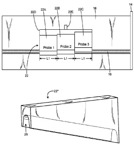
example is illustrated in FIG. 2, in which the probe 22 includes three probe
sections
22A, 22B and 22C, with each probe section having a length equal to one quarter
wavelength at the center frequency of the band. The probe sections are mounted
together in a fixed relationship, and fitted to a probe drive (not shown in
FIG. 2) for
movement in a ganged relationship toward or away from the center conductor.
The
probe sections may be attached to a probe bracket 220, for example, which is
connected to the probe drive by a post structure 22E. The probe sections could
also
be fabricated as an integral one-piece structure, instead of several
separately
constructed sections assembled together.
[0011] An exemplary design technique for designing a multi-section probe is as
follows:
[0012] 1. Determine the desired specifications as to what maximum reflection,
e.g.,
0.9 reflection magnitude, is needed in which characteristic impedance
environment,
e.g., 50 ohm, and the desired bandwidth, e.g. between 0.65 and 9 GHz, along
with
the desired reflection magnitude rm at the band edges, e.g., 0.82 reflection
magnitude. This will also fix the center frequency of the design and the
length of
each probe section as quarter wave length at the center frequency, e.g. 4.825
GHz
in the above example.
[0013] 2. For each type of design, Chebyshev or binomial (maximally flat),
determine
the design constants and number of sections needed:
[0014] Estimate initially the number of sections N. Then estimate the
constant
A = 2-(N+1)in,RzLN
) where RL is the low impedance target and ZO is the characteristic
impedance of the system, usually 50 ohm. Then, using the reflection I'm needed
at
CA 03088733 2020-07-16
WO 2019/143570 PCT/US2019/013524
the band edge, calculate the bandwidth using A f = 210 ¨ arccos (riArni)N
where
fo is the center (design) frequency of the probe. If the bandwidth is
acceptable,
continue, if it is too narrow or too wide, re-estimate the number of sections
and repeat
iteratively until a satisfactory bandwidth is obtained and the number of
sections N is
then determined.
[0015] 3. Once the number of sections N is determined, then determine the
required
characteristic impedance value for each section, using the following:
[0016] Estimate the marginal reflection coefficients Fr., = A avNiloini
and then
determine the characteristic impedance of each section iteratively by Zn+1 =
Zne2rit
starting with the 50 ohm/ZO load.
[0017] 4. Estimate the height of each section above the center conductor to
simulate
the calculated characteristic impedance for that section. The height of each
section
in this context is the distance or gap between the center conductor and the
top of the
trough of the section. This step can typically be performed through the use of
a full
30 electromagnetic field (EM) simulator such as HFSS (by ANSYS) or CST
(marketed by Computer Simulation Technology), or any other full 3D
electromagnetic
simulator.
[0018] 5. Once the height of each section is determined this way, in the final
step,
simulate the performance of the design of the whole probe using the 3D EM
simulator
to verify the broad band response and make the final tuning adjustments to the
heights if further adjustments in heights are needed.
[0019] Another embodiment of a multi-section probe uses the same height for
all
sections but varies the cross-sectional profile (also known as the trough) to
make the
trough wider and wider for successive probe sections. The troughs are
configured
to allow the probe sections when brought closer to the center conductor to
straddle
CA 03088733 2020-07-16
WO 2019/143570 PCT/US2019/013524
6
the center conductor. In this case, the probe could be made as a single
integrated
probe, with the trough made wider and wider every one-quarter wavelength.
FIGS.
3A-30 illustrate an exemplary multi-section probe 22' using probe sections
22A',
226', 22C', which are mounted together at equal heights relative to the center
conductor 18, but with different trough configurations. As with the probe 22
of FIG.
2, the multiple probe sections are mounted adjacent one another, and mounted
for
ganged movement (or made as a one single unitary structure). FIGS. 36 and 3C
show that the trough of probe section 226' is wider than the trough of probe
section
22A', and that the trough of probe section 22C' is wider than the trough of
probe
226'. Thus the probe sections have troughs each of which is wider than the
previous
adjacent probe section, with the characteristic impedance decreasing with each
widening trough. The trough width corresponds to the impedance obtained using
full
30 EM simulation.
[0020] Note that the probe bracket and post for connecting to the probe drive
are
omitted from FIGS. 3A-3C for clarity.
[0021] A further embodiment of the probe is a combination of the first two
embodiments, i.e. a multi-section probe in which both the probe height and the
trough
profile vary, i.e. from probe section to probe section.
[0022] An even better but more difficult to realize probe design is to use a
tapered
quarter wave transformer instead of multi-section transformers. This tapered
transformer has a continuous change of the impedance of the transformer
instead of
stepped change by multi-section transformer. Various methods such as
exponential
taper, triangular taper, Klopfenstein taper are used for different taper
shapes and
different applications. It is known that the Klopfenstein taper is the optimal
taper
shape for these types of quarter wave transformers. See, for example, Pozar at
chapter 5.8, pages 288-295.
[0023] FIG. 4 illustrates an exemplary embodiment of a tapered probe 22" with
a
CA 03088733 2020-07-16
WO 2019/143570 PCT/US2019/013524
7
trough 25. The height of the probe is tapered, increasing from a first end
(left in FIG.
4) to the opposite end (right in FIG. 4). The probe 22" will be mounted to the
probe
drive by a post (not shown in FIG. 4) such that the top surface is parallel to
the center
conductor.
[0024] Both techniques described above, i.e., the stepped height or varying
trough
shape, could be also used for the tapered probe, whether it is a triangular or
exponential or Klopfenstein taper.
[0025] An exemplary sequence of steps to design a tapered probe is as follows:
[0026] 1. Establish the required specifications for center frequency,
bandwidth,
desired reflection at center frequency and desired reflection at band edges
[0027] 2. Estimate the needed length L of the tapered probe (the longer, the
wider
the band width). One can estimate this length from the multi section probe
design
(e.g., Chebyshev), so that the length of the tapered probe is equal to the sum
of the
lengths of the sections of the multi-section probe structure.
[0028] 3. Determine the constants and the impedance profile for the probe from
0
up to the length L. This profile depends on the chosen taper style,
exponential,
triangular or Klopfenstein.
[0029] 4. Once the impedance profile is determined, now one needs to estimate
the
probe profile. This is done by estimating the how much the probe height above
center
conductor corresponds to that impedance. This may be done using a 3D EM
simulator such as HESS or CST. The probe height for the entire probe is
estimated,
i.e. how the taper profile or taper height varies along the probe.
[0030] 5. Simulate the probe performance using a 3D EM simulator. If
necessary,
the parameters might need to be adjusted or tuned such as probe length and
probe
height profile.
CA 03088733 2020-07-16
WO 2019/143570 PCT/US2019/013524
8
[0031] In a further embodiment, the tapered probe may incorporate both height
tapering and trough profile tapering, i.e. both the height and the trough
profile vary
continuously along the probe length.
[0032] All these embodiments can be implemented with probes that touch the
slab
lines or that do not touch the slab lines.
[0033] Although the foregoing has been a description and illustration of
specific
embodiments of the subject matter, various modifications and changes thereto
can
be made by persons skilled in the art without departing from the scope and
spirit of
the invention.