Note: Descriptions are shown in the official language in which they were submitted.
CA 03088739 2020-07-16
WO 2019/143929
PCT/US2019/014183
FAST RESPONSE TEMPERATURE SENSORS
CROSS-REFERENCE TO RELATED APPLICATIONS
[0001] This application claims the benefit of and priority to U.S.
Provisional Patent
Application No. 62/619,009 filed January 18, 2018, which is incorporated by
reference herein in its entirety.
BACKGROUND OF INVENTION
[0002] Fluid monitoring and analysis plays a key role in a variety of
industries
including aquaculture, oil and gas, mining, environmental analysis or any
industry in
which fluid parameters play a role in design or operations. Temperature is
often an
important parameter for a variety of applications and analyses.
[0003] Accurate temperature measurement of a fluid body is often
complicated by
the thermal effect of the sensor itself when immersed in the fluid. For
example, an
instrument taken from a hot environment (e.g., inside a vehicle on a warm day
into
relatively cold water), will initially yield highly inaccurate temperature
measurement.
To compensate for the thermal differences between the sensor and fluid, and
any
effect caused by the instrument itself, the temperature must be given time to
stabilize, which is referred to as temperature response time. Commonly,
temperature
response time can be as high or higher than 20 minutes, depending on
temperatures, the sensor size, and desired accuracy of the temperature
reading. A
high response time results in inefficiencies, including arising from increased
operator
time as they await temperature stabilization.
[0004] Currently, some conventional sonde designs reduce temperature
response
time to some extent. For example, sondes may use a long skinny temperature
sensor that extends into the water so the heat transfer of the surrounding
water is
much larger than the heat transfer from the instrument's thermal mass. This
can
give good results and take temperature stabilization down to a couple of
minutes, but
such conventional sonde temperature sensors take up a lot of space and tend to
be
more prone to bending and breaking. Elongated temperature sensors also are
hard
to use with modern wiper cleaning systems.
[0005] Other known sondes may employ predictive temperature measurement.
In such known systems and methods, predictive temperature measurement involves
1
CA 03088739 2020-07-16
WO 2019/143929
PCT/US2019/014183
taking multiple temperature readings over time and using a predictive
algorithm to
determine a steady state temperature. That method uses sequential readings
taken
over time and it looks at the difference from one reading to another reading
to predict
what the reading will be when the temperature stabilizes. These sondes have a
temperature sensor that is embedded in the end of the sonde and has no metal-
to-
fluid contact with the surrounding water.
[0006] It can be seen from the foregoing that there remains a need in
the art for
temperature sensors with improved response time to allow for accurate readings
to
be taken more frequently and efficiently.
SUMMARY OF THE INVENTION
[0007] Provided herein are temperature probes having reduced temperature
response time so that an accurate and reliable temperature is rapidly
obtained. This
is achieved by special positioning of a temperature sensor that measures
liquid
temperature and a thermal barrier that thermally isolates the temperature
sensor
from the rest of the temperature probe. Further improvements are achieved with
a
multiple-temperature sensor configuration to quickly and accurately calculate
ambient fluid temperature with a reduced response time. Systems and methods
may
utilize a first fluid temperature sensor to measure fluid (e.g., liquid water)
temperature and a second device temperature sensor to account for the thermal
impact of the device or probe on the ambient fluid temperature and the effect
of heat
within the device or probe on the fluid sensor measurement. This configuration
may
be generally referred to as a differential temperature sensor.
[0008] The thermally isolated liquid temperature sensor ("first
temperature
sensor") from the rest of the probe or device provides a number of advantages.
The
temperature sensor may be associated with a relatively small thermal mass, so
that
the thermal history of the temperature is minimized. The temperature sensor
may be
geometrically configured to maximize surface area exposure to surrounding
fluid,
thereby further increasing response time. The thermal isolation also minimizes
the
thermal impact of other parts of the probe, including power sources,
electronics on
the temperature measurement, and a second temperature sensor that measures
temperature of the device is thermally isolated from the first temperature
sensor. The
2
CA 03088739 2020-07-16
WO 2019/143929
PCT/US2019/014183
second temperature sensor provides further improvements in temperature
response
times.
[0009] The described probes and sensors are versatile and may be used
with a
variety of fluids, including water, in a range of applications, such as
surface, deep
water, aquifer, well or other applications. The systems and methods may be
useful in
both still and flowing fluid bodies, including immersion from a fixed location
into still
or flowing water, or trolling from a moving vehicle, such as a boat, into
water.
[0010] Any of the probes provided herein may be stand-alone devices or
may, in
turn, be incorporated within another device. For example, the probe may part
of a
sensor, such as a sonde sensor or a multiparameter sonde having a plurality of
sensors, with at least one sensor a temperature sensor that corresponds to any
of
the probes provided herein. Specific examples of sonde sensors and
multiparameter
sondes are provided in any one or more of: U.S. 9,689,855; 2016/0146777;
9,835,554; 9,778,180; 2017/0176183; and D755655, which are specifically
incorporated by reference herein for the sonde sensors, sonde bases,
multiparameter sondes, and associated components.
[0011] Provided herein is a temperature probe having a fast response time
for
measuring water temperature, comprising: i) an instrument housing forming an
interior volume and having a distal end; ii) a first temperature sensor
positioned at or
extending from the distal end of the instrument housing; iii) a second
temperature
sensor positioned in the interior volume of said instrument housing; and iv) a
thermal
barrier thermally positioned between said first temperature sensor and said
instrument housing to thermally isolate the first temperature sensor from the
instrument thermal mass.
[0012] The insulation layer may comprise an ultralight superinsulating
material
formed of one or more of ceramics, polymers, carbon, metals, carbides, such as
an
aerogel, including AIRLOY aerogel (Aerogel Technologies www.airloy.com).
[0013] Also provided herein are methods for determining the temperature
of a
fluid using any of the devices or probes described herein. For example, the
method
may comprise the steps of: a) immersing a temperature probe in a fluid,
wherein said
probe comprises: i) a first fluid temperature sensor positioned at a distal
end of the
3
CA 03088739 2020-07-16
WO 2019/143929
PCT/US2019/014183
temperature probe; and ii) a second instrument temperature sensor positioned
within
an internal volume of the probe; b) determining a ratio (Ri/R2) of thermal
resistivity
between the first temperature sensor and a surrounding fluid (Ri) and the
second
temperature sensor and the first temperature sensor (R2), c) measuring a first
.. temperature with the first temperature sensor; d) measuring a temperature
probe
temperature with the second temperature sensor; and e) determining the fluid
temperature based on the measured first temperature, the measured instrument
temperature, and the ratio R1/R2. The R1/R2 ratio may be empirically
determined,
including by the manufacturer for various conditions, by the user, or by the
instrument immediately before or during use.
[0014] Also provided is a temperature probe having a fast response time
for
measuring water temperature, comprising: i) an instrument housing forming an
interior volume and having a distal end; ii) a first temperature sensor
positioned at or
extending from the distal end of the instrument housing; and iii) a thermal
barrier
thermally positioned between said first temperature sensor and said instrument
housing to thermally isolate the first temperature sensor from the instrument
thermal
mass.
[0015] Exemplary claims are provided herein, and include, but are not
limited to,
the following specific non-limiting embodiments:
[0016] 1. A temperature probe having a fast response time for measuring a
fluid
temperature, comprising: an instrument housing forming an interior volume and
having a distal end; a first temperature sensor positioned at or extending
from the
distal end of the instrument housing; a second temperature sensor positioned
in the
interior volume of said instrument housing; and a thermal barrier thermally
positioned
.. between said first temperature sensor and said instrument housing to
thermally
isolate the first temperature sensor from the instrument thermal mass.
[0017] 2. The temperature probe of embodiment 1, further comprising: a
sensor
platform having a distal end and a proximal end, wherein said first
temperature
sensor is positioned at said sensor platform distal end and said sensor
platform
proximal end is connected to or passes through said instrument housing distal
end.
4
CA 03088739 2020-07-16
WO 2019/143929
PCT/US2019/014183
[0018] 3. The temperature probe of embodiment 2, wherein said instrument
housing comprises a sonde base and said sensor platform comprises a sonde
sensor configured to operably connect to said sonde base.
[0019] 4. The temperature probe of embodiment 2 or 3, wherein said
second
temperature sensor is positioned within said sensor platform or within said
sonde
base.
[0020] 5. The temperature probe of any of embodiments 1-4, wherein said
thermal barrier comprises an insulation layer positioned between said first
temperature sensor and said second temperature sensor, thereby thermally
isolating
said second temperature sensor from said first temperature sensor.
[0021] 6. The temperature probe of any of embodiments 1-5, wherein said
first
temperature sensor is part of a sensor platform having a distal end for
sensing a fluid
temperature and a proximal end connected to the instrument housing, wherein
said
insulation layer at least partially surrounds said proximal end of said sensor
platform.
[0022] 7. The temperature probe of any of embodiments 1-6, wherein said
insulation layer comprises a rigid aerogel.
[0023] 8. The temperature probe of any of embodiments 1-7, wherein said
insulation layer comprises an ultralight superinsulating material formed of
one or
more of a ceramic, a polymer, a carbon-containing material, a metal, a carbide
or
any combination thereof.
[0024] 9. The temperature probe of any of embodiments 1-8, wherein said
thermal barrier has a thermal conductivity of between 18-35 mW/m-K.
[0025] 10. The temperature probe of any of embodiments 1-9, further
comprising
an electronic assembly and a potting material positioned in said interior
volume,
wherein said second temperature sensor is positioned in said potting material.
[0026] 11. The temperature probe of embodiment 10, wherein said potting
material comprises a solid and/or gelatinous compound such as a thermoset
plastic
and/or silicone rubber gel.
5
CA 03088739 2020-07-16
WO 2019/143929
PCT/US2019/014183
[0027] 12. The temperature probe of any of embodiments 1-11, wherein
said
second temperature sensor is positioned along a centerline axis of said
interior
volume of said instrument housing.
[0028] 13. The temperature probe of any of embodiments 3-4, wherein said
first
temperature sensor is separated from said sonde base by a separation distance
that
is greater than or equal to 1 cm and less than or equal to 50 cm.
[0029] 14. The temperature probe of any of embodiments 1-14, wherein the
fast
temperature response time is characterized as coming to 90% or better of a
final
temperature value when submerged in a fluid for less than 2 minutes and the
temperature probe has a temperature accuracy of 0.2 C or better.
[0030] 15. The temperature probe of any of embodiments 1-14, further
characterized in having a temperature response time of 90% or better of a
final value
when submerged in a fluid for less than 20 seconds and the temperature probe
has
a temperature accuracy of 0.2 C or better.
[0031] 16. The temperature probe of any of embodiments 1-15, further
comprising a processor operably connected to said first temperature sensor and
to
said second temperature sensor, wherein during use in a liquid environment,
said
processor receives a first temperature output from said first temperature
sensor and
a second temperature output from said second temperature sensor and determines
a liquid temperature of the surrounding liquid environment.
[0032] 17. The temperature probe of embodiment 16, wherein said
processor
determines fluid temperature based on the formula:
R1
TFluid = ¨ * (T1 ¨ T2) -I- T1
R2
wherein:
TFluid is fluid temperature,
T1 is said first temperature output from said first temperature sensor,
T2 is said second temperature output from said second temperature sensor,
6
CA 03088739 2020-07-16
WO 2019/143929
PCT/US2019/014183
R1 is a thermal resistivity between said first temperature sensor and said
fluid;
and
R2 is a thermal resistivity between said first temperature sensor and said
second temperature sensor.
[0033] 18. The temperature probe of embodiment 17, wherein R1/R2 is
empirically
determined prior to use.
[0034] 19. The temperature probe of any of embodiments 17-18, wherein
R1/R2
has a value that is greater than or equal to 0.05 and less than or equal to
0.5.
[0035] 20. The temperature probe of any of embodiments 1-19, wherein the
first
temperature sensor is separated from the instrument housing by a separation
distance formed of a high surface area and thin-walled thermal conductor.
[0036] 21. The temperature probe of embodiment 20, wherein said thin-
walled
thermal conductor has a thickness that is greater than or equal to 0.1 mm and
less
than or equal to 1 cm.
[0037] 22. The temperature probe of any of embodiments 20-21, wherein said
thin-walled thermal conductor comprises titanium.
[0038] 23. The temperature probe of embodiment 3 that is part of a
multiparameter sonde comprising a plurality of independent sonde sensors, each
operably connected to said sonde base.
[0039] 24. A method for determining the temperature of a fluid comprising
the
steps of: immersing a temperature probe in a fluid, wherein said probe
comprises: a
first temperature sensor positioned at a distal end of the temperature probe;
a
second temperature sensor is positioned within an internal volume of the
probe;
determining a ratio (R1/R2) of thermal resistivity between the first
temperature sensor
and a surrounding fluid (Ri) and the second temperature sensor and the first
temperature sensor (R2), measuring a first temperature with the first
temperature
sensor; measuring a probe temperature with the second temperature sensor; and
determining the fluid temperature based on the measured first temperature, the
measured probe temperature, and the ratio R1/R2.
7
CA 03088739 2020-07-16
WO 2019/143929
PCT/US2019/014183
[0040] 25. The method of embodiment 24, wherein said step of determining
said
fluid temperature is performed using the formula:
R1
TFluid = ¨ * (T1 ¨ T2)
R2
wherein Tnuid is the fluid temperature, T1 is the first temperature, and T2 is
the probe
temperature.
[0041] 26. The method of any of embodiments 24-25, further comprising the
step
of thermally isolating the first temperature sensor from the second
temperature
sensor.
[0042] 27. The method of any of embodiments 24-26, said temperature probe
.. characterized in having a temperature response time to 90% of final value
that for an
immersion time that is less than or equal to 20 seconds and a temperature
accuracy
that is within 0.2 C.
[0043] 28. A temperature probe having a fast response time for measuring
fluid
temperature, comprising: an instrument housing forming an interior volume and
having a distal end; a first temperature sensor positioned at or extending
from the
distal end of the instrument housing; and a thermal barrier thermally at least
partially
positioned between said first temperature sensor and said instrument housing
to
thermally isolate the first temperature sensor from the instrument housing.
[0044] 29. The temperature probe of embodiment 28, further comprising a
sensor
platform having a distal end and a proximal end, wherein said first
temperature
sensor is positioned at said sensor platform distal end and said sensor
platform
proximal end is connected to said instrument housing distal end.
[0045] 30. The temperature probe of any of embodiments 28-29, wherein the
thermal barrier at least partially surrounds said proximal end of said sensor
platform.
[0046] 31. The temperature probe of any of embodiments 28-30, wherein said
thermal barrier comprises a rigid aerogel.
8
CA 03088739 2020-07-16
WO 2019/143929
PCT/US2019/014183
[0047] 32. The temperature probe of any of embodiments 28-31, wherein
the
thermal barrier comprises an ultralight superinsulating material formed of one
or
more of a ceramic, a polymer, a carbon-containing material, a thermally
insulative
metal, a carbide or a combination thereof and having a thermal conductivity of
between 18-35 mW/m-K.
[0048] Without wishing to be bound by any particular theory, there may
be
discussion herein of beliefs or understandings of underlying principles
relating to the
devices and methods disclosed herein. It is recognized that regardless of the
ultimate correctness of any mechanistic explanation or hypothesis, an
embodiment
of the invention can nonetheless be operative and useful.
BRIEF DESCRIPTION OF THE DRAWINGS
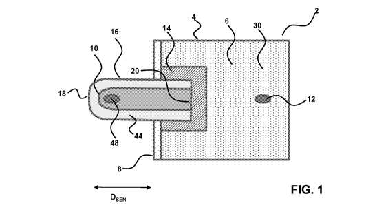
[0049] FIG. 1 is a cross-sectional view of a temperature probe having
two
temperature sensors, with a first temperature sensor (e.g., a sensor
thermistor) for
measuring a temperature in a liquid surrounding the probe and a second
.. temperature sensor (e.g., an instrument thermistor) for measuring the
temperature of
the probe instrument. The temperature sensors are thermally isolated from each
other.
[0050] FIG. 2 is a schematic cross-sectional view of a dual temperature
probe.
[0051] FIG. 3 is a schematic diagram illustrating a thermal circuit
model of the
dual temperature probe shown in FIGs. 1-2.
[0052] FIG. 4 is a reduced thermal circuit model from FIG. 3.
[0053] FIG. 5 is a corresponding mathematical model from the circuit of
FIG 4.
[0054] FIG. 6A is a perspective view of a multiparameter sonde having a
plurality
of sensors including any of the fast-response temperature probes described
herein.
.. FIG. 6B is a close up view of the distal end of a temperature sensor
("first"
temperature sensor) of the fast-response temperature probe of FIG. 6A. Adapted
from U.S. Pat. No. 9,835,554.
9
CA 03088739 2020-07-16
WO 2019/143929
PCT/US2019/014183
[0055] FIG. 7 is a flow chart of a method for determining the
temperature of a fluid
in accordance with an embodiment of the disclosure.
DETAILED DESCRIPTION OF THE INVENTION
[0056] In general, the terms and phrases used herein have their art-
recognized
meaning, which can be found by reference to standard texts, journal references
and
contexts known to those skilled in the art. The following definitions are
provided to
clarify their specific use in the context of the invention.
[0057] "Distal" and "proximal" refers to directions that are toward or
away from an
instrument body. For example, the temperature sensor for measuring liquid
temperature, such as water temperature, is said to distally located, on or
toward a
distal sensing end. The temperature sensor used to measure the probe
temperature
is said to be located proximally to the fluid-measuring temperature sensor.
[0058] "Thermal barrier" refers to a material that is a thermal
insulator and
positioned so as to reduce heat flow from one region to a second region.
"Thermally
isolate" refers to the position of a thermal barrier between components, so
that heat
transfer between components is retarded. For example, the thermal barrier may
reduce thermal conductivity by about 50%, 75%, 90%, 95%, 99% or greater. The
invention is compatible with any number of thermal barrier materials,
including those
having a thermal conductivity between about 18 and 35 mW/M-K, such as an
aerogel, a ceramic, a polymer, a carbon-containing material, carbides, and any
combination thereof.
[0059] "Sonde" refers to an instrument that measures one or more water
properties. The sonde may be a multiparameter sonde with a plurality of
independent sonde sensors, including with any of the devices and methods
described herein, including for use with any of the sondes and components
described in U.S. Pat. Nos. 9,689,855, 9,835,554, 9,778,180 and D755,655, each
of
which are specifically incorporated by reference herein in their entireties to
the extent
not inconsistent herewith. The plurality of independent sonde sensors of such
multiparameter sondes may include at least one sonde sensor having a
temperature
sensor that incorporates any of the systems described herein to achieve fast
response time for liquid temperature measurement. Generally, the first
temperature
CA 03088739 2020-07-16
WO 2019/143929
PCT/US2019/014183
sensor for measuring liquid temperature is at the distal sensing end of the
sonde
sensor. The second temperature sensor, used to measure temperature of the
instrument, may be positioned within the same sonde sensor having the first
temperature sensor, or may be positioned even further away, such as in another
portion of the sonde, such as a base unit to which the sonde sensor(s)
operably
connect.
[0060] "Fast response time" refers to a temperature probe of the instant
invention
that has an at least 50%, at least 70%, at least 90%, and up to at least 98%
improvement in temperature measurement response time compared to a
.. conventional temperature sensor without the instant dual-temperature sensor
design
and configuration, such as an equivalent sensor with only a single temperature
sensor that is not thermally isolated and/or does not have a second
temperature
sensor for measuring probe-body temperature.
[0061] "Temperature sensor" refers to a component that measures
temperature.
.. The systems and methods provided herein are compatible with any of a wide
range
of sensor types, such as thermistors, thermocouples, resistance thermometer
such
as a platinum resistance thermometer, silicon bandgap temperature sensor and
the
like.
[0062] A temperature probe (2) having a faster response time as compared
to
conventional temperature probes for measuring fluid temperature, along with
associated methods for measuring fluid temperature, are shown and described
with
reference to FIGs. 1-3, 6A and 6B. Temperature probe (2) includes an
instrument
housing (4) forming an interior volume (6). Instrument housing (4) has a
distal end
(8). Temperature probe (2) includes a first temperature sensor (10), with
active
sensing element illustrated as thermistor (48), positioned at and/or extending
from
the distal end (8) of the instrument housing (4). Temperature probe (2)
includes a
second temperature sensor (12) positioned in the interior volume (6) of the
instrument housing (4). A thermal barrier (14) is thermally positioned between
the
first temperature sensor (10) and the second temperature sensor (12) in the
instrument housing (4). Thermal barrier (14) thermally isolates the first
temperature
sensor (10) from the rest of the "thermally heavy" instrument thermal mass
(e.g., the
thermal mass of the temperature probe (2), including as generated in and/or
CA 03088739 2020-07-16
WO 2019/143929
PCT/US2019/014183
conducted along, the interior volume (6)). As an example, the thermal barrier
(14)
may have a thermal conductivity of between 18-35 mW/m-K. Optionally, the
instrument housing may comprise a distal surface that covers the thermal
barrier and
ensures a water-tight seal around the instrument housing and the temperature
sensing-portion of the probe. The distal surface may itself be a thermal
insulated,
minimizing conduction of heat from housing (4) and interior volume (6) to the
temperature sensor (10). As desired, the surface that covers the temperature
sensor
(10) may be formed of a thermal conductor, for those surfaces exposed to
liquid, and
a thermal insulator, for those surfaces in contact with the instrument housing
(4)
and/or the thermal barrier (14).
[0063] Temperature probe (2) may include a sensor platform (16) extending
a
longitudinal distance Dsen having a distal end (18) and a proximal end (20).
The first
temperature sensor (10), specifically active senor component (48), may be
positioned toward the sensor platform (16) distal end (18), and the proximal
end (20)
of the sensor platform (16) is connected to, including, as illustrated,
passing through
the distal end (8) of the instrument housing (4). Referring to FIG. 6A and 6B,
the
platform itself may be part of a sensor housing, such as sonde sensor (24)
housing
having a platform corresponding to distal end (18) to support the temperature
sensor
(10) positioned away from the probe and sensor body and toward the fluid. The
probe (2) provided herein may be incorporated entirely in a sonde sensor (24),
or a
portion in the sonde sensor (24) (e.g., first temperatures sensor) and another
portion
in the sonde base (22) (e.g., second temperature sensor, and associated
electronics).
[0064] Second temperature sensor (12) may be positioned in various
locations,
depending on the application of interest. For example, referring to FIGs. 6A
and 6B,
second temperature sensor may be positioned in a sonde base (22), and the
sensor
platform (16) includes a sonde sensor (24) configured to operably connect to
the
sonde base (22). The second temperature sensor (12) may also be positioned
within the sonde sensor housing. In other words, the probe illustrated in FIG.
1 may
be incorporated entirely within sonde sensor (24), or, alternatively, the
second
sensor may be further removed from the first sensor and positioned in a sonde
base
(22). This illustrates that the term "instrument housing" (4) is intended to
be used
12
CA 03088739 2020-07-16
WO 2019/143929
PCT/US2019/014183
broadly, and may refer to housing of sonde sensor (24) and/or sonde base (22).
The
common aspect is that a thermal barrier is positioned to thermally isolate
first
temperature sensor (10) from the rest of the probe, device or system,
including from
second temperature sensor (12) that measures the temperature of rest of the
probe/device that is thermally isolated from the first temperature sensor. The
different relative locations of the temperature sensors T1 and T2 are
reflected by
corresponding different values of R1/R2.
[0065] The thermal barrier (14) of temperature probe (2) may include an
insulation layer (26) positioned between the first temperature sensor (10) and
the
second temperature sensor (12). Positioning the thermal barrier (14) between
the
first (10) and second (12) temperature sensors thermally isolates the two
temperature sensors (10, 12) from one another, including first temperature
sensor
(1) that measures liquid temperature and second temperature sensor (12) that
measures the rest of the probe temperature (e.g., the temperature in the
interior
volume (6) of instrument housing (4)). The insulation layer (26) may surround
the
proximal end (20) of the temperature sensor (10) and/or sensor platform (16).
[0066] As one example, the insulation layer (26) may include a rigid
aerogel. As
another example, the insulation layer (26) may include an ultralight
superinsulating
material. The ultralight superinsulating material may be formed of one or more
of
ceramics, polymers, carbon, metals, carbides or any combination thereof.
[0067] The temperature probe (2) may include an electronic assembly (28)
and a
potting material (30) (schematically illustrated by the dotted pattern in FIG.
1)
positioned in said interior volume (6). The second temperature sensor (12) may
be
positioned in the potting material (30), either as an integral part of or as a
separate
component from, the electronic assembly (28). The second temperature sensor
(12)
may be positioned along a centerline axis (32) of the interior volume (6) of
the
instrument housing (4). As an example, the potting material (30) may include a
solid
compound, a gelatinous compound, or both of those types of materials. Such
potting
materials (30) may include one or both of a thermoset plastic and a silicon
rubber
gel.
13
CA 03088739 2020-07-16
WO 2019/143929
PCT/US2019/014183
[0068] The first temperature sensor (10) may be separated longitudinally
(e.g.,
along centerline axis (32)) from the second temperature sensor (12) by a
separation
distance (34). As an example, the separation distance (34) may be greater than
or
equal to 1 cm and less than or equal to 50 cm. The first temperature sensor
(10)
may be separated laterally or radially (e.g., perpendicular to centerline axis
(32))
from an opening (54) in the instrument housing (4) and/or sensor platform (16)
by a
separation distance (42). As an example, the separation distance (42) may be
between 0.1 mm and 1 cm. The separation distance (42) may be provided by the
material of construction of a thin-walled thermal conductor (44) which covers
at least
.. a portion of the length (56) and a probe end region (58) of the first
temperature probe
(10). The thin-walled thermal conductor (44) may have a thickness that is
equal to or
about equal to separation distance (42). For instance, the thickness of thin-
walled
thermal conductor (44) may be between 0.1 mm and 1 cm. The thin-walled thermal
conductor (44) may have a thickness that varies across length (56) and/or
probe end
.. region (58) of first temperature probe (10). The thin-walled thermal
conductor (44)
may be formed from a thermally-conductive material, including titanium and,
optionally, may have a proximal end that is formed of a thermally insulative
material,
such as a plastic, including those portions that are in the instrument housing
and not
exposed to liquid during use.
[0069] Covering the length (56) and probe end region (58) of first
temperature
probe (10) in the manner illustrated in FIG. 2 effectively increases a surface
area of
first temperature probe (10). In addition to the high surface area provided by
the
thin-walled thermal conductor (44), covering first temperature probe (10) in
this
fashion provides protection and structural stability to first temperature
probe (10) and
to those other components of temperature probe (2) to which first temperature
probe
(10) is attached and/or connected.
[0070] The temperature probe (2) may include a processor (36) operably
connected to the first (10) and second (12) temperature sensors. During use
(e.g.,
as submerged in a fluid such as water) of first temperature sensor in a liquid
environment, the processor (36) receives a first temperature output (38) from
the first
temperature sensor (10). In addition, during use of temperature probe (2),
processor
(36) receives a second temperature output (40) from the second temperature
sensor
14
CA 03088739 2020-07-16
WO 2019/143929
PCT/US2019/014183
(12). First (38) and second (40) temperature outputs may include an analog
signal
(e.g., a voltage or a current) that is linearly or non-linearly related to a
sensed
temperature from first (10) and second (12) temperature sensors, and processor
(36)
may include analog-to-digital (ADC) conversion functionality. As an example,
temperature probe (2) may include a data storage device, such as memory (60),
and/or transmitter, for storing and/or transmitting measured temperatures as
digital
numerical values corresponding to the sensed voltage and/or current of first
(38) and
second (40) temperature outputs.
[0071] Processor (36) can determine a liquid temperature of the
surrounding
liquid environment adjacent to the first temperature sensor (10), including
water. As
an example, processor (36) includes a central processing unit (CPU) (62)
having an
arithmetic logic unit (ALU) to perform numerical computations, including using
the
aforementioned digital numerical input values stored in memory (60) and/or
transmitted by transmitter, including a wireless transmitter module that may
be part
of the CPU, such as a Bluetooth module. The results of such numerical
computations may themselves be stored in memory (60), to be made available,
along with the raw input values and/or sensed analog voltages and/or currents,
for
further manipulations, display, cataloguing, analysis, reporting,
transmission,
storage, and any other useful end of interest to users of the disclosed
temperature
probe (2). In such embodiments, memory (60) may include a non-transient
processor (36)-readable medium (64) storing processor-executable instructions
therein for performing and/or otherwise facilitate implementing the disclosed
methods (e.g., method (100) shown in FIG. 7) for determining the temperature
of a
fluid using a temperature probe (2).
[0072] In an example, processor (36) may be positioned on or in the
electronic
assembly (28), including for example, as part of a printed circuit board
(PCB).
Alternatively, processor (36) may be replaced or augmented with other digital
and/or
analog circuitry, including, for example, an application specific integrated
circuit
(ASIC), as well as such other electronic components known to persons having
ordinary skill in the art.
[0073] Alternatively, or in addition to, ADC functionality and/or
numerical
computations being performed by a processor (36), sensed analog voltages
and/or
CA 03088739 2020-07-16
WO 2019/143929
PCT/US2019/014183
currents from first (10) and/or second (12) temperature sensors may be
transmitted
elsewhere (e.g., by wired and/or wireless data communication protocol(s)) for
further
manipulation and/or storage. For example, and as shown in FIG. 6A, the
temperature probe (2) may be part of a multiparameter sonde (46) having a
plurality
.. of independent sonde sensors (24), each independently and operably
connected to a
sonde base (22). Such multiparameter sondes (46) may include the disclosed
temperature probe (2). The multiparameter sonde (46) may include processor(s)
and/or memory of its own, which carry out the functionality of the processor
(36) and
memory (60), as described above, including within base portion (22).
[0074] The processor (36) of the temperature probe (2) may determine the
fluid temperature based on the formula:
Ri
TFluid = ¨ * (T1 ¨ T2) +
R2
wherein:
TFluid is the temperature of the probed fluid (e.g., water);
T1 is the first temperature output (38) from the first temperature sensor (10)
(Tsensor Of FIG. 3);
T2 is the second temperature output (40) from the second temperature sensor
(12) (Tinstrument of FIG. 3);
R1 is a thermal resistivity between the first temperature sensor (10) and the
probed fluid (Rsensor of FIG. 3); and
R2 is a thermal resistivity between the first temperature sensor (10) and the
second temperature sensor (12) (Rinstrument of FIG. 3).
[0075] In an embodiment, the fluid temperature (Tnu,d) is determined in
a
determining (110) step of method (100), as shown and described below with
reference to FIG. 7. In an embodiment, the ratio R1/R2 is empirically
determined
prior to use (e.g., deployment for submerging in fluid) of temperature probe
(2). The
16
CA 03088739 2020-07-16
WO 2019/143929
PCT/US2019/014183
value of the ratio R1/R2 may be between 0.05 to 0.5. In an embodiment, the
value of
the ratio R1/R2 is determined in a determining (104) step of method (100), as
shown
and described below with reference to FIG. 7.
[0076] In practice of the disclosed method (100) using temperature probe
(2),
when temperature probe (2) is submerged in a fluid, a temperature response
time to
90% or better of a final temperature value is achieved in less than 2 minutes
and
with a temperature accuracy of 0.2 C. As an example, practicing the
disclosed
method (100) using temperature probe (2) enables achieving, for the fluid
submerged temperature probe (2), a temperature response time to 90% or better
of
a final temperature value in less than 20 seconds and with a temperature
accuracy
of 0.2 C. Such rapid response times with corresponding highly accurate
temperature read-outs are a significant improvement compared to conventional
temperature sensors, including temperature sensors used in sondes.
[0077] Referring now to FIG. 7, a method (100) for determining the
temperature
of a fluid includes immersing (102) the disclosed temperature probe (2) in the
fluid.
Method (100) includes determining (104) a value of the ratio (e.g., R1/R2) of
thermal
resistivity between the first temperature sensor (10) and a surrounding fluid
(Ri) and
the second temperature sensor (12) and the first temperature sensor (12) (R2).
This
value may be empirically determined either ahead of time or immediately before
or
during measurement. Method (100) includes measuring (106) a first temperature
(e.g., Ti) with the first temperature sensor (10). Method (100) includes
measuring a
probe (2) temperature (T2) with the second temperature sensor (12). Method
(100)
includes determining (110) the fluid temperature (Tnu,d) based on the measured
first
temperature (Ti), the measured probe (2) temperature (T2), and the ratio
R1/R2. The
method (100) may include thermally isolating (112) the first temperature
sensor (10)
from the second temperature sensor (12).
[0078] Example: Fast Response Differential Temperature Sensor: Described
herein is a unique fast response temperature probe (2) that uses two
temperatures
sensors (e.g., first (10) and second (12) temperature sensors) to determine
the fluid
temperature based on the difference between strategically placed temperature
sensing elements. Such a configuration provides the ability to accurately and
17
CA 03088739 2020-07-16
WO 2019/143929
PCT/US2019/014183
reliably measure fluid temperature at a comparatively much a faster time than
a
conventional temperature sensor.
[0079] A common issue for water quality sensors is slow temperature
response
time. For conventional temperature probes that are moved from one site to
another
this can be a big issue because the user must wait for the temperature sensor
to
stabilize before they can collect data. For some instruments, the temperature
readings can take up to 20 minutes to stabilize. Over the course of a day's
work this
can cause hours of delay. The devices and methods described herein reduce
temperature sensor response time by up to 98%, including from between 80% and
98%, for example, reducing response time from 20 minutes to 20 seconds or
less.
[0080] The improved design described herein greatly improves temperature
response time. The improved design may include, for example, a thermal barrier
(14) formed of an insulative material that is referred to as "airloy", which
is a more
rigid version of aerogel. This material has extremely good thermal insulation
properties that have not been previously available. This material is useful in
isolating
the thermal mass of the rest of the temperature probe (2) from the first
temperature
sensor (10). The insulative material resists the heat transfer from the
thermal mass
of the temperature probe (2) to the temperature sensing element (e.g.
thermistor) of
the first temperature sensor (10). The temperature sensing element of the
first
temperature sensor (10) is also positioned further into the fluid sample so
there is
higher surface area and thinner wall sections. This increases the thermal heat
transfer from the fluid to the temperature sensing element of the first
temperature
sensor (10). This design significantly reduces the response time, including
from 20
to 2 minutes, at least in part, due to the new insulation and by extending the
temperature sensing element of the first temperature sensor (10) further into
the fluid
sample.
[0081] While two minutes is an improvement over conventional sonde
temperature sensors, the response time can be even further reduced by
introducing
a second temperature sensor (12) that is placed inside potting material (30)
positioned in an interior volume (6) of an instrument housing (4) of the
temperature
probe (2). The second temperature sensor (12) is used to measure the
temperature
of the potting material (30) in the interior volume (6), which holds a lot of
thermal
18
CA 03088739 2020-07-16
WO 2019/143929
PCT/US2019/014183
mass. Since there are two temperature sensors¨the first (10) and the second
(12)
sensors¨how the thermal mass of the temperature probe (2) interior volume (6)
affects the measurements of the first temperature sensor (10) (that is in
close
proximity to the water sample) may be determined. This can improve response
time
from 2 minutes to a matter of seconds, for example, 20 seconds or less.
[0082] Technical Description and Experimental Results
[0083] FIG. 2 is a schematic diagram illustrating a cross-sectional view
of a dual
temperature probe (2) in accordance with an embodiment of the disclosure.
FIGs. 3-
5 are schematic diagrams illustrating a thermal circuit model of the dual
temperature
probe (2) shown in FIGs. 1-2. The heat transfer of the temperature probe (2)
shown
in FIG. 4 is modeled using Fourier's Law, as shown in FIG. 5. In the following
discussion, some electric circuit analogies are made to the thermodynamic
system of
FIG. 5 to simplify the analysis.
Table 1 ¨ Variable analogies between electrical and thermal systems
Electrical System Heat Transfer System
Voltage (V) Temperature delta (Ti-T2)
Current (I) Heat flux (heat flow rate)
Resistance (R) Thermal resistance (R)
[0084] FIG. 5 depicts an application of the electrical/thermal analogy
to the design
shown in FIG 4. Using anologies, one can model a simple resistor in series to
represent the heat transfer.
[0085] The conduction heat transfer is described by equation 1:
kA(Ti¨T2)
Q = ___________ (Equation 1)
Where: Q = heat transfer per unit time
k = thermal conductivity
A = area
= temperature value reported by first temperature sensor (10)
T2 = temperature reported by second temperature sensor (12)
d = distance (72) between first (48) and second (50) thermistors
19
CA 03088739 2020-07-16
WO 2019/143929
PCT/US2019/014183
[0086] Resistance components of the conduction heat transfer are
described in
equation 2:
1 kA 1 kA
¨ = ¨ or ¨ = ¨ (Equation 2)
R1 d R2
Where: R1 = thermal resistivity between the first temperature sensor (10) and
the
probed fluid having a temperature of TFluid
R2 = thermal resistivity between the first (10) and second (12) temperature
sensors
[0087] Combining Equation 2 into Equation 1 by substituting = Lid
results in
Equation 3:
T1¨T2
Q = - (Equation 3)
[0088] FIG. 5 is a thermal model of first (10) and second (12)
temperature
sensors in series, as described by Equation 3. Thermal heat flux is analogous
to
electrical current, so just as current is equal through series resistors, heat
flux is
equal for both thermal resistances (Ri and R2) in heat transfer, as described
in
Equation 4.
Qi = Q2 (Equation 4)
[0089] Applying Equation 4 to Equation 3 as described in FIG. 5, results
in
Equation 5:
TF1uid¨T1 =1-772
(Equation 5)
R1 R2
[0090] Solving for Mud results in Equation 6, which provides the basis
for the
calculation of water temperature in a dual temperature sensor system:
TFluid = * (T1 ¨ T2) + T1 (Equation 6)
R2
CA 03088739 2020-07-16
WO 2019/143929
PCT/US2019/014183
[0091] T1 and T2 are measured with the first (10) and the second (12)
temperature sensors, respectively (e.g., using thermistors as sensing
elements).
The term ¨ C is a constant that may be empirically determined by testing the
R2
response of the temperature probe (2) to temperature changes with a known
value of
TFluid. If a value C is used that is too large, then the response of TFluid
can overshoot.
If a value of C used is too small, then the response will be slower.
[0092] Fourier's law and application of Equation 6 includes a number of
assumptions on an idealized system. For example, Fourier's law assumes there
is
no internal heat generation in the interior housing (6) of the temperature
probe (2)
and that the materials are homogeneous and isotropic (same thermal gradient in
all
directions).
[0093] The position of the placement of the second temperature sensor
(12)
and/or its respective sensing element (e.g., a second thermistor (50)) in the
interior
volume (6) of the temperature probe (2) can be adjusted to provide separation
from
the position of the placement of the first temperature sensor (10) and/or its
respective sensing element (e.g., a first thermistor (48)) to give a faster or
slower
temperature response time. For example, increasing a distance of the first
thermistor (10) from the probed fluid results in a slower response (e.g.,
increases
temperature response time), while decreasing the distance of the first
thermistor (10)
from the probed fluid results in a faster response (e.g., decreases
temperature
response time). However, in practicing the disclosed devices, systems, and
methods, effectively modeling the thermodynamics of temperature probe (2)
relies
less on the temperature response time, and more on the placement positions of
of
the temperature sensors (10 and/or 12) and/or their respective thermistors in
or on
the temperature probe (2).
[0094] Moving the second temperature sensor (12) and/or its second
therrmistor
(50) closer to the first temperature sensor (10) and/or its first thermistor
(48) will have
the effect of increasing the value of C, while moving the second temperature
sensor
(12) and/or its second therrmistor (50) further away from the first
temperature sensor
(10) and/or its first thermistor (48) will have the effect of decreasing the
value of C.
When the C term is larger due to placement position of the second temperature
21
CA 03088739 2020-07-16
WO 2019/143929 PCT/US2019/014183
sensor (12) and/or its second therrmistor (50) the temperature measurement
accuracy of the first (10) and second (12) temperature sensors and/or their
respective thermistors will have a greater effect on the total accuracy of the
fluid
temperature measurement due to multiplying the difference in temperatures. In
practicing the disclosed devices, systems, and methods, values of C may be in
the
range between 0.05 and 1.0, where a value of 1 means that the thermal
resistances
are equal between the probed fluid and first thermistor (48) (R1), and between
the
first (48) and second (50) thermistors, respectively.
[0095] In order to address some of the variation from the theoretical
ideal
assumptions, such as the internal heat generation, the disclosed temperature
probe
(2) is designed to dissipate a minimal amount of energy during operation to
reduce
any self heating effects. In order to account for the other small variations
tending to
deviate from the ideal Fourier model, an improvement in the form of Equations
7, 8
and 9, below, introduce terms providing for filtering of a first temperature
output (38)
of the first temperature sensor (10) and/or its respective thermistor (48),
and
providing for filtering of a second temperature output (40) of the second
temperature
sensor (12) and/or its respective thermistor (50). Taken together, these
filtering-
related terms can enable users, designers and programmers of the disclosed
temperature probe (2) to optimize the temperature response time to give faster
overall response with minimal overshoot error. For example, and without
limitation:
y (n) = ¨ Eit14=1 a(i) * y(n ¨ i) + Eitv=1 b (i) * Ti(n ¨ i) (Equation 7)
z (n) = ¨ Er=lc (i) * z (n ¨ i) + Eitv=1 d(i) * T2 (n ¨ i) (Equation 8)
7' Fluid (n) = T (n) + C* (n) ¨ T 2(n)) + y (n) + z (n) (Equation 9)
Where T1, T2, and C are defined above with reference to Equations 1 and 6;
a(i) and
b(i) are filter coefficients for the first temperature output (38); c(i) and
d(i) are filter
coefficients for the second temperature output (40); and Z(b(i)) = Z(d(i)) =
0.
[0096] Filters (52) on the first (38) and second (40) temperature
outputs may
have a high pass or band pass filter type response, with each having a gain =
0 at
DC. Filters (52) may include analog filtering circuitry for implemented the
disclosed
filtering scheme. Alternatively, the disclosed filtering scheme may be
digitally
22
CA 03088739 2020-07-16
WO 2019/143929
PCT/US2019/014183
implemented by processor (36). When the measured values T1 and T2 have a rapid
rate of change in time, then the y(n) and z(n) terms will contribute to the
sum in
Equation 9. The sum of the coefficients b(i) and d(i) are set to zero
respectively to
force the y(n) and z(n) terms to zero in steady state.
[0097] Various methods using different metrics can be used for determining
optimal values and/or ranges of values for filter coefficients a(i), b(i),
c(i), and d(i).
For example, when a(i)= c(i) = 0, which defines an FIR (finite impulse
response)
filter, least-squares solutions can be used to determine the values and/or
ranges of
values for filter coefficients b(i) and d(i). Alternatively, in some
embodiments, non-
linear optimization methods can be used for optimizing the more general IIR
(infinite
impulse response) filter coefficient values. Accordingly, any of the probes or
methods
described herein may use one or more filters.
[0098] Any of the probes provided herein may be loaded/pressed into a
sonde,
including any of those described in U.S. Pat. Nos. 9,689,855, 9,835,554,
9,778,180
.. and D755,655, for example. The temperature sensor, optionally including the
entire
temperature probe, may be removably connected to the sonde, including a sonde
for
a multiparameter sonde. See, e.g., FIG. 6A-6B. Various different materials,
including
thermal barrier materials, and configurations can be utilized to thermally
isolate the
first temperature sensor that is used to measure liquid temperature. As
described,
the different configurations may be characterized in terms of the ratio R1/R2.
The
performance characteristics can be quantified in terms of time required to
come to a
certain percentage of final temperature. Table 2 below summarizes the
performance
characteristics in terms of time to 63% (t63), 90% (t90) and 95% (t95) for
various
R1/R2 with overshoot. A good metric for sensor response time is the t90 value.
Equation (6) is used to generate the data, with a gain (Ri/R2) of 0
corresponding to a
result that is from T1 only and is the slowest. For overly large R1/R2 the
signal can
overshoot, with attendant degradation in performance characteristics. There is
an
about 7.6x improvement in response speed, as shown by gain = 0.25 compared to
0
(compare t90 for gain = 0 of 5 minutes 4 seconds to t90 of 40 seconds for gain
=
0.25).
23
CA 03088739 2020-07-16
WO 2019/143929
PCT/US2019/014183
[0099] Table 2: Response time characteristics for various gain
configurations
Gain =R1/R2 t63 t90 t95 Overshoot
( C)
0 0 min 9 sec 5 min 4 sec 10 min 46 sec 0
0.125 0 min 14 sec 1 min 57 sec 4 min 20 sec 0
0.250 0 min 4 sec 0 mi 40 sec 1 min 16 sec 0.164
0.325 0 min 4 sec 0 min 13 sec 0 min 36 sec 0.492
0.375 0 min 4 sec 0 min 9 sec 0 min 18 sec 0.726
0.425 0 min 4 sec 0 min 9 sec 0 min 9 sec 0.991
0.475 0 min 4 sec 0 min 9 sec 0 min 9 sec 1.266
0.525 0 min 4 sec 0 min 9 sec 0 min 9 sec 1.540
STATEMENTS REGARDING INCORPORATION BY REFERENCE
AND VARIATIONS
[0100] All references throughout this application, for example patent
documents
including issued or granted patents or equivalents; patent application
publications;
and non-patent literature documents or other source material; are hereby
incorporated by reference herein in their entireties, as though individually
incorporated by reference, to the extent each reference is at least partially
not
inconsistent with the disclosure in this application (for example, a reference
that is
partially inconsistent is incorporated by reference except for the partially
inconsistent
portion of the reference).
[0101] The terms and expressions which have been employed herein are used
as
terms of description and not of limitation, and there is no intention in the
use of such
terms and expressions of excluding any equivalents of the features shown and
described or portions thereof, but it is recognized that various modifications
are
possible within the scope of the invention claimed. Thus, it should be
understood that
although the present invention has been specifically disclosed by preferred
embodiments, exemplary embodiments and optional features, modification and
variation of the concepts herein disclosed may be resorted to by those skilled
in the
art, and that such modifications and variations are considered to be within
the scope
of this invention as defined by the appended claims. The specific embodiments
provided herein are examples of useful embodiments of the present invention
and it
will be apparent to one skilled in the art that the present invention may be
carried out
using a large number of variations of the devices, device components, methods
steps set forth in the present description. As will be obvious to one of skill
in the art,
24
CA 03088739 2020-07-16
WO 2019/143929
PCT/US2019/014183
methods and devices useful for the present methods can include a large number
of
optional composition and processing elements and steps.
[0102] When a group of substituents is disclosed herein, it is understood
that all
individual members of that group and all subgroups are disclosed separately.
When
a Markush group or other grouping is used herein, all individual members of
the
group and all combinations and subcombinations possible of the group are
intended
to be individually included in the disclosure.
[0103] Every formulation or combination of components described or
exemplified
herein can be used to practice the invention, unless otherwise stated.
[0104] Whenever a range is given in the specification, for example, a
temperature
range, a ratio range, a time range, or a resistivity range, all intermediate
ranges and
subranges, as well as all individual values included in the ranges given are
intended
to be included in the disclosure. It will be understood that any subranges or
individual values in a range or subrange that are included in the description
herein
.. can be excluded from the claims herein.
[0105] All patents and publications mentioned in the specification are
indicative of
the levels of skill of those skilled in the art to which the invention
pertains.
References cited herein are incorporated by reference herein in their entirety
to
indicate the state of the art as of their publication or filing date and it is
intended that
this information can be employed herein, if needed, to exclude specific
embodiments
that are in the prior art.
[0106] As used herein, "comprising" is synonymous with "including,"
"containing,"
or "characterized by," and is inclusive or open-ended and does not exclude
additional, unrecited elements or method steps. As used herein, "consisting
of"
.. excludes any element, step, or ingredient not specified in the claim
element. As used
herein, "consisting essentially of" does not exclude materials or steps that
do not
materially affect the basic and novel characteristics of the claim. In each
instance
herein any of the terms "comprising", "consisting essentially of" and
"consisting of"
may be replaced with either of the other two terms. The invention
illustratively
described herein suitably may be practiced in the absence of any element or
elements, limitation or limitations which is not specifically disclosed
herein.
CA 03088739 2020-07-16
WO 2019/143929
PCT/US2019/014183
[0107] All art-known functional equivalents, of any such materials and
methods
are intended to be included in this invention. The terms and expressions which
have
been employed are used as terms of description and not of limitation, and
there is no
intention that in the use of such terms and expressions of excluding any
equivalents
of the features shown and described or portions thereof, but it is recognized
that
various modifications are possible within the scope of the invention claimed.
Thus, it
should be understood that although the present invention has been specifically
disclosed by preferred embodiments and optional features, modification and
variation of the concepts herein disclosed may be resorted to by those skilled
in the
art, and that such modifications and variations are considered to be within
the scope
of this invention as defined by the appended claims.
26