Note: Descriptions are shown in the official language in which they were submitted.
- 1 -
DEVICE FOR ENDO VASCULAR AORTIC REPAIR AND METHOD OF USING THE
SAME
TECHNICAL FIELD
[0001] The present disclosure relates to a device and method of using
same for
endovascular aortic repair, including repair of aortic valve disease, aortic
stenosis, ascending
aortic aneurysms, aortic insufficiency, aortic regurgitation, ascending
aneurysm, bicuspid valve
disease, and/or Type A dissections.
BACKGROUND
[0002] The normal aortic root and the ascending aorta are composed of the
aortic
annulus, the sinuses of Valsalva, the sinutubular junction, and the tubular
portion. The challenge
facing practitioners of endovascular repair of ascending aortic aneurysms is
that there is a very
short proximal landing zone at the level of the sinutubular junction, there is
variable coronary
anatomy from patient to patient, and, in many cases, there is involvement of
the aortic valve with
either stenosis or insufficiency. Generally speaking, and as discussed in the
article SURGERY
INSIGHT: THE DILATED ASCENDING AORTA ¨ INDICATIONS FOR SURGICAL
INTERVENTION, by James E. Davies and Thralf M. Sundt published in Nature
Clinical
Practice Cardiovascular Medicine (2007). There are three basic types of
involvement of the
ascending aorta, designated as Type A, B, or C. These will be discussed in
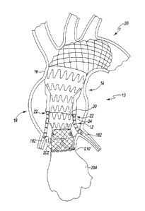
further detail below
and are shown in FIGS. 1A-1C, which have been reproduced from the referenced
article.
Date Recue/Date Received 2021-10-12
-2-
[0003] Type A aneurysms are most commonly found in younger patients and
patients
with connective tissue disorders such as Marfan syndrome. The anatomical
characteristics of
Type A aneurysms are dilatation of the sinuses of Valsalva with or without
dilatation of the
aortic annulus. The sinutubular junction is most often dilated. The valve
could be normal,
stenotic or insufficient. An example of a Type A aneurysm is shown in FIG. 1A.
[0004] The anatomical characteristics of Type B aneurysms are dilatation
of the tubular
portion. Initially the sinutubular junction may be normal or mildly dilated,
however as the
aneurysm grows, it stretches the sinutubular junction and may eventually lead
to aortic
insufficiency. The valve could be normal, stenotic or insufficient. The bulk
of the aneurysm is at
the level of the tubular aorta. An example of a Type B aneurysm is shown in
FIG. 1B.
[0005] The anatomical characteristics of Type C aneurysms are dilatation
of the sinuses
of Valsalva, sinutubular junction and the tubular portion of the aorta. The
valve could be normal,
stenotic or insufficient. Type B and C aneurysms are most commonly found in an
older group of
patients. An example of a Type C aneurysm is shown in FIG. 1C.
[0006] There are devices clinically used for endovascular repair of
ascending aortic
aneurysms. Although transcatheter valves are a clinical reality, none in
clinical use have been
designed with the purpose of endovascular repair of multiple types of
ascending aortic
aneurysms. Indeed, a device is needed that can treat different anatomical
variations of ascending
aortic aneurysms, create effective proximal and distal seal zones within the
aorta, and have a
durable valve component, but that also allows for future valve re-
interventions. A device is also
needed that would allow for treatment of different coronary anatomical
variations among the
patient population, allow future coronary re-intervention, but that also
avoids coronary
compression, and enables treatment of possible paravalvular leaks.
Date Recue/Date Received 2021-10-12
-3-
SUMMARY
[0007] According to one aspect of the disclosure, an endograft device for
endovascular
repair of ascending aortic aneurysms is disclosed. The endograft device
includes a first prosthetic
component that has a proximal frame and a distal frame that is secured to the
proximal frame and
extends to a distal end of the first prosthetic component. The endograft
device also includes at
least one conduit that is secured to the first prosthetic component and that
is positioned adjacent
to the proximal frame, and a second prosthetic component that is secured to a
proximal end of
the first prosthetic component. The second prosthetic component includes a
balloon-expandable
frame extending distally from a proximal end of the second prosthetic
component and a self-
expanding frame that is connected to the balloon-expandable frame and extends
to a distal end of
the second prosthetic component. The endograft device also includes a valve
element that is
secured to the balloon-expandable frame at the proximal end of the second
prosthetic component.
[0008] In some embodiments, the self-expanding frame may have an hourglass
shape. In
some embodiments, the self-expanding frame may include a first section that
tapers inwardly
between a proximal end and a distal end. The endograft device may also include
a second section
having a proximal end that is secured to the distal end of the first section.
The second section
may taper outwardly between the proximal end of the second section and a
distal end of the
second section. Additionally, in some embodiments, the proximal end of the
first section may be
connected to a distal end of the balloon-expandable frame.
[0009] In some embodiments, the self-expanding frame may include a third
section that
extends proximally from the proximal end of the first section. The third
section may have a
passageway defined therein, and the balloon-expandable frame may be positioned
in the
Date Recue/Date Received 2021-10-12
-4-
passageway of the third section of the self-expanding frame. In some
embodiments, the balloon-
expandable frame may be expandable between an unexpanded position in which an
outer surface
of the balloon-expandable frame is spaced apart from an inner surface of the
self-expanding
frame and an expanded position in which the outer surface of the balloon-
expandable frame is
engaged with the inner surface of the self-expanding frame.
[0010] In some embodiments, a plurality of fibers may be attached to the
third section of
the self-expanding frame. When the balloon-expandable frame is in the expanded
position, the
outer surface of the balloon-expandable frame may be engaged with the
plurality of fibers.
[0011] In some embodiments, the proximal frame of the first prosthetic
component may
have a passageway defined therein, and the distal end of the second prosthetic
component may
be positioned in the passageway of the first prosthetic component.
[0012] In some embodiments, the conduit may include a pair of conduits
positioned on
opposite sides of the first prosthetic component. Additionally, in some
embodiments, the conduit
may have a proximal opening that is positioned adjacent to a proximal end of
the first prosthetic
component.
[0013] In some embodiments, the proximal frame may include a first
section secured to
the distal end of the second prosthetic component, and a second section
connected to the first
section. The second section may taper outward between a proximal end connected
to the first
section and a distal end. The conduit may have a distal opening defined in the
second section of
the proximal frame.
[0014] Additionally, in some embodiments, the endograft device may
include a stent
having a distal end positioned in the proximal opening of the at least one
conduit and a proximal
end configured to be positioned in a coronary artery.
Date Recue/Date Received 2021-10-12
-5-
[0015] In some embodiments, an outer surface of the second prosthetic
component and
an outer surface of the proximal frame of the first prosthetic component may
be covered such
that fluid is prevented from passing therethrough. Additionally, an outer
surface of the distal
frame of the first prosthetic component may be uncovered such that is fluid
permitted to pass
therethrough.
[0016] According to another aspect, a transcatheter valve is disclosed.
The transcatheter
valve includes a frame component having a balloon-expandable frame extending
distally from a
proximal end of the frame component and a self-expanding frame secured to the
balloon-
expandable frame. The self-expanding frame includes a first section that
tapers inwardly between
a proximal end and a distal end, and a second section that tapers outwardly
between a proximal
end secured to the distal end of the first section and a distal end. A valve
element is positioned in
the balloon-expandable frame at the proximal end of the frame component.
[0017] In some embodiments, the frame component may be a dual-frame
component.
The self-expanding frame may be an outer frame of the dual-frame component and
may have a
passageway defined therein. The balloon-expandable frame may be an inner frame
of the dual-
frame component that is positioned in the passageway defined in the self-
expanding frame.
Additionally, the balloon-expandable frame may be expandable between an
unexpanded position
in which an outer surface of the balloon-expandable frame is spaced apart from
an inner surface
of the self-expanding frame and an expanded position in which the outer
surface of the balloon-
expandable frame is engaged with the inner surface of the self-expanding
frame.
[0018] In some embodiments, a plurality of fibers may be attached to the
self-expanding
frame. When the balloon-expandable frame is in the expanded position, the
outer surface of the
balloon-expandable frame may be engaged with the plurality of fibers.
Additionally, in some
Date Recue/Date Received 2021-10-12
-6-
embodiments, an outer surface of the first section of the self-expanding frame
may be uncovered
such that fluid is permitted to pass therethrough and an outer surface of the
second section of the
self-expanding frame may be covered such that fluid is prevented from passing
therethrough.
[0019] In some embodiments, the self-expanding frame may include an
elongated section
extending distally from the second section. The elongated section may have a
length that is
greater than a combined length of the first section and the second section.
Additionally, in some
embodiments, the self-expanding frame may be covered with at least one of a
collagen and
hydrogel. In some embodiments, the valve element may be one of a bicuspid
valve and a
tricuspid valve.
[0020] According to another aspect, a method of repairing a patient's
aorta is disclosed.
The method includes introducing a first prosthetic component into the
patient's aorta such that a
proximal frame of the first prosthetic component is positioned in the
ascending aorta and a distal
frame of the first prosthetic component is positioned in the aortic arch of
the patient's aorta,
advancing a covered stent through a conduit defined in the first prosthetic
component into a
coronary artery of the patient's aorta, securing a second prosthetic component
to a proximal end
of the first prosthetic component in the patient's aorta, and expanding a
proximal section of the
second prosthetic component into engagement with the aortic annulus of the
patient's aorta such
that a valve secured to the proximal section is positioned in the aortic
annulus proximal to the
coronary arteries.
[0021] In some embodiments, expanding the proximal section of the second
prosthetic
component may include operating a balloon-expandable frame. Additionally, in
some
embodiments, expanding the proximal section of the second prosthetic component
may include
permitting a self-expanding frame to expand into engagement with the aortic
annulus, and
Date Recue/Date Received 2021-10-12
-7-
operating the balloon-expandable frame may include advancing an outer surface
of the balloon-
expandable frame into engagement with an inner surface of the self-expanding
frame after the
self-expanding frame is engaged with the aortic annulus.
[0022] In some embodiments, operating the balloon-expandable frame may
include
advancing an outer surface of the balloon-expandable frame into engagement
with the aortic
annulus.
[0023] In some embodiments, an outer surface of the second prosthetic
component and
an outer surface of the proximal frame of the first prosthetic component may
be covered such
that fluid is prevented from passing therethrough. Additionally, an outer
surface of the distal
frame of the first prosthetic component may be uncovered such that is
permitted to pass
therethrough.
[0024] In some embodiments, introducing the first prosthetic component
into the
patient's aorta and advancing the covered stent through the conduit defined in
the first prosthetic
component into the coronary artery of the patient's aorta may be performed
during a first
surgical procedure. In some embodiments, securing the second prosthetic
component to the
proximal end of the first prosthetic component and expanding the proximal
section of the second
prosthetic component into engagement with the aortic annulus of the patient's
aorta may be
performed during a second surgical procedure different from the first surgical
procedure.
[0025] In some embodiments, the method may also include introducing the
second
prosthetic component into the ascending aorta prior to introducing the first
prosthetic component.
Date Recue/Date Received 2021-10-12
-8-
BRIEF DESCRIPTION OF THE DRAWINGS
[0026] Embodiments of the present disclosure will now be described by way
of example
in greater detail with reference to the attached figures, in which:
[0027] FIG. 1 is an illustrative aorta;
[0028] FIG. lA is an example of a Type A aneurysm;
[0029] FIG. 1B is an example of a Type B aneurysm;
[0030] FIG. 1C is an example of a Type C aneurysm;
[0031] FIG. 2 is partial cutaway view of an aorta with an embodiment of
an endovascular
prosthetic device implanted therein;
[0032] FIG. 3 is an elevation view of a proximal prosthetic component of
the
endovascular prosthetic device of FIG. 2;
[0033] FIG. 4 is an elevation view of a distal prosthetic component of
the endovascular
prosthetic device of FIG. 2;
[0034] FIG. 5 is a cross sectional view of the distal prosthetic
component of FIG. 4 taken
along the line 5-5 in FIG. 4;
[0035] FIG. 6 is a partial cutaway view of the aorta with the distal
prosthetic component
of FIG. 3 implanted therein;
[0036] FIG. 7 is a view similar to FIG. 6 showing stents extending from
the distal
prosthetic component;
[0037] FIG. 8 is an elevation view of another embodiment of a proximal
prosthetic
component of the endovascular prosthetic device of FIG. 2;
[0038] FIG. 9 is an elevation view of a self-expanding outer frame of the
proximal
prosthetic component of FIG. 8;
Date Recue/Date Received 2021-10-12
-9-
[0039] FIG. 10 is an elevation view of a balloon-expandable inner frame of
the proximal
prosthetic component of FIG. 8;
[0040] FIG. 11 is a perspective view a proximal end of the proximal
prosthetic
component of FIG. 8;
[0041] FIG. 12 is a cross-sectional elevation view of the proximal
prosthetic component
of FIG. 8 taken along the line 12-12 in FIG. 11;
[0042] FIG. 13 is a plan view of the proximal prosthetic component of FIG.
8 showing
the inner frame in an unexpanded position;
[0043] FIG. 14 is a plan view similar to FIG. 13 showing the inner frame
in an expanded
position;
[0044] FIG. 15 is a partial cutaway view of the aorta with the distal
prosthetic component
of FIG. 4 secured to the proximal prosthetic component of FIG. 8;
[0045] FIG. 16 is a view similar to FIG. 15 showing the inner frame in an
expanded
position;
[0046] FIG. 17 is an embodiment of a transcatheter valve device similar to
the proximal
prosthetic component of FIG. 3;
[0047] FIGS. 18-19 are partial cutaway views of the aorta with the
transcatheter valve of
FIG. 17 implanted therein;
[0048] FIG. 20 is another embodiment of a transcatheter valve device
similar to the
proximal prosthetic component of FIG. 8; and
[0049] FIGS. 21-22 are partial cutaway views of the aorta with the
transcatheter valve of
FIG. 20 implanted therein.
Date Recue/Date Received 2021-10-12
-10-
DETAILED DESCRIPTION OF THE DRAWINGS
[0050] While the concepts of the present disclosure are susceptible to
various
modifications and alternative forms, specific exemplary embodiments thereof
have been
illustrated by way of example in the drawings and will herein be described in
detail.
[0051] Terms representing anatomical references, such as anterior,
posterior, medial,
lateral, superior, inferior, distal, proximal, etcetera, may be used
throughout the specification in
reference to the orthopaedic implants and surgical instruments described
herein as well as in
reference to the patient's natural anatomy. Such terms have well-understood
meanings in both
the study of anatomy and the field of orthopaedics. Use of such anatomical
reference terms is
intended to be consistent with their well-understood meanings unless noted
otherwise. For
example, the term "proximal" refers to the direction that is generally closest
to the heart, and the
term "distal" refers to the direction that is generally furthest from the
heart.
[0052] Referring to FIGS. 2-16, exemplary designs of an endovascular
prosthetic device
or endograft device 10 (hereinafter device 10) are shown. The device 10 is
intended for the
treatment of most ascending aortic aneurysms and is configured to treat any
type of ascending
aneurysm regardless of involvement of the aortic valve and the sinuses of
Valsalva. As described
in greater detail below, the device 10 permits future coronary and aortic
valve interventions as
well as extension of a fenestrated/ branch graft into the aortic arch. Part of
the device 10 may
also be modified and used as a transcatheter valve, as described in greater
detail below in regard
to FIGS. 17-22. Such a valve may be introduced transfemorally or through the
subclavian artery
or the apex of the heart.
[0053] Referring now to FIGS. 2-7, the device 10 includes a proximal
component 12 that
is attached to a distal component 14. As shown in FIG. 2, the distal component
14 may be
Date Recue/Date Received 2021-10-12
- 11 -
secured to the proximal component 12 when implanted into a patient's aorta 16.
When
implanted, the proximal component 12 is positioned in the patient's ascending
aorta 18, while the
distal component 14 extends distally into the arch 20 of the patient's aorta
16. The distal
component 14 includes a pair of "Endo-cabrol conduits" or conduits 22, and
each conduit 22 is
sized to receive a catheter or stent 24 for coronary blood flow, as described
in greater detail
below. The device 10 is configured to treat all ascending aneurysms with or
without dilated
sinutubular junctions and aortic valve disease.
[0054] As shown in FIG. 3, the proximal component 12 includes a frame 26
that extends
from a proximal end 28 to a distal end 30. The frame 26 is attached to a valve
32 (shown in
phantom), which is positioned at the proximal end 28 of the component 12. In
the illustrative
embodiment, the valve 32 is configured as a bicuspid valve. It should be
appreciated that in other
embodiments the valve 32 may be tricuspid or quadracuspid. The valve 32 may be
constructed
from treated bovine pericardium or other suitable proven biological or
synthetic material. When
the proximal component 12 is implanted into the patient's aorta 16, the valve
32 replaces the
aortic valve and permits fluid (i.e., blood) to selectively pass from the
heart and into a
passageway 36 extending through the proximal component 12.
[0055] The valve 32 is housed in a balloon-expandable frame 34 of the
frame 26. As
shown in FIG. 3, the balloon-expandable frame 34 is embodied as a balloon-
expandable stent 38
that extends distally from the proximal end 28 of the component 12 and has a
length 40 of
approximately 15 mm. In other embodiments, the stent 38 may be longer or
shorter depending
on, for example, the patient's anatomy. The stent 38 is tubular and is
constructed of a metallic
material, such as, nitinol, stainless steel, or other implant grade metallic
material, in an open-cell
configuration. It should be appreciated that in other embodiments the stent 38
may be formed
Date Recue/Date Received 2021-10-12
- 1 2 -
from a polymeric material and may be formed in, for example, a Z-stent
configuration. In the
illustrative embodiment, the outer surface 42 of the stent 38 is covered with
low-profile
polyester, ePTFE, or other nonporous covering material 44 that prevents fluid
from passing
through the outer surface 42. However, it should be appreciated that the stent
38 may be covered
with standard polyester or other nonporous materials.
[0056] As shown in FIG. 3, the stent 38 of the balloon-expandable frame 34
has a
diameter 46. As described in greater detail below, the balloon-expandable
frame 34 is
expandable during implantation from an unexpanded diameter (not shown) to the
expanded
diameter 46. In the illustrative embodiment, the expanded diameter 46 is equal
to approximately
26 mm when the frame 34 is expanded. In other embodiments, the expanded
diameter may be
greater than or less than 26 mm depending on, for example, the patient's
anatomy. Examples of
balloon-expandable stents are described in U.S. Patent No. 5,102,417 entitled
"Expandable
Intraluminal Graft, and Method and Apparatus for Implanting an Expandable
Intraluminal Graft"
by Julio C. Palmaz and U.S. Patent No. 6,582,462 entitled "Valve Prosthesis
for Implantation in
the Body and a Catheter for Implanting Such Valve Prosthesis" by Henning Rud
Andersen et al..
In the illustrative embodiment, the diameter 46 is oversized relative to the
diameter of the aortic
annulus 210 (see FIG. 1) such that an interference fit is created between the
stent 38 and the
annulus 210 when the component 12 is implanted and the stent 38 is expanded,
as described in
greater detail below.
[0057] The balloon-expandable frame 34 is attached to a self-expanding
frame 50. In the
illustrative embodiment, the distal end 52 of the balloon-expandable frame 34
is secured to the
proximal end 54 of the frame 50 by stitching or sewing the frames 34, 50
together, thereby
forming the frame 26 of the component 12. It should be appreciated that in
other embodiments
Date Recue/Date Received 2021-10-12
-13-
the frames 34, 50 may be secured together via welding or other fasteners. The
frames 34, 50 may
also be formed as a single, monolithic frame.
[0058] As shown in FIG. 3, the self-expanding frame 50 has a generally
hourglass shape
and is formed from a metallic material, such as, nitinol, stainless steel, or
other implant grade
metallic material. It should be appreciated that in other embodiments the
frame 50 may be
formed from a polymeric material. The frame 50 includes an inwardly tapered
proximal section
60, an outwardly tapered middle section 62, and an elongated distal section
64. The section 60
includes the proximal end 54 of the frame 50 and has a distal end 66 connected
to the proximal
end 68 of the outwardly tapered middle section 62. The section 60 tapers
inwardly between the
ends 54, 66 from approximately 26 mm at the end 54 to approximately 22 mm at
the end 66. In
the illustrative embodiment, the proximal section 60 has a length 70 of
approximately 10 mm. It
should be appreciated that in other embodiments the dimensions of the section
60 may vary
depending on, for example, the patient's anatomy.
[0059] The outwardly tapered middle section 62 of the self-expanding frame
50 has the
proximal end 68 and a distal end 72 connected to the proximal end 74 of the
elongated distal
section 64. The section 62 tapers outwardly from a diameter of approximately
22 mm at the end
68 to a diameter of approximately 28 mm at the end 72. In the illustrative
embodiment, the
middle section 62 has a length 76 of approximately 10 mm. In other
embodiments, the
dimensions of the section 62 may vary depending on, for example, the patient's
anatomy.
Among other things, the tapered sections 60, 62 of the proximal component 12
permit the
placement of the stents 24 that extend from the distal component 14 to the
coronary arteries, as
described in greater detail below.
Date Recue/Date Received 2021-10-12
-14-
[0060] The elongated distal section 64 of the self-expanding frame 50
extends distally
from the proximal end 74 to the distal end 30 of the component 12. In the
illustrative
embodiment, the section 64 has a length 78 that is greater than the combined
length of the
tapered sections 60, 62. In one particular non-limiting example, the length 78
of the elongated
distal section 64 is approximately 25 mm and has a diameter 80 of
approximately 28 mm. In
other embodiments, the dimensions of the section 64 may vary depending on, for
example, the
patient's anatomy. In one exemplary embodiment, the distal section 64 may
taper between the
proximal end 74 and the distal end 30.
[0061] As shown in FIG. 3, the proximal section 60 of the self-expanding
frame 50 is
formed in an open-cell stent configuration, and the sections 62, 64 are formed
in a Z-stent
configuration. It should be appreciated that in other embodiments the sections
60, 62, 64 may be
formed in a single configuration, including an open-cell stent configuration
or Z-stent
configuration. The sections 60, 62, 64 may also be formed as a single
monolithic component.
The outer surface 82 of the self-expanding frame 50 is covered with low
profile polyester,
ePTFE, or other nonporous covering material 84 such that fluid is prevented
from passing
through the surface 82. In that way, the entire outer surface of the component
12 is covered to
prevent fluid from passing therethrough. The covering material 84 immediately
distal to the
balloon-expandable frame 34 is equipped with a "trap door" 86, which may be
opened to permit
the passage of one or more surgical instruments for embolization of possible
paravalvular leaks.
The entire outer surface of component 12 may be also covered with low-profile
Dacron or other
synthetic material. It should also be appreciated that all or part of the
component 12 may be
covered with hydrogel or other sealing material.
Date Recue/Date Received 2021-10-12
-15-
[0062] As described above, the device 10 also includes a distal component
14, which is
secured to the distal end 30 of the proximal component 12 when the device 10
is implanted in the
patient's aorta 16. Referring now to FIG. 4, the distal component 14 includes
a frame 100 that
extends from a proximal end 102 configured to be secured to the proximal
component 12 to a
distal end 104. The frame 100 has a passageway 106 defined therein, which
extends through the
ends 102, 104 of the component 14. The passageway 106 has a diameter 108 and
is sized to
receive the distal end 30 of the proximal component 12 when the device 10 is
assembled.
[0063] In the illustrative embodiment, the components 12, 14 are secured
together via an
interference fit between the frame 100 and the distal end 30 of the proximal
component 12.
Specifically, the diameter 108 of the passageway 106 is less than the diameter
80 of the proximal
component 12. In the illustrative embodiment, the diameter 108 is equal to
approximately 26
mm. It should be appreciated that in other embodiments the components 12, 14
may be secured
together via stitching or other fastening means.
[0064] As shown in FIG. 4, the component 14 includes a proximal frame 110
that is
connected to an elongated distal frame 112. The proximal frame 110 and the
distal frame 112 are
formed from metallic materials, such as, nitinol, stainless steel, or other
implant grade metallic
materials. It should be appreciated that in other embodiments the frames 110,
112 may be formed
from a polymeric material. The proximal frame 110 is formed in a Z-stent
configuration, and the
distal frame 112 is formed in an open-cell configuration. Each of the frames
110, 112 is self-
expanding. In the illustrative embodiment, the distal frame 112 is secured to
the distal end 114 of
the proximal frame 110 by stitching or sewing the frames 110, 112 together. It
should be
appreciated that in other embodiments the frames 110, 112 may be secured
together via welding
or other fasteners. The frames 110, 112 may also be formed as a single,
monolithic frame.
Date Recue/Date Received 2021-10-12
-16-
100651 The proximal frame 110 has an outer surface 120 that is covered
with low profile
polyester, ePTFE, or other nonporous covering material 122. As a result, fluid
is prevented from
passing through the surface 120. The distal frame 112 is uncovered such that
fluid is permitted to
pass through the openings 124 formed therein.
[0066] As shown in FIG. 4, the proximal frame 110 includes a proximal
section 126, an
outwardly tapered section 128 extending distally from the proximal section
126, and an
elongated distal section 130. The proximal section 126 includes the proximal
end 102 of the
component 14 and has a distal end 132 connected to the proximal end 134 of the
outwardly
tapered section 128. In the illustrative embodiment, the proximal section 126
has a length 136 of
approximately 25 mm. It should be appreciated that in other embodiments the
dimensions of the
section 126 may vary depending on, for example, the patient's anatomy.
[0067] The tapered section 128 of the frame 110 has the proximal end 134
and a distal
end 140 connected to the proximal end 142 of the elongated distal section 130.
The section 128
tapers outwardly from a diameter of approximately 26 mm at the end 132 to a
diameter between
approximately 44 mm and 48 mm at the end 140. In the illustrative embodiment,
the tapered
section 128 has a length 146 of approximately 10 mm. It should be appreciated
that in other
embodiments the dimensions of the section 128 may vary depending on, for
example, the
patient's anatomy.
[0068] The elongated distal section 130 of the frame 110 extends distally
from the
proximal end 142 to the distal end 114 of the frame 110. In the illustrative
embodiment, the
section 130 has a length 150. In one particular non-limiting example, the
length 150 of the
elongated distal section 130 is approximately 20 mm. The section 130 also has
a diameter 152 of
Date Recue/Date Received 2021-10-12
-17-
between approximately 44 mm and 48 mm. In other embodiments, the dimensions of
the section
130 may vary depending on, for example, the patient's anatomy.
[0069] As described above, the distal component 14 also includes a pair of
conduits 22,
which are connected to the proximal frame 110. Each conduit 22 has a distal
end 160 secured to
the tapered section 128 of the frame 110 and a proximal end 162 positioned
adjacent to the
proximal end 102 of the component 12. As shown in FIG. 4, the conduit 22 does
not extend
beyond the proximal end 102 of the component 12. Each conduit 22 has a
passageway 164 that
extends through the ends 160, 162 and is sized to receive a stent 24.
[0070] The passageway 164 has a proximal opening 166 defined in the end
162. The
opening 166 has a diameter 168 that in the exemplary embodiment is equal to
approximately 5
mm. As shown in FIG. 5, the passageway 164 has a distal opening 170 that is
defined in the end
160 and the tapered section 128 of the frame 110. The distal opening 170 has a
diameter 172 that
is greater than the diameter 168. In the illustrative embodiment, the diameter
172 is equal to
approximately 8 mm. The passageway 164 measures approximately 8 mm in diameter
over a
distance 174 of approximately 5 mm and tapers smoothly into the approximately
5 mm diameter
168 at a junction 176. The passageway 164 maintains the diameter 168 between
the junction 176
and the proximal opening 166. In the illustrative embodiment, the passageway
164 has a length
180 of approximately 2 cm between the junction 176 and the proximal opening
166.
[0071] Each conduit 22 is wire reinforced and allows for passage of
catheters or stents 24
and easier cannulation of the coronary ostia, regardless of deployment
orientation. This
configuration allows stenting of the coronary arteries 182 (see FIG. 1) prior
to the deployment of
component 12, as described in greater detail below. In the illustrative
embodiment, the tapered
section 128 permits the uncompromised passage of stents 24 into the coronary
arteries 182 in
Date Recue/Date Received 2021-10-12
-18-
such a way that the stents are not compressed between the sinutubular junction
and the device 10
itself.
[0072] As shown in FIG. 4, the elongated distal frame 112 of the component
14 extends
distally from the distal end 114 of the frame 110 to the distal end 104 of the
component 14. In
the illustrative embodiment, the frame 112 has a length 190. In one particular
non-limiting
example, the length 190 of the elongated frame 112 is approximately 10 cm,
which is sufficient
to cover the arch 20 of the aorta 18 when implanted therein. In other
embodiments, the
dimensions of the frame 112 may vary depending on, for example, the patient's
anatomy. The
distal frame 112 permits the accurate deployment of component 14 without
compromising the
circulation to supra-aortic branches. It also allows for cannulation of the
supra-aortic branches, if
placement of a fenestrated/ branch arch device is necessary.
[0073] To implant the device 10 in the patient's aorta 16, a surgeon may
obtain open
exposure or percutaneous access to the common femoral artery. The iliac
arteries or an iliac
conduit may also be used. After obtaining access and placing a stiff wire in
the ascending aorta
18, the device 10 and the delivery system are prepared. In the illustrative
embodiment, the
delivery system is composed of a 100-105 cm hydrophilic sheath. As shown in
FIG. 6, the distal
component 14 is delivered first. After performing a lateral oblique thoracic
aortogram, the
component 14 is deployed such that the distal end 114 of the proximal frame
110 is positioned
proximal to the innominate artery 200, thereby ensuring that the distal
openings 170 of the
conduits 22 are at 12 and 6 o'clock positions in relationship to the
innominate artery 200.
[0074] Using the contralateral common femoral artery wires, standard
coronary guide
catheters are introduced through the distal frame 112 of the component 14 into
each conduit 22.
The conduits 22 may then be cannulated with the catheters prior to insertion
of the stents 24.
Date Recue/Date Received 2021-10-12
- 1 9 -
Alternatively, the conduits 22 may be pre-cannulated. Using the catheters,
access is obtained to
the right and left coronary arteries 182. The stents 24 are advanced into the
passageways 164
through the distal openings 170 and out of the conduits 22 to bridge the
arteries 182 and the
conduits 22, as shown in FIG. 7. In that way, each artery 182 is connected to
its respective
conduit 22. Each stent 24 is covered and may be embodied as a balloon-
expandable stent or a
self-expanding stent. It should be appreciated that coronary artery bypasses
may be performed to
the right and left coronary systems prior to the placement of the component
14.
[0075] The proximal component 12 may be deployed after the implantation
of the distal
component 14. The components 12, 14 may be deployed in a single surgical
procedure taking
place on a single day or the component 14 may be deployed in one procedure,
and the
component 12 may be deployed in another, separate procedure at a later date.
As shown in FIG.
1, the proximal component 12 is deployed into the position across the native
aortic valve 202.
100761 To do so, a stiff wire is passed through the aortic valve 202 into
the left ventricle
204. The delivery system for the proximal component 12 is passed through the
valve 202. An
example of a delivery system is described in U.S. Patent No. 5,102,417
entitled "Expandable
Intraluminal Graft, and Method and Apparatus for Implanting an Expandable
Intraluminal Graft"
by Julio C. Palmaz. When the delivery system is in position, the proximal
component 12 is
released by unsheathing the system, thereby permitting expansion of the self-
expanding frame
50. As described above, the self-expanding frame 50 engages the proximal end
102 of the distal
component 14 to secure the components 12, 14 together and seal the distal end
30 of the
component 12 within the distal component 14. As shown in FIG. 2, the proximal
end 28 of the
proximal component 12 is positioned in the aortic annulus, and the hour-glass
shape of the
Date Recue/Date Received 2021-10-12
-20-
component 12 provides a space for the native aortic valve leaflets such that
the leaflets are not
pressed against or over the openings of coronary arteries 182.
[0077] The balloon-expandable frame 34 may be now deployed by inflating
the balloon
within the delivery system. This deploys the frame 34 to the predetermined
expanded diameter
46 and advances the frame 34 into engagement with the aortic annulus 210,
thereby sealing the
aortic annulus 210 such that fluid is permitted to pass from the left
ventricle 204 only through the
valve 32. As shown FIG. 1, the valve 32 is positioned in the aortic annulus
210 proximal to the
coronary arteries 182. It should be appreciated that the deployment of the
component 12 may be
performed during rapid ventricular pacing (RVP). In cases with aortic
stenosis, the valve 32 may
be dilated with balloon angioplasty prior to the introduction of the proximal
component 12.
[0078] Referring now to FIGS. 8-16, another embodiment of a proximal
component 212
of the device 10 is shown. Some features of the embodiment illustrated in
FIGS. 8-16 are
substantially similar to those described above in reference to the embodiment
of FIGS. 1-7. Such
features are designated in FIGS. 8-16 with the same reference numbers as those
used in FIGS. 1-
7. Similar to the proximal component 12 of FIGS. 1-7, the proximal component
212 may be
secured to the distal component 14 when implanted into a patient's aorta 16.
When implanted,
the proximal component 212 is positioned in the patient's ascending aorta 18,
while the distal
component 14 extends distally into the arch 20 of the patient's aorta 16.
[0079] As shown in FIG. 8, the proximal component 212 includes a dual-
frame 214 that
extends from a proximal end 28 to a distal end 30. The frame 214 is attached
to a valve 32
(shown in phantom), which is positioned at the proximal end 28 of the
component 212. In the
illustrative embodiment, the valve 32 is configured as a bicuspid valve. It
should be appreciated
that in other embodiments the valve 32 may be tricuspid or quadracuspid. The
valve 32 may be
Date Recue/Date Received 2021-10-12
-2 1 -
constructed from treated bovine pericardium or other suitable proven
biological or synthetic
material. When the proximal component 212 is implanted into the patient's
aorta 16, the valve 32
replaces the aortic valve and permits fluid (i.e., blood) to selectively pass
from the heart and into
a passageway 36 extending through the proximal component 212.
[0080] The dual-frame 214 of the proximal component 212 includes a self-
expanding
outer frame 216 and a balloon-expandable inner frame 218 that is secured to
the self-expanding
outer frame 216 and houses the valve 32. Referring now to FIG. 9, the self-
expanding outer
frame 216 has a generally hourglass shape and is formed from a metallic
material, such as,
nitinol, stainless steel, or other implant grade metallic material. It should
be appreciated that in
other embodiments the outer frame 216 may be formed from a polymeric material.
The outer
frame 216 includes an elongated proximal section 220, an inwardly tapered
section 222, an
outwardly tapered middle section 62, and an elongated distal section 64.
[0081] The elongated proximal section 220 of the outer frame 216 includes
the proximal
end 28 of the component 212 and has a distal end 224 connected to a proximal
end 226 of the
inwardly tapered section 222. The proximal section 220 is embodied as a
tubular stent. It should
be appreciated that in other embodiments the section 220 may be shaped as a
prism, cone, or
other geometric shape depending on the patient's anatomy.
[0082] In the illustrative embodiment, the proximal section 220 has a
length 228 that is
equal to approximately 15 mm. The proximal section 220 also has a diameter 230
of
approximately 32 mm. It should be appreciated that in other embodiments the
dimensions of the
frame 216 may vary according to the anatomy of the patient. In the
illustrative embodiment, the
diameter 230 is oversized relative to the diameter of the aortic annulus 210
such that an
interference fit is created between the proximal section 220 and the annulus
210 when the
Date Recue/Date Received 2021-10-12
-22-
component 212 is implanted, as described in greater detail below. As shown in
FIG. 9, the
proximal section 220 defines a passageway 232 in the outer frame 216.
[0083] In the illustrative embodiment, collagen fibers 234 are attached
to the proximal
section 220 to aid in preventing paravalvular leaks and migration of the
proximal component 212
within the aortic walls. The fibers 234 extend outwardly from the proximal
section 220 and
inwardly into the passageway 232. It should be appreciated that in other
embodiments the outer
frame 216 may be covered with hydrogel or other sealing materials. In other
embodiments, a
plurality of barbs or hooks may be attached to the proximal section 220. The
hooks may be
configured to further engage the tissue of the aorta and inhibit or prevent
migration of the device
10.
[0084] The inwardly tapered section 222 of the outer frame 216 includes
the proximal
end 226 and has a distal end 236 connected to the proximal end 68 of the
outwardly tapered
middle section 62. The section 222 tapers inwardly between the ends 226, 236
from
approximately 32 mm at the end 226 to approximately 22 mm at the end 236. In
the illustrative
embodiment, the inwardly tapered section 222 has a length 238 of approximately
10 mm.
[0085] The outwardly tapered middle section 62 of the self-expanding
frame 216 has the
proximal end 68 and a distal end 72 connected to the proximal end 74 of the
elongated distal
section 64. The section 62 tapers outwardly from a diameter of approximately
22 mm at the end
68 to a diameter of approximately 28 mm at the end 72. In the illustrative
embodiment, the
middle section 62 has a length 76 of approximately 10 mm. In other
embodiments, the
dimensions of the section 62 may vary depending on, for example, the patient's
anatomy.
[0086] The elongated distal section 64 of the self-expanding frame 216
extends distally
from the proximal end 74 to the distal end 30 of the component 212. In the
illustrative
Date Recue/Date Received 2021-10-12
-2 3 -
embodiment, the section 64 has a length 78 that is greater than the combined
length of the
tapered sections 60, 62. In one particular non-limiting example, the length 78
of the elongated
distal section 64 is approximately 30 mm and has a diameter 80 of
approximately 34 mm. In
other embodiments, the dimensions of the section 64 may vary depending on, for
example, the
patient's anatomy. In one exemplary embodiment, the distal section 64 may
taper between the
proximal end 74 and the distal end 30.
[0087] As shown in FIG. 9, the proximal section 220 and the inwardly
tapered section
222 of the self-expanding frame 216 are formed in an open-cell stent
configuration, and the
sections 62, 64 are formed in a Z-stent configuration. It should be
appreciated that in other
embodiments the sections 62, 64, 220, 222 may be formed in a single
configuration, including an
open-cell stent configuration or Z-stent configuration. The sections 62, 64,
220, 222 may also be
formed as a single monolithic component. The outer surface 240 of the sections
62, 64, 222 are
covered with low profile polyester, ePTFE, or other nonporous covering
material 242 such that
fluid is prevented from passing through the surface 240. The covering material
242 immediately
distal to the proximal section 220 is equipped with a "trap door" 86, which
may be opened to
permit the passage of one or more surgical instruments for embolization of
possible paravalvular
leaks. The outer surface 240 of the sections 62, 64, 222 may be also covered
with low-profile
Dacron or other synthetic material. It should also be appreciated that all or
part of the frame 216
may be covered with hydrogel or other sealing material.
[0088] As described above, the outer frame 216 of the dual-frame 214 is
secured to a
balloon-expandable inner frame 218, which is positioned in the passageway 232.
As shown in
FIG. 10, the frame 218 houses the valve 32. The balloon-expandable frame 218
is embodied as a
balloon-expandable tubular stent 244 that has a length 246 of approximately 15
mm. In other
Date Recue/Date Received 2021-10-12
-24-
embodiments, the stent 244 may be longer or shorter depending on, for example,
the patient's
anatomy. The stent 244 is tubular and is constructed of a metallic material,
such as, nitinol,
stainless steel, or other implant grade metallic material, in an open-cell
configuration. It should
be appreciated that in other embodiments the stent 244 may be formed from a
polymeric material
and may be formed in, for example, a Z-stent configuration. In the
illustrative embodiment, the
outer surface 248 of the stent 244 is covered with low-profile polyester,
ePTFE, or other
nonporous covering material 250 that prevents fluid from passing through the
outer surface 248.
However, it should be appreciated that the stent 244 may be covered with
standard polyester,
ePTFE or other nonporous materials.
[0089] As shown in FIG. 10, the stent 244 of the inner frame 218 has a
diameter 252. As
described in greater detail below, the balloon-expandable frame 218 is
expandable during
implantation from an unexpanded diameter (not shown) to the expanded diameter
252. In the
illustrative embodiment, the expanded diameter 252 is equal to approximately
26 mm when the
inner frame 218 is expanded. In other embodiments, the expanded diameter may
be equal to, or
greater than, the diameter 230 of the proximal section 220 of the outer frame
216. In the
illustrative embodiment, the expanded diameter 252 is oversized relative to
the diameter of the
aortic annulus 210 such that an interference fit is created between the
proximal section 220 and
the annulus 210 when the component 212 is implanted, and the inner frame 218
is expanded, as
described in greater detail below.
[0090] Referring now to FIG. 11, the inner frame 218 of the dual-frame
component 214
is secured to the outer frame 216 via a plurality of stitches 260. It should
be appreciated that in
other embodiments soldering, welding or other fasteners may be used to secure
the inner frame
218 to the outer frame 216. As shown in FIGS. 11-14, the inner frame 218 and
the valve
Date Recue/Date Received 2021-10-12
-2 5 -
component 32 are positioned in the passageway 232 defined in the self-
expanding frame 216.
When the inner frame 218 is unexpanded, the outer surface 248 of the stent 244
is spaced apart
from the fibers 234 attached to the outer frame 216. In the illustrative
embodiment, a gap 264 is
defined therebetween, and the gap 264 has a magnitude of about 2 mm to about 3
mm.
[0091] As shown in FIG. 14, the balloon-expandable inner frame 218 may be
expanded
in the direction indicated by arrows 266. As described above, the diameter 230
of the proximal
section 220 of the outer frame 216 is oversized relative to the diameter of
the aortic annulus 210.
As such, when the component 212 is implanted, the proximal section 220 is
reduced to the
diameter of the annulus 210. Because the expanded diameter 252 of the stent
244 is greater than
the diameter of the annulus, the outer surface 248 of the stent 244 engages
the fibers 234 (and
hence the inner surface of the proximal section 220 of the outer frame 216)
through the covering
material 250. In that way, the gap 264 is closed, and the fibers 234 and the
covering material 250
create a seal between the inner frame 218 and the outer frame 216.
[0092] To implant an endograft device 10 that includes proximal component
212 in the
patient's aorta 16, a surgeon may obtain open exposure or percutaneous access
to the common
femoral artery. The surgeon may then implant the distal component 14 in the
manner described
above in regard to FIGS. 1-7 and advance the stents 24 into position in the
arteries 182. The
proximal component 212 may be deployed after the implantation of the distal
component 14. To
do so, a stiff wire is passed through the aortic valve 202 into the left
ventricle 204. The delivery
system for the proximal component 212 is then passed through the valve 202.
[0093] When the delivery system is in position, the proximal component 212
is released
by unsheathing the system, thereby permitting expansion of the self-expanding
frame 216. The
self-expanding frame 216 engages the proximal end 102 of the distal component
14 to secure the
Date Recue/Date Received 2021-10-12
-26-
components 212, 14 together and seal the distal end 30 of the component 212
within the distal
component 14.
[0094] When the frame 216 is unsheathed, the proximal section 220 expands
into
engagement with the aortic annulus 210, thereby creating an interference fit
between the frame
216 and the annulus 210 and stabilizing the device 10 in place. As shown in
FIG. 15, the inner
frame 218 is initially unexpanded within the outer frame 216. The inner frame
218 may be
deployed by expanding the balloon assembly. Expansion of the balloon-
expandable inner frame
218 engages the inner frame 218 with the outer frame 216 and compresses the
collagen
fiber/hydrogel coated proximal section 220 of the outer frame 216 against the
aortic annulus 210.
As shown in FIG. 16, the combined engagement of the frames 216, 218 seals the
annulus 210
and the paravalvular areas, and thus, prevents paravalvular leakage. As such,
fluid is permitted to
pass from the left ventricle 204 only through the valve 32 of the component
212. As shown
FIGS. 15-16, the valve 32 is positioned in the aortic annulus 210 proximal to
the coronary
arteries 182. It should be appreciated that the deployment of the component
212 may be
performed during rapid ventricular pacing (RVP). In cases with aortic
stenosis, the valve 32 may
be dilated with balloon angioplasty prior to the introduction of the proximal
component 212.
[0095] In each of the embodiments described above, the self-expanding
frame portion of
proximal components 12, 212 significantly improves the accuracy and control of
the deployment
of the device 10. The bicuspid configuration of the valve 32 serves three
distinct purposes,
including (1) by reducing the number of valve commissures to two, the profile
will be reduced,
(2) the valve 32 may conform better to the aortic annulus, and (3) when the
annulus is
asymmetrical, the incidence of aortic insufficiency may be reduced.
Date Recue/Date Received 2021-10-12
-27-
100961 Referring now to FIGS. 17-22, the proximal component 12 or the
proximal
component 212 may be used as a transcatheter valve with slight modification.
Such a valve may
be deployed via a transfemoral or trans-axillary route, as will be described
in further detail
below.
[0097] Referring now to FIGS. 17-19, one embodiment of a transcatheter
valve
component 312 is shown. Some features of the embodiment illustrated in FIGS.
17-19 are
substantially similar to those described above in reference to the proximal
component 12 of
FIGS. 1-7. Such features are designated in FIGS. 17-19 with the same reference
numbers as
those used in FIGS. 1-7. Similar to the proximal component 12 of FIGS. 1-7,
the transcatheter
valve component 312 includes a frame 26 that extends from a proximal end 28 to
a distal end 30.
The frame 326 is attached to a valve 32 (shown in phantom), which is
positioned at the proximal
end 28 of the valve component 312. When the valve component 312 is implanted
into the
patient's aorta 16, the valve 32 replaces the aortic valve and permits fluid
(i.e., blood) to
selectively pass from the heart and into a passageway 36 extending through the
valve component
312.
[0098] The valve 32 is housed in a balloon-expandable frame 34 of the
frame 26. As
shown in FIG. 17, the balloon-expandable frame 34 is embodied as a balloon-
expandable stent
38 that extends distally from the proximal end 28 of the transcatheter valve
component 312 and
has a length 40 of approximately 15 mm. In other embodiments, the stent 38 may
be longer or
shorter depending on, for example, the patient's anatomy. The stent 38 is
tubular and is
constructed of a metallic material, such as, nitinol, stainless steel, or
other implant grade metallic
material, in an open-cell configuration. It should be appreciated that in
other embodiments the
stent 38 may be formed from a polymeric material and may be formed in, for
example, a Z-stent
Date Recue/Date Received 2021-10-12
-2 8 -
configuration. In the illustrative embodiment, the outer surface 42 of the
stent 38 is covered with
low-profile polyester, ePTFE, or other nonporous covering material 44 that
prevents fluid from
passing through the outer surface 42. However, it should be appreciated that
the stent 38 may be
covered with standard polyester, ePTFE or other nonporous materials.
[0099] As shown in FIG. 17, the stent 38 of the balloon-expandable frame
34 has a
diameter 46. As described in greater detail below, the balloon-expandable
frame 34 is
expandable during implantation from an unexpanded diameter (not shown) to the
expanded
diameter 46. In the illustrative embodiment, the expanded diameter 46 is equal
to approximately
26 mm when the frame 34 is expanded. In other embodiments, the expanded
diameter may be
greater than or less than 26 mm depending on, for example, the patient's
anatomy. In the
illustrative embodiment, the diameter 46 is oversized relative to the diameter
of the aortic
annulus 210 such that an interference fit is created between the stent 38 and
the annulus 210
when the transcatheter valve component 312 is implanted.
[00100] The balloon-expandable frame 34 is attached to a self-expanding
frame 350. In
the illustrative embodiment, the distal end 52 of the balloon-expandable frame
34 is secured to
the proximal end 54 of the frame 350 by stitching or sewing the frames 34, 350
together, thereby
forming the frame 26 of the transcatheter valve component 312. It should be
appreciated that in
other embodiments the frames 34, 350 may be secured together via welding or
other fasteners.
The frames 34, 350 may also be formed as a single, monolithic frame.
[00101] As shown in FIG. 17, the self-expanding frame 350 has a generally
hourglass
shape and is formed from a metallic material, such as, nitinol, stainless
steel, or other implant
grade metallic material. It should be appreciated that in other embodiments
the frame 350 may be
formed from a polymeric material. The frame 350 includes an inwardly tapered
proximal section
Date Recue/Date Received 2021-10-12
-29-
360, an outwardly tapered middle section 62, and an elongated distal section
64. The section 360
includes the proximal end 54 of the frame 350 and has a distal end 66
connected to the proximal
end 68 of the outwardly tapered middle section 62. The section 360 tapers
inwardly between the
ends 54, 66 from approximately 26 mm at the end 54 to approximately 22 mm at
the end 66. In
the illustrative embodiment, the proximal section 360 has a length 70 of
approximately 15 mm.
[00102] The outwardly tapered middle section 62 of the self-expanding
frame 350 has the
proximal end 68 and a distal end 72 connected to the proximal end 74 of the
elongated distal
section 64. The section 62 tapers outwardly from a diameter of approximately
22 mm at the end
68 to a diameter of approximately 28 mm at the end 72. In the illustrative
embodiment, the
middle section 62 has a length 76 of approximately 10 mm. In other
embodiments, the
dimensions of the section 62 may vary depending on, for example, the patient's
anatomy.
[00103] The elongated distal section 64 of the self-expanding frame 350
extends distally
from the proximal end 74 to the distal end 30 of the valve component 312. In
the illustrative
embodiment, the section 64 has a length 78 that is greater than the combined
length of the
tapered sections 60, 62. In one particular non-limiting example, the length 78
of the elongated
distal section 64 is approximately 30 mm and has a diameter 80 of
approximately 34 mm. In
other embodiments, the dimensions of the section 64 may vary depending on, for
example, the
patient's anatomy. In one exemplary embodiment, the distal section 64 may
taper between the
proximal end 74 and the distal end 30.
[00104] As shown in FIG. 3, the proximal section 360 of the self-expanding
frame 350 is
formed in an open-cell stent configuration, and each of the sections 62, 64 is
formed in a Z-stent
configuration. It should be appreciated that in other embodiments the sections
360, 62, 64 may
be formed in a single configuration, including the open-cell stent
configuration, mesh-like stent
Date Recue/Date Received 2021-10-12
-30-
configuration, or Z-stent configuration. The sections 60, 62, 64 may also be
formed as a single
monolithic component.
[00105] As shown in FIG. 17, the outer surface 314 of the proximal section
360 of the
frame 350 is uncovered such that fluid is permitted to pass through the
openings 318. The outer
surface 316 of the sections 62, 64 are covered with low profile polyester,
ePTFE, or other
nonporous covering material 84 such that fluid is prevented from passing
through the surface
320. The outer surface 320 of the valve component 312 may also be covered with
low-profile
Dacron or other synthetic material. The uncovered, open cell stent section 360
is configured to
allow for coronary artery perfusion. The covered sections 62, 64 serve to
stabilize the valve
component 312 against the aorta 18 and provide a docking station to ascending
aortic extensions
or fenestrated/ branch arch grafts. The covered sections 62, 64 would also
permit endograft
extension of the valve component 312 for suitable type B aneurysms without
dilation of the
sinutubular junction.
[00106] The delivery of the transcatheter valve component 312 may begin by
gaining
access to the left ventricle across the native aortic valve. An ascending
aortogram may be
performed to locate the right and left coronary arteries. An over the wire
introducer system,
including a guidewire, is used to introduce the valve component 312 into the
aorta 18. After the
guidewire has been placed into the left ventricle 204 via the iliofemoral,
subclavian, or carotid
vessels, the valve component 312 may be delivered through the common femoral
artery and
passed across the native aortic valve 202. After performing an angiogram to
delineate the
location of the coronary arteries 182, the valve component 312 is released by
unsheathing the
delivery system, thereby permitting expansion of the self-expanding frame 350,
as shown in
FIGS. 18-19.
Date Recue/Date Received 2021-10-12
-31-
1001071 The balloon-expandable frame 34 may be now deployed by inflating
the balloon
within the delivery system. This deploys the frame 34 to the predetermined
expanded diameter
46 and advances the frame 34 into engagement with the aortic annulus 210,
thereby sealing the
aortic annulus 210 such that fluid is permitted to pass from the left
ventricle 204 only through the
valve 32 and the valve 32 is positioned in the aortic annulus 210 proximal to
the coronary
arteries 182, as shown in FIGS. 18-19. The openings 318 of the uncovered
section 360 of the
valve component 312 permit blood flow to the coronary arteries 182 for promote
circulation. It
should be appreciated that the deployment of the valve component 312 may be
performed during
rapid ventricular pacing (RVP).
[00108] Referring now to FIGS. 20-22, another embodiment of a
transcatheter valve
component (hereinafter valve component 412) is shown. Some features of the
embodiment
illustrated in FIGS. 20-22 are substantially similar to those described above
in reference to the
proximal component 212 of FIGS. 8-16. Such features are designated in FIGS. 20-
22 with the
same reference numbers as those used in FIGS. 8-16. Similar to the proximal
component 212 of
FIGS. 8-16, the valve component 412 includes a dual-frame 414 that extends
from a proximal
end 28 to a distal end 30. The frame 414 is attached to a valve 32 (shown in
phantom), which is
positioned at the proximal end 28 of the component 412. In the illustrative
embodiment, the
valve 32 is configured as a bicuspid valve. When the valve component 412 is
implanted into the
patient's aorta 16, the valve 32 replaces the aortic valve and permits fluid
(i.e., blood) to
selectively pass from the heart and into a passageway 36 extending through the
valve component
412.
[00109] The dual-frame 414 includes a self-expanding outer frame 416 and a
balloon-
expandable inner frame 218 that is secured to the self-expanding outer frame
416 and houses the
Date Recue/Date Received 2021-10-12
-32-
valve 32. Referring now to FIG. 9, the self-expanding outer frame 416 has a
generally hourglass
shape and is formed from a metallic material, such as, nitinol, stainless
steel, or other implant
grade metallic material. It should be appreciated that in other embodiments
the outer frame 416
may be formed from a polymeric material. The outer frame 416 includes an
elongated proximal
section 220, an inwardly tapered section 422, an outwardly tapered middle
section 62, and an
elongated distal section 64.
[00110] The elongated proximal section 220 of the outer frame 416 includes
the proximal
end 28 of the component 412 and has a distal end 224 connected to a proximal
end 226 of the
inwardly tapered section 222. The proximal section 220 is embodied as a
tubular stent. It should
be appreciated that in other embodiments the section 220 may be shaped as a
prism, cone, or
other geometric shape depending on the patient's anatomy.
[00111] In the illustrative embodiment, the proximal section 220 has a
length 228 that is
equal to approximately 15 mm. The proximal section 220 also has a diameter 230
of
approximately 32 mm. It should be appreciated that in other embodiments the
dimensions of the
frame 416 may vary according to the anatomy of the patient. In the
illustrative embodiment, the
diameter 230 is oversized relative to the diameter of the aortic annulus 210
such that an
interference fit is created between the proximal section 220 and the annulus
210 when the valve
component 412 is implanted, as described in greater detail below. As shown in
FIG. 9, the
proximal section 220 defines a passageway 232 in the outer frame 416.
[00112] In the illustrative embodiment, collagen fibers 234 are attached
to the proximal
section 220 to aid in preventing paravalvular leaks and migration of the valve
component 412
within the aortic walls. The fibers 234 extend outwardly from the proximal
section 220 and
inwardly into the passageway 232. It should be appreciated that in other
embodiments the outer
Date Recue/Date Received 2021-10-12
-33-
frame 216 may be covered with hydrogel or other sealing materials. In other
embodiments, a
plurality of barbs or hooks may be attached to the proximal section 220. The
hooks may be
configured to further engage the tissue of the aorta and inhibit or prevent
migration of the device
10.
[00113] The inwardly tapered section 422 of the outer frame 416 includes
the proximal
end 226 and a distal end 236 connected to the proximal end 68 of the outwardly
tapered middle
section 62. The section 422 tapers inwardly between the ends 226, 236 from
approximately 32
mm at the end 226 to approximately 22 mm at the end 236. In the illustrative
embodiment, the
inwardly tapered section 422 has a length 238 of approximately 10 mm.
[00114] The outwardly tapered middle section 62 of the self-expanding
frame 416 has the
proximal end 68 and a distal end 72 connected to the proximal end 74 of the
elongated distal
section 64. The section 62 tapers outwardly from a diameter of approximately
22 mm at the end
68 to a diameter of approximately 28 mm at the end 72. In the illustrative
embodiment, the
middle section 62 has a length 76 of approximately 10 mm. In other
embodiments, the
dimensions of the section 62 may vary depending on, for example, the patient's
anatomy.
[00115] The elongated distal section 64 of the self-expanding frame 416
extends distally
from the proximal end 74 to the distal end 30 of the component 412. In the
illustrative
embodiment, the section 64 has a length 78 that is greater than the combined
length of the
tapered sections 60, 62. In one particular non-limiting example, the length 78
of the elongated
distal section 64 is approximately 30 mm and has a diameter 80 of
approximately 34 mm. In
other embodiments, the dimensions of the section 64 may vary depending on, for
example, the
patient's anatomy. In one exemplary embodiment, the distal section 64 may
taper between the
proximal end 74 and the distal end 30.
Date Recue/Date Received 2021-10-12
-34-
[00116] As shown in FIG. 20, each of the proximal section 220 and the
inwardly tapered
section 422 of the self-expanding frame 416 is formed in an open-cell stent
configuration, and
each of the sections 62, 64 is formed in a Z-stent configuration. It should be
appreciated that in
other embodiments the sections 62, 64, 220, 422 may be formed in a single
configuration,
including the open-cell stent configuration, mesh-like stent configuration, or
Z-stent
configuration. The sections 62, 64, 220, 422 may also be formed as a single
monolithic
component. The outer surfaces 440 of the sections 62, 64 are covered with low
profile polyester,
ePTFE, or other nonporous covering material 442 such that fluid is prevented
from passing
through the surface 440. The outer surface 444 of the section 422 is uncovered
such that fluid is
permitted to pass through openings 446 defined in the surface 444. The
uncovered, open cell
section 422 is configured to allow for coronary artery perfusion. The covered
sections 62, 64
serve to stabilize the valve component 412 against the aorta 18 and provide a
docking station to
ascending aortic extensions or fenestrated/ branch arch grafts.
[00117] As described above, the outer frame 416 of the dual-frame 414 is
secured to a
balloon-expandable inner frame 218, which is positioned in the passageway 232
and houses the
valve 32. As described above, the balloon-expandable frame 218 is expandable
during
implantation from an unexpanded diameter 450 to the expanded diameter (not
shown).
[00118] To deploy the valve component 412, a stiff wire is passed through
the aortic valve
202 into the left ventricle 204. The delivery system for the valve component
412 is then passed
through the valve 202. When the delivery system is in position, the valve
component 412 is
released by unsheathing the system, thereby permitting expansion of the self-
expanding frame
416. The proximal section 220 of the frame 416 expands into engagement with
the aortic annulus
210, thereby creating an interference fit between the frame 416 and the
annulus 210 and
Date Recue/Date Received 2021-10-12
-35-
stabilizing the valve component 412 in place. As shown in FIG. 21, the inner
frame 218 is
initially unexpanded within the outer frame 416. The inner frame 218 may be
deployed by
expanding the balloon assembly. Expansion of the balloon-expandable inner
frame 218 engages
the inner frame 218 with the outer frame 416 and compresses the collagen
fiber/hydrogel coated
proximal section 220 of the outer frame 416 against the aortic annulus 210.
[00119] As shown in FIG. 22, the combined engagement of the frames 218, 416
seals the
annulus 210 and the paravalvular areas, and thus, prevents paravalvular
leakage. As such, fluid is
permitted to pass from the left ventricle 204 only through the valve 32 of the
component 412.
The openings 446 of the uncovered section 422 of the valve component 412
permit blood flow to
the coronary arteries 182 for promote circulation.
[00120] It should be appreciated that the design of components 12, 14, 212
and the
transcatheter valves 312, 412 has intentionally taken into account the
potential failure modes and
allows for correction of any such failure modes. For example, with respect to
components 12, 14,
212, paravalvular leaks may be corrected. More specifically, with respect to a
paravalvular leak
(type Ia endoleak), leakage around the valve 32 would act as a type la
endoleak. The trapdoors
86 in components 12, 312 would allow for coil embolization of the area of the
leak. Two
trapdoors at 180 degree location would allow access to the entire area above
the aortic annulus.
Since the coronary arteries 182 are protected by the conduits 22 in the distal
component 14, coil
embolization of this area would not compromise the coronary blood flow. Coil
embolization of
paravalvular leaks are already being performed clinically after heart valve
surgery if there are
additional leaks around the valve.
[00121] Aortic insufficiency (Al) after implantation may also be corrected.
Significant Al
has been documented in up to 17% of patients after transcatheter valve
implantation. Except
Date Recue/Date Received 2021-10-12
-36-
heavy annular calcification, the tricuspid morphology of the current valves
and the ovoid shape
of the aortic annulus can cause malcoaptation of the valve leaflets causing
Al. The bicuspid valve
nature of the designs discussed herein potentially eliminates the problem with
malcoaptation and
AT secondary to that.
[00122] Structural valve degeneration may also be corrected. More
specifically, the
bicuspid valve design allows for placement of another transcatheter valve
across the first device
without compromising valvular flow area.
[00123] Coronary insufficiency may also be corrected. The Cabrol endo-
conduits 22 in
conjunction with the tapered section 128 of component 14 ensure uninterrupted
coronary blood
flow. By first deploying the component 14, the surgeon will be able to work
through the Cabrol
conduits 22 and using standard catheters and guidewires to cannulate the right
and left coronary
arteries. Stents 24 are deployed from the coronary arteries into the Cabrol
conduits 22.
Deployment the component 12 or component 212 may be delayed until coronary
blood flow is
secured. The tapered design will mitigate the risk of compression of the
coronary stents between
the device 10 and the aortic wall.
[00124] For the transcatheter valves 312, 412, paravalvular leaks may also
be corrected in
that the open cell midsections 360, 422 of the valve allow the cannulation and
stenting of the
coronary arteries with potential coil embolization of the leak after the
protection of the coronary
artery if necessary.
[00125] Structural valve degeneration in the transcatheter valves 312, 412
may be
corrected in that the bicuspid valve design permit for placement of another
transcatheter valve
across the first device without compromising valvular flow area.
Date Recue/Date Received 2021-10-12
-37-
[00126] The dual frame component may also take the form of other
transcatheter valvular
replacement devices such as, for example, prosthetic mitral and tricuspid
valves. The dual frame
component may also be used to enhance sealing zones of endovascular devices to
treat
abdominal and thoracic aneurysms, and in applications to treat peripheral
vascular disease.
[00127] It will be appreciated that the devices and methods described
herein have broad
applications. The foregoing embodiments were chosen and described in order to
illustrate
principles of the methods and apparatuses as well as some practical
applications. The preceding
description enables others skilled in the art to utilize methods and
apparatuses in various
embodiments and with various modifications as are suited to the particular use
contemplated. In
accordance with the provisions of the patent statutes, the principles and
modes of operation of
this disclosure have been explained and illustrated in exemplary embodiments.
[00128] It is intended that the scope of the present methods and
apparatuses be defined by
the following claims. However, it must be understood that this disclosure may
be practiced
otherwise than is specifically explained and illustrated without departing
from its spirit or scope.
It should be understood by those skilled in the art that various alternatives
to the embodiments
described herein may be employed in practicing the claims without departing
from the spirit and
scope as defined in the following claims.
[00129] It is anticipated and intended that future developments will occur
in the arts
discussed herein. Furthermore, all terms used in the claims are intended to be
given their
broadest reasonable constructions and their ordinary meanings as understood by
those skilled in
the art unless an explicit indication to the contrary is made herein. In
particular, use of the
singular articles such as "a," "the," "said," etc. should be read to recite
one or more of the
indicated elements unless a claim recites an explicit limitation to the
contrary.
Date Recue/Date Received 2021-10-12