Note: Descriptions are shown in the official language in which they were submitted.
ANTI-EXTRUSION SLIP ASSEMBLIES FOR A
DOWNHOLE SEALING DEVICE
CROSS-REFERENCE TO RELATED APPLICATIONS
paw This application claims benefit of U.S. provisional patent application
Serial No.
62/882,260 filed August 2, 2019, and entitled "Anti-Extrusion Slip Assembly
for a
Downhole Sealing Device," which is hereby incorporated herein by reference in
its
entirety.
STATEMENT REGARDING FEDERALLY SPONSORED
RESEARCH OR DEVELOPMENT
[0002] Not applicable.
BACKGROUND
[0003] After a wellbore has been drilled through a subterranean formation, the
wellbore
may be cased by inserting lengths of pipe ("casing sections") connected end-to-
end into
the wellbore. Threaded exterior connectors known as casing collars may be used
to
connect adjacent ends of the casing sections at casing joints, providing a
casing string
including casing sections and connecting casing collars that extends from the
surface
towards the bottom of the wellbore. The casing string may then be cemented
into place to
secure the casing string within the wellbore.
[0004] In some applications, following the casing of the wellbore, a wireline
tool string
may be run into the wellbore as part of a "plug-n-perf" hydraulic fracturing
operation. The
wireline tool string may include a perforating gun for perforating the casing
string at a
desired location in the wellbore, a downhole sealing device or plug settable
to isolate a
portion or section of the wellbore, and a setting tool for setting the
downhole plug. To
accomplish this isolation, the downhole plug sealingly engages with an inner
surface of
the casing string to thereby create a fluid tight boundary therebetween. In
some
applications, the downhole plug includes one or more slips that are actuated
to engage
with the inner surface of the casing string to thereby affix the downhole plug
to the casing
1
Date Recue/Date Received 2020-08-04
string and thereby withstand a differential pressure that is applied across
the installed
downhole plug during production or other operations that occur thereafter.
SUMMARY OF THE DISCLOSURE
[0005] An embodiment of a slip assembly for a downhole plug comprises a
plurality of first
slip segments circumferentially spaced about a central axis of the slip
assembly, each first
slip segment comprising a first body and a first engagement member for
coupling to a
tubular member; and a plurality of second slip segments circumferentially
spaced about
the central axis, each second slip segment comprising a second body, a second
engagement member for coupling to the tubular member, and an arcuately
extending
anti-extrusion member, wherein the anti-extrusion member is at least one of
monolithically
formed with the second body and coupled to the second body whereby relative
movement between the second body and the anti-extrusion member is restricted;
wherein
each of the plurality of first slip segments and the plurality of second slip
segments
comprise a radially inner position and a radially outer position, and wherein
the anti-
extrusion member of each second slip segment arcuately overlaps one of the
plurality of
first slip segments when the plurality of first slip segments and the
plurality of second slip
segments are in the radially outer position. In some embodiments, the anti-
extrusion
member is monolithically formed with the second body. In some embodiments, the
second body has a first end, a second end opposite the first end, a pair of
lateral sides
extending between the first end and the second end, and wherein the anti-
extrusion
member extends laterally from the first end of the second body; and the anti-
extrusion
member comprises a first anti-extrusion member and each of the plurality of
second slip
segments comprises a second anti-extrusion member extending from the first end
of the
second body in a lateral direction opposite the first-extrusion member. In
certain
embodiments, the first body has a first end, a second end opposite the first
end, and a
first axial length extending from the first end to the second end; and the
second body has
a first end, a second end opposite the first end, and a second axial length
extending from
the first end to the second end that is greater than the first axial length.
In certain
embodiments, the first body has a first end, a second end opposite the first
end, a pair of
lateral sides extending between the first end and the second end, and a first
width
2
Date Recue/Date Received 2020-08-04
extending between the pair of lateral of lateral sides; and each of the
plurality of second
slip segments comprises a first anti-extrusion member and a second anti-
extrusion
member, and wherein a second width extending between a terminal end of the
first anti-
extrusion member and a terminal end of the second anti-extrusion member is
greater
than the first width. In some embodiments, the anti-extrusion member comprises
an
engagement surface that slidably engages a first end of the first body. In
some
embodiments, the anti-extrusion member of each second slip segment extends
entirely
across an arcuate gap formed between the second slip segment and one of the
first slip
segments the plurality of first slip segments and the plurality of second slip
segments are
in the radially outer position.
[0006] An embodiment of a downhole plug for sealing a wellbore comprises a
packer
configured to seal the wellbore in response to the plug being actuated from a
first
configuration to a second configuration; and a slip assembly configured to
couple to a
tubular member disposed in the wellbore in response to the plug being actuated
from the
first configuration to the second configuration, the slip assembly comprising
a plurality of
first slip segments circumferentially spaced about a central axis of the slip
assembly, each
first slip segment comprising a first body and a first engagement member for
coupling to a
tubular member; and a plurality of second slip segments circumferentially
spaced about
the central axis, each second slip segment comprising a second body, a second
engagement member for coupling to the tubular member, and an arcuately
extending
anti-extrusion member, wherein the anti-extrusion member is at least one of
monolithically
formed with the second body and coupled to the second body whereby relative
movement between the second body and the anti-extrusion member is restricted;
wherein
each of the plurality of first slip segments and the plurality of second slip
segments
comprise a radially inner position and a radially outer position, and wherein
the anti-
extrusion member of each second slip segment arcuately overlaps one of the
plurality of
first slip segments when the plurality of first slip segments and the
plurality of second slip
segments are in the radially outer position. In some embodiments, the downhole
plug
further comprises a mandrel configured to couple to a setting tool for
actuating the plug
from the first configuration to the second configuration, wherein the packer
and the slip
assembly are each positioned about the mandrel. In some embodiments, the anti-
3
Date Recue/Date Received 2020-08-04
extrusion member is monolithically formed with the second body. In some
embodiments,
the second body has a first end, a second end opposite the first end, a pair
of lateral
sides extending between the first end and the second end, and wherein the anti-
extrusion
member extends laterally from the first end of the second body. In certain
embodiments,
the first body has a first end, a second end opposite the first end, a pair of
lateral sides
extending between the first end and the second end, and a first width
extending between
the pair of lateral of lateral sides; and each of the plurality of second slip
segments
comprises a first anti-extrusion member and a second anti-extrusion member,
and
wherein a second width extending between a terminal end of the first anti-
extrusion
member and a terminal end of the second anti-extrusion member is greater than
the first
width. In certain embodiments, wherein a terminal end of the anti-extrusion
member of
one of the plurality of second slip segments contacts a terminal end of the
anti-extrusion
member of another of the plurality of second slip segments when the plug is in
the first
configuration. In some embodiments, the anti-extrusion member extends entirely
across
an arcuate gap formed between one of the first slip segments and one of the
second slip
segments when the plug is in the second configuration. In some embodiments,
the anti-
extrusion member of each second slip segment arcuately overlaps one of the
plurality of
first slip segments when the plurality of first slip segments and the
plurality of second slip
segments are in the radially inner position. In certain embodiments, the anti-
extrusion
member extends entirely across a gap formed between one of the first slip
segments and
one of the second slip segments when the plug is in the second configuration.
[0007] An embodiment of a downhole plug for sealing a wellbore comprises a
packer
configured to seal the wellbore in response to the plug being actuated from a
first position
to a second position; and a slip assembly configured to couple to a tubular
member
disposed in the wellbore in response to the plug being actuated from the first
position to
the second position, the slip assembly comprising a plurality of first slip
segments
circumferentially spaced about a central axis, each first slip segment
comprising a first
body and a first engagement member for coupling to a tubular member; and a
plurality of
second slip segments circumferentially spaced about the central axis, each
second slip
segment comprising a second body having a first end and a second end opposite
the first
end, and a second engagement member for coupling to the tubular member;
wherein
4
Date Recue/Date Received 2020-08-04
each second slip segment comprises an anti-extrusion member comprising a pair
of arms
positioned at the first end of the second body and extending arcuately in
opposing
directions, and wherein the anti-extrusion member is at least one of
monolithically formed
with the second body and coupled to the second body whereby relative movement
between the second body and the anti-extrusion member is restricted; wherein
each arm
of the anti-extrusion of each second slip segment extends entirely across a
gap formed
between one of the first slip segments and the second slip segment when the
plug is in
the second configuration.
In some embodiments, the anti-extrusion member is
monolithically formed with the second body. In some embodiments, the downhole
plug
further comprises a mandrel configured to couple to a setting tool for
actuating the plug
from the first configuration to the second configuration, wherein the packer
and the slip
assembly are each positioned about the mandrel. In certain embodiments, each
of the
pair of arms of each second slip segment comprises a shoulder which slidingly
engages
an end of the first body of one of the plurality of first slip segments.
BRIEF DESCRIPTION OF THE DRAWINGS
[00os] For a detailed description of exemplary embodiments of the disclosure,
reference
will now be made to the accompanying drawings in which:
[0009] Figures 1, 2 are a schematic, partial cross-sectional view of a system
for
completing a subterranean well including an embodiment of a downhole plug in
accordance with the principles disclosed herein;
[0olo] Figure 3 is a side view of the downhole plug of Figures 1, 2;
[0011] Figure 4 is first side cross-sectional view of the downhole plug of
Figures 1, 2;
[0012] Figure 5 is second side cross-sectional view of the downhole plug of
Figures 1, 2;
[0013] Figures 6, 7 are perspective views of an embodiment of a first slip
segment of a
slip assembly of the downhole plug of Figure 3;
[0014] Figures 8, 9 are perspective views of an embodiment of a second slip
segment of
a slip assembly of the downhole plug of Figure 3;
[0015] Figure 10 is a partial side view of the downhole plug of Figure 3 in a
run-in
configuration;
Date Recue/Date Received 2020-08-04
[0016] Figure 11 is a cross-sectional view along line 11-11 of Figure 10 of
the downhole
plug of Figure 2;
[0017] Figure 12 is a partial side view of the downhole plug of Figure 3 in a
set
configuration;
[0018] Figure 13 is a cross-sectional view along line 13-13 of Figure 12 of
the downhole
plug of Figure 3;
[0019] Figure 14 is a side view of another embodiment of a downhole plug in
accordance with principles disclosed herein;
[0020] Figures 15, 16 are perspective views of an embodiment of a first slip
segment of
a slip assembly of the downhole plug of Figure 13; and
[0021] Figures 17, 18 are perspective views of an embodiment of a second slip
segment
of a slip assembly of the downhole plug of Figure 13.
DETAILED DESCRIPTION
[0022] The following discussion is directed to various exemplary embodiments.
However,
one skilled in the art will understand that the examples disclosed herein have
broad
application, and that the discussion of any embodiment is meant only to be
exemplary of
that embodiment, and not intended to suggest that the scope of the disclosure,
including
the claims, is limited to that embodiment. Certain terms are used throughout
the following
description and claims to refer to particular features or components. As one
skilled in the
art will appreciate, different persons may refer to the same feature or
component by
different names. This document does not intend to distinguish between
components or
features that differ in name but not function. The drawing figures are not
necessarily to
scale. Certain features and components herein may be shown exaggerated in
scale or in
somewhat schematic form and some details of conventional elements may not be
shown
in interest of clarity and conciseness.
[0023] In the following discussion and in the claims, the terms "including"
and
"comprising" are used in an open-ended fashion, and thus should be interpreted
to mean
"including, but not limited to... ." Also, the term "couple" or "couples" is
intended to mean
either an indirect or direct connection. Thus, if a first device couples to a
second device,
that connection may be through a direct connection, or through an indirect
connection via
6
Date Recue/Date Received 2020-08-04
other devices, components, and connections. In addition, as used herein, the
terms
"axial" and "axially" generally mean along or parallel to a central axis
(e.g., central axis of
a body or a port), while the terms "radial" and "radially" generally mean
perpendicular to
the central axis. For instance, an axial distance refers to a distance
measured along or
parallel to the central axis, and a radial distance means a distance measured
perpendicular to the central axis. Any reference to up or down in the
description and the
claims is made for purposes of clarity, with "up", "upper", "upwardly",
"uphole", or
"upstream" meaning toward the surface of the borehole and with "down",
"lower",
"downwardly", "downhole", or "downstream" meaning toward the terminal end of
the
borehole, regardless of the borehole orientation. Further, the term "fluid,"
as used herein,
is intended to encompass both fluids and gasses.
[0024] As described above, a downhole sealing device or plug may be employed
to isolate
a portion of a wellbore as part of completion operation. The downhole plug may
include
one or more slips actuated to engage an inner surface of a casing string to
thereby affix
the plug to the casing string. Each slip of the downhole plug may comprise a
plurality of
circumferentially spaced slip segments positioned about a centrally positioned
mandrel of
the downhole plug.
[0025] Downhole plugs may also comprise an annular, elastomeric sealing
element
configured to sealingly engage the casing string and thereby fluidically
isolate or seal a
portion of the wellbore extending uphole from the installed downhole plug (the
"uphole
portion") from a portion of the wellbore extending downhole from the installed
downhole
plug (the "downhole portion").
As the downhole plug is actuated from a run-in
configuration to an set configuration in sealing engagement with the casing
string, the
plurality of slip segments of each slip expand radially outwards, forming or
increasing
arcuate openings between each slip segments into which portions of the sealing
element
may enter and become trapped between. The trapping of portions of the sealing
element
arcuately between adjacently positioned slip segments of each slip of the
downhole plug
may reduce the sealing integrity formed between the sealing element and the
casing
string, potentially preventing the downhole plug from effectively isolating
the uphole portion
of the wellbore from the downhole portion thereof during the performance of a
hydraulic
fracturing operation.
7
Date Recue/Date Received 2020-08-04
[0026] Accordingly, embodiments of downhole sealing devices or plugs disclosed
herein
may comprise a slip assembly including a plurality of first slip segments and
a plurality of
second slip segments each circumferentially spaced about a central axis of the
slip
assembly, wherein each second slip segment may comprise an anti-extrusion
member
configured to prevent or at least mitigate the migration of portions of the
sealing element
into arcuate gaps formed between adjacent slip segments of the slip assembly.
In this
manner, adequate sealing integrity may be maintained between the sealing
element of the
downhole plug and the casing string to ensure the uphole portion of the
wellbore remains
fluidically isolated from the downhole portion thereof during the performance
of a hydraulic
fracturing operation.
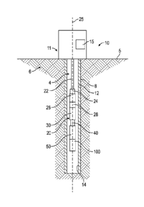
[0027] Referring now to Figures 1, 2, a completion system 10 for completing a
wellbore
4 extending into a subterranean formation 6 is shown. In the embodiment of
Figures 1,
2, wellbore 4 is a cased wellbore including a casing string 12 having a
generally
cylindrical inner surface 14 and which is secured to an inner surface 8 of the
wellbore 4
using cement (not shown). In some embodiments, casing string 12 generally
includes a
plurality of tubular segments coupled together via a plurality of casing
collars.
Completion system 10 includes a surface assembly 11 positioned at a wellsite
13 of
system 10, and a tool string 20 deployable into wellbore 4 from a surface 5
using
surface assembly 11. Surface assembly 11 may comprise any suitable surface
equipment for drilling, completing, and/or operating well 20 and may include,
in some
embodiments, derricks, structures, pumps, electrical/mechanical well control
components, etc. Tool string 20 of completion system 10 may be suspended
within
wellbore 4 from a wireline 22 that is extendable from surface assembly 11.
Wireline 22
comprises an armored cable and includes at least one electrical conductor for
transmitting power and electrical signals between tool string 20 and a control
system or
firing panel 15 of surface assembly 11 positioned at the surface 5.
[0028] In some embodiments, system 10 may further include suitable surface
equipment
for drilling, completing, and/or operating completion system 10 and may
include, for
example, derricks, structures, pumps, electrical/mechanical well control
components,
etc. Tool string 20 is generally configured to perforate casing string 12 to
provide for
fluid communication between formation 6 and wellbore 4 at predetermined
locations to
8
Date Recue/Date Received 2020-08-04
allow for the subsequent hydraulic fracturing of formation 6 at the
predetermined
locations.
[0029] In this embodiment, tool string 20 has a central or longitudinal axis
25 and
generally includes a cable head 24, a casing collar locator (CCL) 26, a direct
connect
sub 28, one or more perforating guns or tools 30, a plug-shoot firing head
(PSFH) 40, a
setting tool 50, and a downhole sealing device or plug 100. Cable head 24 is
the
uppermost component of tool string 20 and includes an electrical connector for
providing electrical signal and power communication between the wireline 22
and the
other components (CCL 26, perforating gun 30, PSFH 40, setting tool 50, etc.)
of tool
string 20. CCL 26 is coupled to a lower end of the cable head 24 and is
generally
configured to transmit an electrical signal to the surface via wireline 22
when CCL 26
passes through a casing collar of casing string 12. In some embodiments, the
signal
transmitted by CCL 26 may be recorded at surface assembly 11 as a collar kick
to
determine the position of tool string 20 within wellbore 4 by correlating the
recorded
collar kick with an open hole log. The direct connect sub 28 is coupled to a
lower end of
CCL 26 and is generally configured to provide a connection between the CCL 26
and
the portion of tool string 20 including perforating gun 30 and associated
tools, such as
the setting tool 50 and downhole plug 100.
[0030] Perforating gun 30 of tool string 20 is coupled to direct connect sub
28 and, as
will be discussed further herein, is generally configured to perforate casing
string 12 and
provide for fluid communication between formation 6 and wellbore 4.
Particularly,
perforating gun 30 may include a plurality of shaped charges that may be
detonated by
one or more electrical signals conveyed by the wireline 22 from the firing
panel 15 of
surface assembly 11 to produce one or more explosive jets directed against
casing
string 12. Perforating gun 30 may comprise a wide variety of sizes such as,
for
example, 2 3/4", 3 1/8", or 3 3/8", wherein the above listed size designations
correspond
to an outer diameter of perforating gun 30. PSFH 40 of tool string 20 is
coupled to a
lower end of perforating gun 30. PSFH 40 couples the perforating gun 30 of the
tool
string 20 to the setting tool 50 and downhole plug 100 and is generally
configured to
pass a signal from the wireline 22 to the setting tool 50 of tool string 20.
PSFH 40 may
also include electrical components to fire the setting tool 50 of tool string
20. In some
9
Date Recue/Date Received 2020-08-04
embodiments, tool string 20 may not include PSFH 40, and instead, perforating
gun 30
may control the operation of setting tool 50.
[0031] In this embodiment, tool string 20 further includes setting tool 50 and
downhole
plug 100, where setting tool 50 is coupled to a lower end of PSFH 40 and is
generally
configured to set or install downhole plug 100 within casing string 12 to
fluidically isolate
desired segments of the wellbore 4. Particularly, setting tool 50 may actuate
downhole
plug 100 from a first or run-in configuration (shown in Figure 1) where fluid
is permitted
to flow across downhole plug 100 to a second or set configuration (shown in
Figure 2)
where the downhole plug 100 sealingly engages the inner surface 14 of casing
string
12. Thus, setting tool 50 may expand an outer diameter of downhole plug 100
when
actuating the downhole plug 100 from the run-in configuration to the set
configuration.
In some embodiments, setting tool 50 may be operated to actuate downhole plug
100
between the run-in and set configurations in response to the transmission of a
firing
signal from firing-panel 15 to setting tool 50.
[0032] With downhole plug 100 in the set configuration, downhole plug 100
divides
wellbore 4 into an uphole portion 7 (shown in Figure 2) extending uphole from
downhole
plug 100 to the surface 5 and a downhole portion 9 (shown in Figure 2)
extending from
downhole plug 100 to a terminal end or toe (not shown in Figures 1, 2) of
wellbore 4. In
the set configuration, fluid configuration may be restricted between the
uphole portion 7
and the downhole portion 4. Following the actuation of downhole plug 100 into
the set
configuration, the perforating gun 30 of tool string 20 may be actuated to
form a plurality
of perforations in casing string 12 through which the formation 6 may be
subsequently
fractured by pressurized fluid pumped into wellbore 4 from the surface 5.
[0033] Referring to Figures 3-9, an embodiment of the downhole plug 100 of the
tool
string 20 of Figures 1, 2 is shown in Figures 3-9. In the embodiment of
Figures 3-9,
downhole plug 100 has a central or longitudinal axis 105 and may generally
include a
mandrel 102, an engagement disk 130, a body lock ring assembly 140, a first
clamping
member 160, an elastomeric member or packer 170, a second clamping member 180,
a
nose cone 200, and a slip assembly 220.
[0034] The mandrel 102 of downhole plug 100 has a first end 102A, a second end
102B,
a central bore or passage 104 defined by a generally cylindrical inner surface
extending
Date Recue/Date Received 2020-08-04
between ends 102A, 102B, and a generally cylindrical outer surface 106
extending
between ends 102A, 102B. In this embodiment, the inner surface of mandrel 102
may
include a frustoconical seat 108 proximal first end 102A that may receive an
obturating
member (e.g., a ball, dart, etc.) for restricting downhole (e.g., in the
direction of second
end 102B from first end 102A) through the central passage 104 of mandrel 102.
For
example, following the actuation of downhole plug 100 into the set
configuration, an
obturating member may be pumped into wellbore 4 and through uphole portion 7
for
seating against seat 108 such that fluid flow through central bore 104 of
mandrel 102 is
restricted, thereby preventing fluid flow from the uphole portion 7 of
wellbore to the
downhole portion 7 thereof. In this embodiment, an expanded diameter portion
or collar
110 is coupled to the outer surface 106 of mandrel 102 at first end 102A, the
collar 110
forming an annular shoulder at first end 102A. Collar 110 includes a plurality
of
circumferentially spaced apertures configured to receive a plurality of
connecting
members (not shown in Figures 3-9) for coupling collar 110 and mandrel 102
with
setting tool 50. Additionally, mandrel 102 includes a plurality of ratchet
teeth 120 that
extend along a portion of outer surface 106.
[0035] Engagement disk 130 of downhole plug 100 is disposed about mandrel 102
and
may have a first end comprising an annular engagement surface 132 configured
to
engage a corresponding annular engagement surface of setting tool 50 for
actuating
downhole plug 100 from the run-in configuration to the set configuration, as
will be
discussed further herein. In the run-in configuration of downhole plug 100,
engagement
surface 132 of engagement disk 130 may be disposed directly adjacent or
contact collar
110.
[0036] In this embodiment, the body lock ring assembly 140 of downhole plug
100 may
comprise a plurality of circumferentially spaced arcuate lock ring segments
142
disposed about mandrel 102, and an annular lock ring retainer 150 disposed
about lock
ring segments 142. Each lock ring segment 142 may include an arcuate inner
surface
that comprises a plurality of ratchet teeth 144. Ratchet teeth 144 may
matingly engage
the ratchet teeth 120 of mandrel 102 to restrict relative axial movement
between lock
ring segments 142 and mandrel 102.
11
Date Recue/Date Received 2020-08-04
[0037] Particularly, the mating engagement between ratchet teeth 144 of lock
ring
segments 142 and ratchet teeth 120 of mandrel 102 prevent lock ring segments
142
from travelling axially towards the first end 102A of mandrel 102, but permits
lock ring
segments 142 to travel axially towards the second end 102B of mandrel 102.
Thus,
ratchet teeth 120, 144 may act as a one-way ratchet permitting relative axial
movement
between mandrel 102 and lock ring assembly 140 in a single direction.
Additionally,
each lock ring segment 142 may include an outer surface that comprises an
arcuate
groove and a generally frustoconical surface 146. Lock ring retainer 150 may
retain
lock ring segments 142 in position about mandrel 102 such that segments 142 do
not
move axially relative to each other.
[0038] First clamping member 160 of downhole plug 100 is generally annular and
is
disposed about mandrel 102 between engagement disk 130 and packer 170. In this
embodiment, first clamping member 160 has a generally cylindrical inner
surface that
may include a first frustoconical surface 162 located proximal a first end
thereof and a
second frustoconical surface 164 extending from a second end thereof.
Additionally, as
will be described further herein, the first frustoconical surface 162 of first
clamping
member 160 may be configured to matingly engage the frustoconical surface 146
of
each lock ring segment 142 when downhole plug 100 is set in wellbore 4.
[0039] Packer 170 of downhole plug 100 is generally annular and disposed about
mandrel 102 between first clamping member 160 and second clamping member 180.
Packer 170 comprises an elastomeric material configured to sealingly engage
the inner
surface 14 of casing string 12 when downhole plug 100 is actuated from the run-
in
configuration to the set configuration. In this embodiment, packer 170
comprises a
generally cylindrical outer surface 172 extending between first and second
ends of
packer 170. Outer surface 172 of packer 170 may include a pair of
frustoconical
surfaces 174 extending from each end of packer 170.
[0040] Second clamping member 180 of downhole plug 100 is generally annular
and is
disposed about mandrel 102 between packer 170 and slip assembly 220. In this
embodiment, second clamping member 180 has a generally cylindrical inner
surface
that may include an inner frustoconical surface 182 extending from a first end
of second
clamping member 180. Additionally, second clamping member 180 may include a
12
Date Recue/Date Received 2020-08-04
generally cylindrical outer surface that includes a plurality of
circumferentially spaced
planar (e.g., flat) surfaces 184 extending from a second end of second
clamping
member 180. Each planar surface 184 extends at an angle relative to the
central axis
105 of downhole plug 100.
[0041] Nose cone 200 of downhole plug 100 is generally annular and is disposed
about
the second end 102B of mandrel 102. Nose cone 200 has a first end 200A, a
second
end 200B opposite first end 200A, a central bore or passage 202 defined by a
generally
cylindrical inner surface 204 extending between ends 200A, 200B, and a
generally
cylindrical outer surface 206 extending between ends 200A, 200B. In this
embodiment,
the inner surface 204 of nose cone 200 includes a connector that releasably or
threadably couples with a connector of mandrel 102 to restrict relative axial
movement
between mandrel 102 and nose cone 200; however, in other embodiments, nose
cone
200 may be coupled to mandrel 102 through various means. In still other
embodiments,
nose cone 200 may be formed integrally with mandrel 102. In this embodiment,
nose
cone 200 may include a plurality of circumferentially spaced protrusions or
notches 208
extending axially from first end 200A of nose cone 200. As will be discussed
further
herein, protrusions 208 of nose cone 200 are configured to interlock with slip
assembly
220 to thereby restrict relative rotation between slip assembly 220 and nose
cone 200.
In other embodiments, nose cone 200 may not include protrusions 208.
[0042] Slip assembly 220 of downhole plug 100 has a central or longitudinal
axis coaxial
with central axis 105 and is generally configured to engage or "bite into" the
inner
surface 14 of casing string 12 when downhole plug 100 is actuated into the set
configuration to couple or affix downhole plug 100 to casing string 12,
thereby restricting
relative axial movement between downhole plug 100 and casing string 12, and
permitting downhole plug 100 to maintain a differential pressure between
uphole portion
7 and downhole portion 9 of wellbore 4. In this embodiment, slip assembly 220
may
comprise a plurality of circumferentially spaced arcuate first slip segments
222 disposed
about mandrel 102, a plurality of circumferentially spaced arcuate second slip
segments
240, and a pair of axially spaced annular retainers 215 each disposed about
the first slip
segments 222 and second slip segments 240. Slip segments 222, 240 are
positioned
alternatingly about the circumference of mandrel 102 such that a first slip
segment 222
13
Date Recue/Date Received 2020-08-04
is positioned between each pair of adjacently disposed second slip segments
240.
Although in this embodiment slip assembly 220 is used with downhole plug 100,
in other
embodiments slip assembly 220 may be used with other downhole sealing devices
other than plugs. Additionally, while in this embodiment downhole plug 100
comprises a
single slip assembly 220, in other embodiments, downhole plug 100 may comprise
two
or more slip assemblies 220.
[0043] As will be described further herein, retainers 215 act to retain the
slip segments
222, 240 of slip assembly 220 in a first or radially inner position relative
central axis 105
corresponding to the run-in configuration of downhole plug 100. As will be
described
further herein, retainers 215 are configured to snap upon actuation of
downhole plug
100 from the run-in configuration to the set configuration to permit the slip
segments
222, 240 of slip assembly 220 to actuate or displace into a second or radially
outer
position relative central axis 105. Although in this embodiment downhole plug
100
comprises retainers 215 for securing slips 222, 240 in the radially inner
position, in other
embodiments, downhole plug 100 may not include retainers 215.
[0044] As shown particularly in Figures 6, 7, each first slip segment 222 of
slip assembly
220 comprises a body 231 having a first end 222A, a second end 222B, and an
inner
surface extending between ends 222A, 222B that may include a planar (e.g.,
flat)
surface 224 extending from first end 222A towards second end 222B. In some
embodiments, the body 227 of each first slip segment 222 may comprise a
dissolvable
material such as a dissolvable magnesium, aluminum, polymer, composite,
plastic, etc.;
however, in other embodiments, the material composition of body 227 may vary.
For
instance, in other embodiments, body 227 may comprise a non-dissolvable
material.
The planar surface 224 of the body 231 of each first slip segment 222 may
extend at a
non-zero angle (e.g., an acute angle) relative to central axis 105 of downhole
plug 100
and may be configured to matingly engage one of the planar surfaces 184 of
second
clamping member 180.
The planar (e.g., flat) interface formed between each
corresponding planar surface 184 of clamping member 180 and each planar
surface
224 of first slip segments 222 may restrict relative rotation between second
clamping
member 180 and first slip segments 222. Additionally, the body 231 of each
first slip
segment 222 may include a pair of opposing lateral sides 223 each extending
from first
14
Date Recue/Date Received 2020-08-04
end 222A and second end 222B of the first slip segment 222. Ends 222A, 222B of
each
first slip segment 222 define an axial length 227 of the first slip segment
222 while
lateral sides 223 define a lateral width 225 of the first slip segment 222.
[0045] In this embodiment, an arcuate outer surface 226 of the body 231 of
each first
slip segment 222 may include a plurality of openings or receptacles each
receiving an
insert or engagement member 228 that matingly engages or couples with the body
231.
Engagement members 228 are configured to engage or bite into the inner surface
14 of
casing string 12 when downhole plug 100 is actuated into the set configuration
to
thereby affix downhole plug 100 to casing string 12 at a desired or
predetermined
location. In this embodiment, engagement members 228 comprise a suitable
material
for engaging with inner surface 14 of casing string 12 during operations. For
example,
engagement members 228 may comprise a ceramic material, 8620 Chrome-Nickel-
Molybdenum alloy, carbon steel, tungsten carbide, cast iron, and/or tool
steel; however,
in other embodiments, engagement members 228 may comprise various materials.
For
example, in other embodiments, engagement members 228 may comprise a
dissolvable magnesium, aluminum, polymer, composite, plastic, etc.
In still other
embodiments, each first slip segment 222 may not include a separately formed
engagement member 228, and instead may include a plurality of engagement
members
formed integrally or monolithically with the body 231 of the first slip
segment 222.
[0046] In this embodiment, each engagement member 228 comprises a generally
cylindrical button having a central or longitudinal axis which extends at a
non-zero angle
relative to the central axis 105 of downhole plug 100. For example, the
central axis of
each engagement member 228 may be oriented in the direction of an upper end of
downhole plug 100 defined by the upper end 102A of mandrel 100. As will be
discussed further herein, in other embodiments, the configuration of each
engagement
member 228 may vary. Additionally, the plurality of engagement members 228 of
each
first slip segment 222 may be oriented in a predefined formation or pattern on
outer
surface 226, such as a diamond formation as shown in Figures 6, 7; however, in
other
embodiments, engagement members 228 may be positioned in various patterns (or
randomly) on outer surface 226. In still other embodiments, each first slip
segment 222
may include only a single engagement member 228.
Date Recue/Date Received 2020-08-04
[0047] In this embodiment, each first slip segment 222 of slip assembly 220
may include
a pocket or receptacle 230 located at the second end 222B which extends into
the inner
surface of the first slip segment 222. The pocket 230 of each first slip
segment 222 is
configured to matingly receive one of the protrusions 208 of nose cone 200 to
form an
interlocking engagement therebetween, thereby restricting relative rotation
between the
first slip segment 222 of slip assembly 220 and nose cone 200. In other
embodiments,
first slip segments 222 may not include pockets 230.
[0048] As shown particularly in Figures 8, 9, each second slip segment 240 of
slip
assembly 220 comprises a body 247 having a first end 240A, a second end 240B,
and
an inner surface extending between ends 240A, 240B that includes a planar
(e.g., flat)
surface 242 extending from first end 240A. In some embodiments, the body 247
of
each second slip segment 240 may comprise a dissolvable material such as a
dissolvable magnesium, aluminum, polymer, composite, plastic, etc.; however,
in other
embodiments, the material composition of body 247 may vary. For instance, in
other
embodiments, body 247 may comprise a non-dissolvable material. The planar
surface
242 of the body 247 of each second slip segment 240 extends at an angle
relative to
central axis 105 of downhole plug 100 and is configured to matingly engage one
of the
planar surfaces 184 of second clamping member 180, similar in manner to the
planar
surface 224 of each first slip segment 222. Additionally, the body 247 of each
second
slip segment 240 includes a pair of opposing lateral sides 241 each extending
from first
end 240A and second end 240B of the second slip segment 240. Ends 240A, 240B
of
each second slip segment 240 define an axial length 245 of the second slip
segment
240 while lateral sides 241 define a lateral width of the second slip segment
240.
[0049] In this embodiment, an arcuate outer surface 244 of the body 247 of
each
second slip segment 240 includes a plurality of openings or receptacles each
receiving
an insert or engagement member 228 that matingly engages or couples with the
body
247. In other embodiments, each second slip segment 240 may not include a
separately formed engagement member 228, and instead may include a plurality
of
engagement members formed integrally or monolithically with the body 247 of
second
slip segment 240. In this embodiment, each second slip segment 240 of slip
assembly
220 may include a pocket or receptacle 246 located at the second end 240B
which
16
Date Recue/Date Received 2020-08-04
extends into the inner surface of the second slip segment 240. The pocket 246
of each
second slip segment 240 is configured to matingly receive one of the
protrusions 208 of
nose cone 200 in a manner similar to the interlocking engagement formed
between the
pocket 230 of each first slip segment 222 and the protrusions 208 of nose cone
200. In
other embodiments, the second slip segments 240 of slip assembly 220 may not
include
pockets 246.
[0050] In this embodiment, each second slip segment 240 may include a pair of
arcuately extending anti-extrusion members 248 positioned at first end 240A
and
extending arcuately or laterally from sides 241 of the body 247 of the second
slip
segment 240. In some embodiments, the anti-extrusion member 248 of each second
slip segment 240 may be integrally or monolithically formed with body 247;
however, in
other embodiments, the anti-extrusion member 248 of each second slip segment
240
may be coupled (e.g., molded, welded, coupled via one or more fasteners, etc.)
to the
second body 247 whereby relative movement between the anti-extrusion member
248
and second body 247 is restricted. Although in this embodiment each second
slip
segment 240 includes a pair of anti-extrusion members 248, in other
embodiments,
each second slip segment 240 may include a single anti-extrusion member 248 or
more
than two anti-extrusion members 248. In this embodiment, each anti-extrusion
member
248 comprises a pair of elongate wings or arms 255 (shown in Figures 8, 9)
positioned
at the first end 240A and extending arcuately in opposing directions and
having a
curved outer surface generally co-planar with outer surface 244 and a planar
(e.g., flat)
inner surface 250 disposed at a non-zero angle to planar surface 242. In this
configuration, inner surfaces 250 of anti-extrusion members 248 are configured
to
matingly engage the planar surfaces 184 of second clamping member 180
positioned
adjacent the planar surface 184 engaged by planar surface 242.
[0051] Each anti-extrusion member 248 includes a terminal end 252 distal the
lateral
side 241 of second slip segment 240 from which the anti-extrusion member 248
projects. A lateral width 249 extending between the terminal ends 252 of the
opposed
anti-extrusion members 248 of each second slip segment 240 defines a maximum
width
of the second slip segment 240 which is greater than width 243 extending
between
lateral sides 241 of the second slip segment 240. Additionally, the lateral
width 249 of
17
Date Recue/Date Received 2020-08-04
anti-extrusion members 248 of each second slip segment 240 is greater than a
maximum width of each first slip segment 222. In some embodiments, the lateral
width
249 of anti-extrusion members 248 is about 100% greater than the maximum width
of
each first slip segment 222; however, in other embodiments, the difference in
lateral
width 249 and the maximum width of each first slip segment 222 may vary.
Further, a
maximum axial length 245 of each second slip segment 240 is greater than a
maximum
axial length 227 of each first slip segment 222 of slip assembly 200.
In this
embodiment, each anti-extrusion member 248 includes an anti-extrusion or
engagement surface 254 configured to slidably engage the first end 222A of an
adjacently positioned first slip segment 222, as will be discussed further
herein.
[0052] Referring briefly to Figures 14-18, another embodiment of a downhole
sealing
device or plug 300 is shown. Downhole plug 300 may be used in lieu of, or in
combination with, downhole plug 100 shown in Figures 2-13 as part of a tool
string (e.g.,
tool string 20). Additionally, downhole plug 300 includes features in common
with
downhole plug 100, and shared features are labeled similarly. Particularly,
downhole
plug 300 is similar to downhole plug 100 described above except that downhole
plug
300 includes a slip assembly 310 comprising a plurality of circumferentially
spaced
arcuate first slip segments 312 disposed about the mandrel 102 of downhole
plug 300,
and a plurality of circumferentially spaced arcuate second slip segments 320
also
disposed circumferentially about mandrel 102. Slip segments 312, 320 are
positioned
alternatingly about the circumference of mandrel 102 such that a first slip
segment 312
is positioned between each pair of adjacently disposed second slip segments
320.
[0053] As shown particularly in Figures 15, 16, first slip segments 312 of
slip assembly
310 share features in common with the first slip segments 222 of slip assembly
220
while second slip segments 320 share features in common with second slip
segments
240, and shared features are labeled similarly. Particularly, each first slip
segment 312
comprises a body 313 having a first end 312A, a second end 312B, a pair of
opposing
lateral sides 314, and a radially outer surface 316 (relative a central or
longitudinal axis
305 of downhole plug 300) extending arcuately between the pair of sides 314.
The
outer surface 316 of the body 313 of each first slip segment 312 may include a
plurality
of grooves extending laterally between sides 314, where each longitudinal
groove
18
Date Recue/Date Received 2020-08-04
receives an engagement member 318 extending arcuately about central axis 305.
Engagement members 318 are configured to engage or bite into the inner surface
14 of
casing string 12 when downhole plug 300 is actuated into the set configuration
to
thereby affix downhole plug 300 to casing string 12 at a desired or
predetermined
location. Each engagement member 318 may be formed from a material similar to
that
comprising engagement members 228 described above. Thus, instead of comprising
cylindrical buttons as with engagement members 228, engagement members 318
comprise arcuate blades which may be arranged in rows along a length of the
first slip
segment 310.
[0054] As shown particularly in Figures 17, 18, each first slip segment 320 of
slip
assembly 320 comprises a body 322 having a first end 320A, a second end 320B,
a pair
of opposing lateral sides 324, and a radially outer surface 326 (relative a
central or
longitudinal axis 305 of downhole plug 300) extending arcuately between the
pair of
sides 324. The outer surface 326 of the body 322 of each first slip segment
320 may
similarly include a plurality of grooves extending laterally between sides
324, where
each longitudinal groove receives one of the engagement members 318.
[0055] Referring to Figures 1-4, 10-13, as described above, downhole plug 100
is
pumped downhole though wellbore 4 along with the other components of tool
string 20.
As tool string 20 is pumped through wellbore 4, the position of tool string 20
in wellbore
4 is monitored at the surface via signals generated from CCL 26 and
transmitted to the
surface using wireline 22. Once tool string 20 is disposed in a desired
location in
wellbore 4, one or more of perforating guns 30 may be fired to perforate
casing 12 at
the desired location and setting tool 50 may be fired or actuated to actuate
downhole
plug 100 from the run-in configuration (shown in Figures 1, 4, 10, and 11) to
the set
configuration (shown in Figures 12, 13).
[0056] Particularly, setting tool 50 includes an inner member or mandrel (not
shown)
that moves axially relative to an outer member or housing of setting tool 50
upon the
actuation of tool 50. The mandrel of setting tool 50 is coupled to mandrel 102
of
downhole plug 100 such that the movement of the mandrel of setting tool 50
pulls
mandrel 102 uphole (e.g., towards setting tool 50). Additionally, the outer
member of
setting tool 50 contacts engagement surface 132 of engagement disk 130 to
prevent
19
Date Recue/Date Received 2020-08-04
disk 130, clamping members 160, 180, packer 170, and slip assembly 220 from
travelling in concert with mandrel 102, thereby providing relative axial
movement
between mandrel 102 and disk 130, clamping members 160, 180, packer 170, and
slip
assembly 220.
[0057] As mandrel 102 travels uphole towards setting tool 50, the first end
200A of nose
cone 200 and the second end 130B of engagement disk 130 apply an axially
compressive force against clamping members 160, 180, packer 170, and slip
assembly
220. In response to the application of the compressive force, slip segments
222, 240
are forced radially outward towards casing string 12 from the radially inner
position as
planar surfaces 184 of second clamping member 180 slide along the planar
surfaces
224, 242 of slip segments 222, 240, respectively, snapping retainers 215. Slip
segments 222, 240 continue to travel radially outwards until engagement
members 228
contact and couple to the inner surface 14 of casing string 12, disposing slip
segments
222, 240 in the radially outer position and locking downhole plug 100 to
casing string 12
at the desired location in wellbore 4. Additionally, each end of packer 170 is
compressed via contact between frustoconical surfaces 174 of packer 170 and
frustoconical surfaces 164, 182 of clamping members 160, 180, respectively.
The
axially directed compressive force applied to packer 170 forces the outer
surface 172 of
packer 170 into sealing engagement with the inner surface 14 of casing string
12. With
outer surface 172 of packer 170 sealing against the inner surface 14 of casing
string 12,
the only fluid flow permitted between the uphole portion 7 and the downhole
portion 9 of
wellbore 4 across downhole plug 100 is permitted via passage 104 of mandrel
102
when passage 104 is unobstructed.
[0058] As the outer surface 172 of packer 170 engages the inner surface 14 of
casing
string 12, pressure between outer surface 172 and inner surface 14 urges a
portion of
packer 170 in an axial direction relative second clamping member 180 towards
nose
cone 200. In other words, pressure applied to the outer surface 172 of packer
170 by
the inner surface 14 of casing string 12 acts to extrude a portion of packer
170 axially
between second clamping member 180 and casing string 12. The anti-extrusion
members 248 of the second slip segments 240 of slip assembly 220 act to limit
the
amount of packer 170 that is axially extruded between second clamping member
180
Date Recue/Date Received 2020-08-04
and casing string 12, thereby maintaining the sealing integrity between packer
170 and
casing string 12 required for hydraulically fracturing the formation 6.
[0059] As shown particularly in Figures 10, 11, when downhole plug 100 is in
the run-in
configuration, the terminal end 252 of each anti-extrusion member 248 is
positioned
directly adjacent or contacts the terminal end 252 of an anti-extrusion member
248 of an
adjacently positioned second slip segment 240. Particularly, a second overlap
251
(shown in Figure 11) extends arcuately between each anti-extrusion member 248
and
each first slip segment 222. In this arrangement, the first end 222A of each
first slip
segment 222 is substantially or entirely engaged or covered by the engagement
surfaces 254 of the anti-extrusion members 248 of adjacently positioned second
slip
segments 240. As downhole plug 100 actuates from the run-in configuration into
the set
configuration and slip segments 222, 240 are displaced radially outwards into
the
radially outer position and towards the inner surface 14 of casing string 12,
the
engagement surfaces 254 of anti-extrusion members 248 slide against the first
ends
222A of first slip segments 222.
[0060] With downhole plug 100 disposed in the set configuration as shown in
Figures
12, 13, at least a portion of each anti-extrusion member 248 arcuately
overlaps at least
a portion of the first end 222A of an adjacently positioned first slip segment
222.
Particularly, a second overlap 253 (shown in Figure 13) extends arcuately
between
each anti-extrusion member 248 and each first slip segment 222 when slip
segments
222, 240 are in the radially outer position. In this configuration, material
of packer 170
is prevented from entering arcuate gaps 260 (shown in Figure 12) that form
radially
between adjacently positioned slip segments 222, 240 as downhole plug 100
actuates
into the set configuration and slip segments 222, 240 expand radially
outwards. Thus, a
circumferential spacing between each slip segment 222, 240 increases when slip
segments 222, 240 are actuated form the radially inner position to the
radially outer
position. Additionally, with slip segments 222, 240 in the radially outer
position directly
adjacent the inner surface 14 of casing string 12, material of packer 170 is
prevented
from being extruded radially between slip segments 222, 240 and casing string
12. In
other words, the flow of material of packer 170 is blocked by the first ends
222A, 240A
21
Date Recue/Date Received 2020-08-04
of slip segments 222, 240, respectively, thereby maintaining the integrity of
the annular
seal formed between packer 170 and casing string 12.
[0061] Further, in addition to preventing or mitigating axial extrusion of
packer 170 and
loss of seal integrity between packer 170 and casing string 12, anti-extrusion
members
248 of second slip segments 240 eliminate the need for an additional back-up
ring
separate from slip segments 222, 240 and nose cone 200, thereby minimizing the
number of components comprising slip assembly 220, the overall cost associated
with
manufacturing downhole plug 100, and the total time required for assembling
downhole
plug 100. Additionally, by simplifying the assembly of downhole plug 100 by
eliminating
the need for a separate back-up ring, anti-extrusion members 248 reduce the
likelihood
of misassembly of downhole plug 100 that may prevent downhole plug 100 from
operating as intended.
[0062] Following the coupling of slip segments 202 with casing string 12 and
the sealing
of packer 170 against casing string 12 (shown in Figure 14), setting tool 50
may be
disconnected from downhole plug 100, allowing setting tool 50 and the other
components of tool string 20 to be retrieved to the surface of wellbore 4,
with downhole
plug 100 remaining at the desired location in wellbore 4. Once setting tool 50
is
released from downhole plug 100, contact between frustoconical surface 162 of
first
clamping member 160 and the frustoconical surfaces 146 of lock ring segments
142
applies an axial and radially inwards force against each lock ring segment
142.
However, engagement between ratchet teeth 144 of lock ring segments 142 and
ratchet
teeth 120 of mandrel 102 prevent lock ring segments 142 from moving axially
uphole
relative to mandrel 102. With lock ring segments 142 prevented from travelling
uphole
in the direction of the upper end 102A of mandrel 102, downhole plug 100 is
held in the
set configuration. After tool string 20 has been retrieved from the wellbore
4, a ball or
dart may be pumped into and through wellbore 4 until the ball lands against
seat 108 of
mandrel 102. With the ball seated on seat 108 of mandrel 102, fluid flow
through
passage 104 of mandrel 102 is restricted which, in conjunction with the seal
formed by
packer 170 against the inner surface 14 of casing string 12, seals the portion
of wellbore
4 extending downhole from downhole plug 100 from the surface. Thus, additional
fluid
pumped into wellbore 4 from the surface is then directed through the
perforations
22
Date Recue/Date Received 2020-08-04
previously formed in casing string 12 by one or more of the perforating guns
30, thereby
hydraulically fracturing the formation 6 at the desired location in wellbore
4.
[0063] While exemplary embodiments have been shown and described,
modifications
thereof can be made by one skilled in the art without departing from the scope
or
teachings herein. The embodiments described herein are exemplary only and are
not
limiting. Many variations and modifications of the systems, apparatus, and
processes
described herein are possible and are within the scope of the disclosure
presented
herein. For example, the relative dimensions of various parts, the materials
from which
the various parts are made, and other parameters can be varied. Accordingly,
the scope
of protection is not limited to the embodiments described herein, but is only
limited by
the claims that follow, the scope of which shall include all equivalents of
the subject
matter of the claims. Unless expressly stated otherwise, the steps in a method
claim
may be performed in any order. The recitation of identifiers such as (a), (b),
(c) or (1),
(2), (3) before steps in a method claim are not intended to and do not specify
a
particular order to the steps, but rather are used to simplify subsequent
reference to
such steps.
23
Date Recue/Date Received 2020-08-04