Note: Descriptions are shown in the official language in which they were submitted.
CA 03089385 2020-07-22
WO 2019/148034 PCT/US2019/015285
Title: Hinged Connector
Background of the Invention
[0001] The present invention provides a connection between two structural
members by
means of a connector and fasteners. The connector is provided with a hinge so
that the
structural members can be joined and then shipped to a job site in a collapsed
or folded
arrangement. When the structural members arrive at the site and are ready to
be erected
they are moved to a second, unfolded position.
[0002] Hinged connectors are well known in the art and are particularly
suitable for large
trusses that need to be collapsed during shipping. The hinge joints are used
at
connections between members in the truss where it would be beneficial to
connect the
members at the factory where the truss is made but connect the members in such
a
manner that they can rotate with respect to each other so that the truss can
be shipped
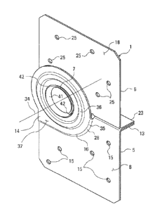
in a collapsed state. US Patent 5,553,961, invented by Michael M. Olden and
which
issued in 1996 teaches a hinged connector that is useful for transporting
trusses in a
collapsed state. US Patent 5,553,961 was considered by its inventor to be an
improvement patent over US Reissue Patent 31,234 which reissued May 10, 1983.
[0003] The present invention improves upon the prior art by providing a
connector that
is inexpensive to make and install yet it is strong and can be installed in
pairs on both
sides of the structural members to be connected.
Summary of the Invention
[0004] It is an object of the present invention to provide a hinged connector
that can
make a strong connection between the structural members it connects while
allowing
the structural members to pivot with respect to each other. The hinged
connector is
1
CA 03089385 2020-07-22
WO 2019/148034 PCT/US2019/015285
used to attach two generally coplanar first and second structural members
while allowing
for pivotal movement of the structural members in the plane of the structural
members
about an axis that is transverse or perpendicular to the plane in which the
structural
members rotate.
[0005] It is a further object of the present invention to provide a connector
where the
fastener openings are arranged so that the connector can be used in pairs with
the
fasteners not interfering with each other.
[0006] It is further object of the invention to provide a connector where the
members or
plates that make up connector are formed with extensions that are joined in a
manner to
create a hinge. The extension of one of the members is provided with an offset
so that
the extensions can closely overlap to make for a strong connection. The
connector is
preferably made from sheet metal that is cold-formed such that the offset is
formed from
a pair of angled offsetting bends between the plate and the extension that has
the hinge.
[0007] It is a further object of the invention to provide a connector where
the pivotably
connected members are formed with indexing flanges that engage edge surfaces
of the
structural members they connect to help properly position the connector or
connectors.
This can be particularly important when the hinged connectors are used in
aligned pairs
on opposed surfaces of the structural members. It is important that the axes
of rotation
of the hinges be aligned.
Brief Description of the Drawings
[0008] Fig. 1 is a front perspective view of the connector of the present
invention.
[0009] Fig. 2 is a back perspective view of the connector of Fig. 1.
2
CA 03089385 2020-07-22
WO 2019/148034 PCT/US2019/015285
[0010] Fig. 3 is a front perspective view of the connector of the present
invention with
the members of the connector rotated about the hinge.
[0011] Fig. 4 is front view of the connector of Fig. 1.
[0012] Fig. 5 is a back view of the connector of Fig. 1.
[0013] Fig. 6 is a left side view of the connector of Fig. 1.
[0014] Fig. 7 is a right side view of the connector of Fig. 1.
[0015] Fig. 8 is a top view of the connector of Fig. 1.
[0016] Fig. 9 is a bottom view of the connector of Fig. 1.
[0017] Fig. 10 is a cross-sectional, top view of the connector of Fig. 1 taken
along the
view line shown in Fig. 4.
[0018] Fig. 11 is a side view of a connection made according to the present
invention
with the structural members connected by the connecter disposed in a collapsed
state.
[0019] Fig. 12 is a side view of a connection made according to the present
invention
with the structural members connected by the connecter disposed in their final
configuration when installed.
[0020] Fig. 13 is a perspective view of the connection shown in Fig. 12.
[0021] Fig. 14 is a perspective view of the connection shown in Fig. 13 with a
second
connector attached to the opposite faces of the structural members.
3
CA 03089385 2020-07-22
WO 2019/148034 PCT/US2019/015285
[0022] Fig. 15 is a side view of the connection shown in Fig. 15, except that
a second
connector is provided on the opposite sides of the structural members. The
fasteners
and the openings in the connector on the opposed sides are shown in dotted
lines.
Detailed Description of the Invention
[0023] As shown in Figs. 11 and 12, according to the present invention, the
hinged
connector 1 is attached to first structural member 2 and a second structural
member 3.
The connector 1 is attached to the first and second structural members 2 and 3
with
fasteners 4. The preferred fasteners 4 are nails, but other fasteners such as
screws or
nail prong teeth may be used. The preferred connector 1 of the present
invention is
formed from overlapping base and top members 5 and 6 which are preferably made
from
sheet metal blanks. The overlapping members 5 and 6 are connected at a hinge
7. The
connector, including the hinge, is preferably cold-formed from the sheet metal
blanks.
[0024] As shown in Fig. 1, the connector 1 consists of a substantially planar
base
member 5 adapted to be connected to the first structural member 2. The base
member 5
is formed with opposed front and back surfaces 8 and 9. The back surface 9
interfaces
with the attachment surface 10 of the first structural member 2. The first
structural
member 2 can also have an adjoining edge surface 11 that is disposed
orthogonally to
the attachment surface 10. The attachment surface 10 and the edge surface 11
meet at
an edge 12. The base member 5 can also be formed with an indexing flange 13
that is
disposed orthogonally to the generally planar base member 5. The indexing
flange 13 is
designed to interface with the adjoining edge surface 11 and thereby position
the
fasteners 4 and the base member 5 with respect to the first structural member
2. The
base member 5 is also formed with an offset extension 14 which is adapted to
pivotally
connect to a planar extension 24 that is connected to the top member 6.
Preferably, the
base member 5 is provided with fastener openings 15.
4
CA 03089385 2020-07-22
WO 2019/148034 PCT/US2019/015285
[0025] As shown in Fig. 1, the connector 1 also consists of a substantially
planar top
member 6 adapted to be connected to the second structural member 3. The top
member
6 is formed with opposed front and back surfaces 18 and 19. The back surface
19
interfaces with the attachment surface 20 of the second structural member 3.
The
second structural member 3 can also have an adjoining edge surface 21 that is
disposed
orthogonally to the attachment surface 20. The attachment surface 20 and the
edge
surface 21 meet at an edge 22. The top member 6 can also be formed with an
indexing
flange 23 that is disposed orthogonally to the generally planar top member 6.
The
indexing flange 23 is designed to interface with the adjoining edge surface 21
and
thereby position the fasteners 4 and the top member 6 with respect to the
second
structural member 3. Preferably, the top member 6 is provided with fastener
openings
25. As shown and described the extension of the base member is offset from the
plane
of the base member and the extension of the top member lies in the plane of
the top
member, but the extension of the top member could just as easily be offset
form the
plane of the top member and the extension of base member could lie in the
plane of the
base member.
[0026] As shown in Figs. 3 and 10, the hinge 7 that connects the members 5 and
6 and
allows the members to pivot with respect to each other can be formed in the
following
manner. The offset extension 14 of the base member 5 extends generally
parallel to the
base member 5, although it is offset from the plane of the base member 5 by a
stepped
juncture 16 where it is connected to the base member 5. The offset extension
14 has an
inside face 17 and an outside face 37. The planar extension 24 is
substantially planar
and extends in line with the top member 6. The planar extension 24 has an
inside face
27 and an outside face 47. The inside face 17 of the offset extension 14
overlies and
interfaces with the outside face 47 of the planar extension 24.
[0027] The offset extension 14 is formed with a circular opening 30 and the
planar
extension 24 is formed with a corresponding circular opening 40. Preferably,
the
corresponding circular opening 29 is at least partially provided with one or
more annular
CA 03089385 2020-07-22
WO 2019/148034 PCT/US2019/015285
flanges 41 which project upwardly from the outside face 47 of the planar
extension 24.
If the entire opening is not circumscribed then at least a pair of opposed
portions of the
corresponding circular opening 40 are provided with one or more annular
flanges 41.
More preferably three or more portions of the circular opening 40 at intervals
around the
perimeter of the corresponding circular opening 40 are provided with one or
more
annular flanges 41. Most preferably the entire opening 40 is provided with one
continuous annular flange 41. To form the hinge and join the two members 5 and
6
together, the offset extension 14 is placed over the planar extension 24 with
the annular
flange 41 of the corresponding circular opening 40 in the planar extension 24
being
inserted through the circular opening 30 in the offset extension 14. The upper
portion 42
of the annular flange 41 is then deformed to bend over an edge 32 of circular
opening
30 in the offset extension 14. The bent upper portion 42 of the annular flange
41
extends radially outwardly and overlies the outside face 18 of the offset
extension 14,
connecting the two members 5 and 6 together. When connected in this manner,
the
extensions 14 and 24 can rotate with respect to each other around an axis 34
that is
disposed orthogonally to the overlapping extensions 14 and 24. While the
offset
extension 14 has been described as being connected to the base member 5, the
offset
extension could extend from the top member 6 and the planar extension could be
part of
the base member 5. The annular flange 41 has been described, according the
preferred
embodiment, as projecting upwardly from the outside face 28 of the planar
extension 24
such that the annular flange 41 extends away from the attachment surfaces 10
and 20
of the first and second 2 and 3 structural members. This arrangement of the
members is
preferred so as to allow the first and second structural members 2 and 3 to
rotate with
respect to each other without rubbing against the annular flange 41 of the
hinge 7, but
the annular flange 41 could project toward the attachment surfaces from the
offset
flange 14.
[0028] As noted above, the offset extension 14 is connected to the base member
5 at a
stepped juncture 16. The stepped juncture 16 extends away from the attachment
surfaces 10 and 20 of the first and second structural members 2 and 3. The
stepped
6
CA 03089385 2020-07-22
WO 2019/148034 PCT/US2019/015285
juncture 16 lifts the offset extension 14 approximately the thickness of the
planar
extension 24 away from the attachment surfaces 10 and 20 of the first and
second
structural members 2 and 3.
[0029] The stepped juncture 16 of the offset extension 14 is preferably formed
with a
curved portion 35 that conforms substantially to the curved edge portion 28 of
the
extension 24 of the top member. The curved portion 28 is an arc of a circle
having its
radius centered on the axis 34 of the hinge 7.
[0030] The extensions 14 and 24 are preferably offset with respect to the base
and top
members 5 and 6.
[0031] As discussed above, preferably, the base member 5 is provided with
fastener
openings 15, and the top member 6 is provided with fastener openings 25. Each
of the
base member 5 and the top member 6 is preferably formed with five fastener
openings
15 or 25. To help prevent splitting of the first and second structural members
2 and 3
when they are made from wood, the openings 15 in the base member 5 are
staggered
with respect to each other and the openings 25 in the top member 6 are
staggered with
respect to each other.
[0032] As shown in Fig. 15, the fasteners openings 15 in the base member 5 are
arranged so that if a line was drawn between the centers of two of the
fastener
openings 15 in the base member 5 that same line would not intersect with any
of the
centers of the other fastener openings 15. Similarly, the fastener openings 25
in the top
member 6 are arranged so that if a line was drawn between two of the fastener
openings 25 in the top member 6 that same line would not intersect with any of
the
centers of the other fastener openings 25.
7
CA 03089385 2020-07-22
WO 2019/148034 PCT/US2019/015285
[0033] To also help prevent splitting when wood structural members 2 and 3 are
used,
any line drawn through the centers of two of the fastener openings 15 in the
base
member 5 would not be parallel to the long axis 51 or 52 of the first or
second structural
member 2 or 3 to which the base member 5 is attached. Similarly, any line
drawn
through the centers of two of the fastener openings 25 in the top member 6
would not
be parallel to the long axis 51 or 52 of the first or second structural member
2 or 3 to
which the top member 6 is attached. As shown in Fig. 15, preferably the planar
indexing
flanges 13 and 23 are disposed parallel with the long axes 51 and 52 of the
first and
second structural members 2 and 3, and the long axes 51 and 52 are disposed
parallel
with the adjoining edges surfaces 11 and 21.
[0034] The indexing flanges 13 and 23 are substantially aligned with a
diameter through
the circular openings 30 and 40 in the extensions 14 and 24. When the
connector 1 is in
a folded position the indexing flange 23 of the top member 6 contacts the
indexing
flange 13 of the base member 13.
[0035] As shown in Fig. 14, the first structural member 2 is also formed with
a second
opposed attachment surface 110, and the second structural member 3 is also
formed
with a second opposed attachment surface 120. The adjoining edge surface 11
connects
the attachment surfaces 10 and 110 of the first structural member 2, and the
adjoining
edge surface 21 connects the attachment surfaces 20 and 120 of the second
structural
member 3.
[0036] A second connector 101 is attached to the opposed attachment surfaces
110
and 120 of the first and second structural members 2 and 3. The second
connector 101
shown in Fig. 14 is identical to the connector 1 shown in Fig. 14, except that
the
second connector 101 is disposed upside down with the base member 105 being
connected to the second structural member 3 and the top member 106 being
connected
to the first structural member 2. The second connector 101 has a hinge 107,
and the
base member 105 is formed with fastener openings 115 that are arranged in the
same
8
CA 03089385 2020-07-22
WO 2019/148034 PCT/US2019/015285
positions as the fastener openings 15 of the base member 5 of the first
connector 1, and
the top member 106 of the second connector 101 is formed with fastener
openings 125
that are arranged in the same positions as the fastener openings 25 of the top
member 6
of the first connector 1.
[0037] When the first or hinged connector 1 and an identical second connector
101 are
installed in a pair with the second connector 101 being installed up-side down
with
respect to the first connector 1 to connect first and second member 2 and 3,
the hinges
7 and 107 of the connectors will need to be aligned for the pivoting action to
work
properly. When installed appropriately as described, the base member 5 of the
first
connector 1 and the top member 106 of the second connector 101 will both be
attached
to the first structural member 2 with the base member 5 and the top member 106
overlying each other on the opposite surfaces 10 and 110 of the first
structural member
2, and with the fastener openings 15 of the base member 5 of the first
connector 1
being staggered with respect to the fastener openings 125 of the top member
106 of
the second connector 101. At the same time, the base member 105 of the second
connector 101 and the top member 6 of the first connector 1 will both be
attached to
the second structural member 3 with the base member 105 and the top member 6
overlying each other on the opposite surfaces 20 and 220 of the second
structural
member 3, and with the fastener openings 115 of the base member 105 of the
second
connector 101 being staggered with respect to the fastener openings 25 of the
top
member 6 of the first connector 1.
[0038] The connector is installed by placing the first and second structural
member 2
and 3 in their installed positions. The connector 1 is then placed in
interfacing
engagement with the attachment surfaces 10 and 20 of the first and second
members 2
and 3 with the indexing flanges 13 and 23 engaging the edge surfaces 11 and
21.
Fasteners 4 are then driven through the openings 15 and 25 in the base and top
members 5 and 6 to attach the connector 1 to the first and second members 2
and 3. If
a second connector 101 is used, the first and second structural members 2 and
3 can be
9
CA 03089385 2020-07-22
WO 2019/148034 PCT/US2019/015285
turned over and the second connector 101 is installed similarly with the base
member
105 connected to the structural member that is attached to the top member 6 of
the
first connector 1.
[0039] As shown in Fig. 1, the offset extension 14 of the base member 5 is
formed with
one or more embossments 36 with the one or more embossments 36 circumscribing
or
partially circumscribing the opening 30 in the offset extension. Preferably
the
embossment 36 is a single, continuous member that completely circumscribes the
opening 30. The embossment 36 preferably projects away from the first and
second
structural members 2 and 3.