Note: Descriptions are shown in the official language in which they were submitted.
RAILWAY VEHICLE, COUPLER, AND COUPLER BODY THEREOF
[0001]
FIELD
[0002] The present application relates to the technical field of railway
transportation,
and in particular to a railway vehicle, a coupler and a coupler body thereof.
BACKGROUND
[0003] The coupler is one of the most basic and most important parts of the
railway
vehicle. It is installed at two ends of the vehicle and is used to connect two
adjacent
vehicles and transmit the longitudinal force of the train. There are many
kinds of couplers,
but the most widely used coupler is articulated coupler. As shown in Figure 1,
an
articulated coupler includes a coupler body 03, a coupler knuckle 01, a
coupler lock, a
coupler knuckle push member, a coupler knuckle pin 02 and other components.
The
coupler knuckle 01 is rotatable around the coupler knuckle pin 02 to realize
opening and
locking of the coupler. The main load-bearing parts inside the coupler are a
traction
platform of the coupler knuckle 01 and a traction platform of the coupler body
03. As
shown in Figure 2, two couplers are hitched to connect two adjacent vehicles.
[0004] At present, the fracture of the coupler mainly occurs under the tensile
working
condition. The main load-bearing parts of the coupler are the traction
platform of the
coupler knuckle 01 and the traction platform of the coupler body 03. As shown
in Figures
3 and 4, the coupler knuckle 01 is provided with an upper traction platform, a
lower
traction platform and a lock surface 0 lb. As shown in Figures 5 and 6, the
coupler body is
provided with an upper traction platform, a lower traction platform and a lock
chamber
- 1 -
Date recue / Date received 2021-12-14
CA 03089797 2020-07-28
03c. As shown in Figure 7, when the coupler knuckle is engaged with the
coupler body,
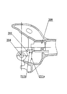
the upper traction platform 01a of the coupler knuckle abuts against the upper
traction
platform 03a of the coupler body, the lower traction platform Old of the
coupler knuckle
abuts against the lower traction platform 03e of the coupler body, and then an
upper
traction surface Olc of the coupler knuckle contacts and abuts against an
upper traction
surface 03b of the coupler body, and a lower traction surface Ole of the
coupler knuckle
contacts and abuts against the lower traction surface 03e of the coupler body
to realize
load bearing. When the coupler lock is in contact with the lock surface 0 lb
of the coupler
knuckle 01, the coupler lock can restrict the coupler knuckle 01 from rotating
around the
coupler knuckle pin 02 to cause the coupler to be in a locked state. When the
coupler lock
is moved into the lock chamber 03c, the coupler knuckle 01 can rotate around
the coupler
knuckle pin 02 to cause the coupler to be in an unlocked state.
[0005] It can be seen from Figures 5 and 6 that the upper traction platform
03a and the
lower traction platform 03e of the coupler body are closer to the lock chamber
03c. After
the coupler knuckle 01 is engaged and connected with the coupler body 03, the
structure
changes abruptly at edges, close to the lock chamber 03c, of the contact area
between the
upper traction platform Ola of the coupler knuckle and the upper traction
platform 03a of
the coupler body and the contact area between the lower traction platform Old
of the
coupler knuckle and the lower traction platform 03d of the coupler body. As a
result, the
stress is more concentrated at the roots of the upper and lower traction
platforms of the
coupler body close to the lock surface, which easily causes the roots of the
upper and
lower traction platforms of the coupler body to break, reduces the service
life of the
coupler body, increases the replacement and maintenance cost of the coupler,
and affects
the nmning safety of the train.
[0006] In summary, how to effectively prolong the service life of the coupler
body and
reduce the maintenance cost of the coupler is an urgent problem to be solved
by those
skilled in the art.
SUMMARY
[0007] In view of this, the first object of the present application is to
provide a coupler
body whose structural design can effectively prolong the service life of the
coupler body
- 2 -
Date Recue/Date Received 2020-07-28
CA 03089797 2020-07-28
and reduce the maintenance cost of the coupler. The second object of the
present
application is to provide a coupler including the coupler body and a railway
vehicle
including the coupler.
[0008] In order to achieve the first object, the following technical solutions
are provided
according to the present application.
[0009] A coupler body includes an upper traction platform, a lower traction
platform, a
lock chamber and a pin hole. A traction surface of the upper traction platform
and/or the
lower traction platform is divided into a contact area and an avoidance area
along a
direction of approaching the lock chamber, an extension surface of one end of
the contact
area close to the lock chamber is defined as M2, and the avoidance area is
located on one
side of the M2 surface close to the pin hole.
[0010] Preferably, in the coupler body, a first end of the avoidance area is
connected
with the contact area and a second end of the avoidance area is far away from
the contact
area. The direction from left to right and perpendicular to the axis of the
pin hole is
defined as the first extension direction. The front side of the coupler body
is used for
engaging with a coupler knuckle. An extension distance from the first end to
the second
end of the avoidance area along the first extension direction is defined as
L2, and
6 Omm>L2>lOmm.
[0011] Preferably, in the coupler body, the contact area is a curved surface.
[0012] Preferably, in the coupler body, the contact area is an arc surface and
protrudes
away from the pin hole.
[0013] Preferably, in the coupler body, the avoidance area is specifically an
inner wall of
a groove provided on the traction surface of the upper traction platform
and/or the lower
traction platform.
[0014] Preferably, in the coupler body, the avoidance area is a curved
surface.
[0015] Preferably, in the coupler body, each traction surface of the upper
traction
platform and the lower traction platform is divided into the contact area and
the avoidance
area along the direction of approaching the lock chamber, an extension surface
of one end
of the contact area close to the lock chamber is defined as M2, and the
avoidance area is
located on one side of the M2 surface close to the pin hole; and
- 3 -
Date Recue/Date Received 2020-07-28
CA 03089797 2020-07-28
the avoidance area of the upper traction platform and the avoidance area of
the
lower traction platform are symmetrically arranged.
[0016] Preferably, in the coupler body, the coupler knuckle is cut along a
vertical plane
perpendicular to a tangent plane of an impact surface of an upper impact
platform or
along a vertical plane perpendicular to a tangent plane of a traction surface
of an upper
pin-protecting flange of the coupler body to obtain a section I of the impact
surface of the
upper impact platform and a section J of the impact surface of the upper pin-
protecting
flange, wherein the minimum horizontal distance between the section I and the
section J
is defined as f, and 15mm < f < 30mm; and/or,
[0017] the coupler knuckle is cut along a vertical plane perpendicular to a
tangent plane
of an impact surface of a lower impact platform or along a vertical plane
perpendicular to
a tangent plane of a traction surface of a lower pin-protecting flange of the
coupler body
to obtain a section K of the impact surface of the lower impact platform and a
section M
of the impact surface of the lower pin-protecting flange, wherein the minimum
horizontal
distance between the section K and the section M is defined as g, and 15mm < g
< 30mm.
[0018] Preferably, in the coupler body, the coupler knuckle is cut along a
vertical plane
perpendicular to a tangent plane of the inner wall of the pin hole or along a
vertical plane
perpendicular to the tangent plane of the traction surface of the upper pin-
protecting
flange to obtain a section N of the inner wall of the pin hole and a section 0
of the impact
surface of the upper pin-protecting flange, wherein the minimum horizontal
distance
between the section N and the section 0 is defined as h, and 15mm < h < 30mm;
and/or,
the coupler knuckle is cut along a vertical plane perpendicular to the tangent
plane of the inner wall of the pin hole or along a vertical plane
perpendicular to the
tangent plane of the traction surface of the lower pin-protecting flange to
obtain a
section P of the inner wall of the pin hole and a section Q of the impact
surface of the
lower pin-protecting flange, wherein the minimum horizontal distance between
the
section P and the section Q is defined as i, and 15mm < i < 30mm.
[0019] A coupler includes a coupler knuckle and a coupler body, wherein the
coupler
body is the coupler body described in any one of the above.
[0020] A railway vehicle includes a coupler, and the coupler is the coupler as
described
- 4 -
Date Recue/Date Received 2020-07-28
CA 03089797 2020-07-28
above.
[0021] When the coupler body provided by the present application is engaged
with the
coupler knuckle, the traction surface of the upper traction platform of the
coupler body
contacts and abuts against the traction surface of the upper traction platform
of the
coupler knuckle, and the traction surface of the lower traction platform of
the coupler
body contacts and abuts against the traction surface of the lower traction
platform of the
coupler knuckle, and the traction platform of the coupler body is located at
one side of the
corresponding traction platform of the coupler knuckle close to the pin hole.
As the upper
traction platform and/or the lower traction platform of the coupler body is
provided with
the avoidance area which is located at one side of the extension surface of
the contact area
close to the pin hole, a gap is provided between the avoidance area of the
traction surface
of the upper traction platform and/or the lower traction platform of the
coupler body and
the traction surface of the corresponding traction platform of the coupler
knuckle, and the
avoidance area and the traction surface of the corresponding traction platform
of the
coupler knuckle cannot contact each other, when the coupler body provided by
the
embodiment of the present application is engaged with the coupler knuckle.
Meanwhile,
the contact area of the traction surface of the upper traction platform and/or
the lower
traction platform of the coupler body and the traction surface of the
corresponding
traction platform of the coupler knuckle are in close contact with each other
without a
gap.
[0022] With this arrangement, since the avoidance area is located at one side
of the
contact area close to the lock chamber and a gap is provided between the
avoidance area
and the traction platform of the coupler knuckle and the two are not in
contact with each
other, the distance from the edge of the contact area between the upper
traction platform
and/or the lower traction platform of the coupler body and the traction
platform of the
coupler knuckle to the lock chamber is increased, and the distance from the
engagement
contact bearing position of the coupler body and the coupler knuckle to the
lock chamber
and the lock surface is increased, so that the engagement contact bearing
position of the
coupler body and the coupler knuckle gets away from the structural abrupt
change area,
thereby reducing the stress level of the upper and lower traction platforms of
the coupler
body and the coupler knuckle, avoiding the problem that the traction platforms
of the
- 5 -
Date Recue/Date Received 2020-07-28
CA 03089797 2020-07-28
coupler body and the coupler knuckle break prematurely, prolonging the service
life of the
coupler body and the coupler knuckle, and reducing the maintenance cost of the
coupler.
[0023] In order to achieve the second object, a coupler and a railway vehicle
are further
provided according to the present application. The coupler includes a coupler
knuckle and
.. a coupler body, wherein the coupler body is any one of the coupler bodies
mentioned
above, and the railway vehicle includes the coupler, so the coupler and the
railway vehicle
should also have corresponding technical effects.
BRIEF DESCRIPTION OF THE DRAWINGS
[0024] For more clearly illustrating embodiments of the present application or
technical
solutions in the conventional technology, the drawing referred to for
describing the
embodiments or the conventional technology will be briefly described
hereinafter.
Apparently, the drawings in the following description are only some examples
of the
present application, and for those skilled in the art, other drawings may be
obtained based
on the provided drawings without any creative efforts.
[0025] Figure 1 is a schematic structural view of a single coupler in the
prior art;
[0026] Figure 2 is a schematic view showing two couplers in a hitched state in
the prior
art;
[0027] Figure 3 is a top view of a coupler knuckle in the prior art;
[0028] Figure 4 is a bottom view of the coupler knuckle in the prior art;
[0029] Figure 5 is a sectional view of a coupler body in the prior art;
[0030] Figure 6 is another sectional view of the coupler body in the prior
art;
[0031] Figure 7 is a sectional view showing the engagement of the coupler
knuckle and
the coupler body in the prior art;
[0032] Figure 8 is a sectional view of a coupler body provided in an
embodiment of the
present application;
[0033] Figure 9 is another sectional view of the coupler body provided in an
embodiment of the present application;
- 6 -
Date Recue/Date Received 2020-07-28
CA 03089797 2020-07-28
[0034] Figure 10 is a sectional view of a contact area provided by an
embodiment of the
present application;
[0035] Figure 11 is a sectional view of the coupler body provided by another
embodiment of the present application;
[0036] Figure 12 is another sectional view of the coupler body provided by
another
embodiment of the present application;
[0037] Figure 13 is a sectional view taken along a vertical plane of the
coupler body
provided by another embodiment of the present application; and
[0038] Figure 14 is a sectional view showing the engagement of the coupler
knuckle and
the coupler body provided by another embodiment of the present application.
[0039] Reference Numerals in Figures 1 to 7 are listed as follows:
01 coupler knuckle, 01 a upper traction platform of the coupler
knuckle,
0 lb lock surface, 01 c upper traction surface of the coupler
knuckle,
Old lower traction platform of the coupler knuckle,
Ole lower traction surface of the coupler knuckle,
02 coupler knuckle pin, 03 coupler body,
03a upper traction platform of the coupler body,
03b upper traction surface of the coupler body, 03c lock chamber,
03d lower traction platform of the coupler body,
03e lower traction surface of the coupler body;
[0040] Reference numerals in Figures 8 to 14 are listed as follows:
201 upper traction platform of the coupler body,
202 upper impact surface of the coupler body,
203 upper pin-protecting flange of the coupler body,
205 lower traction platform of the coupler body,
211a contact area, 211b avoidance area,
- 7 -
Date Recue/Date Received 2020-07-28
CA 03089797 2020-07-28
204 pin hole of the coupler body,
205 lower traction platform of the coupler body,
206 lower impact surface of the coupler body,
207 lower pin-protecting flange of the coupler body,
209 lock chamber;
101 upper traction platform of the coupler knuckle,
102 neck portion,
108 lower traction platform of the coupler knuckle,
116 coupler knuckle pin.
DETAILED DESCRIPTION OF EMBODIMENTS
[0041] The first object of the present application is to provide a coupler
body whose
structural design can effectively prolong the service life of the coupler body
and reduce
the maintenance cost of the coupler. The second object of the present
application is to
provide a coupler including the coupler body and a railway vehicle including
the coupler.
[0042] The technical solutions in the embodiments of the present application
will be
described clearly and completely hereinafter in conjunction with the drawings
in the
embodiments of the present application. The described embodiments are only a
part of the
embodiments of the present application, rather than all embodiments. Based on
the
embodiments in the present application, all of other embodiments, made by the
person
skilled in the art without any creative efforts, fall into the scope of the
present application.
[0043] In the description of the present application, it should be understood
that an
orientation or a position relation indicated by terms "upper", "lower",
"front", "rear",
"left", "right" or the like is described based on an orientation or a position
relation shown
in the drawings, and is only used for describing the present application and
simplifying
the description, rather than instructing or implying that a device or element
related to the
terms must have a specific orientation or be constructed and operated in a
specific
orientation. Therefore, the terms should be not construed as limitations of
the present
application. In addition, the terms "first", "second" and the like are for
purpose of
- 8 -
Date Recue/Date Received 2020-07-28
CA 03089797 2020-07-28
description, and should not be construed as indicating or implying relative
importance.
[0044] Referring to Figures 8 to 10, the coupler body provided by the
embodiment of
the present application includes an upper traction platform 201, a lower
traction platform
205, a lock chamber 209 and a pin hole 204, wherein the lock chamber 209 is
configured
to accommodate a coupler lock to enable a coupler knuckle to rotate around a
coupler
knuckle pin 116, and the pin hole 204 is configured to allow the coupler
knuckle pin 116
to pass through. The point is that a traction surface of the upper traction
platform 201
and/or the lower traction platform 205 is divided into a non-contact area 211a
and an
avoidance area 211b along a direction of gradually approaching the lock
chamber 209.
That is, the traction surface of at least one of the upper traction platform
201 and the
lower traction platform 205 is divided into the non-contact area 211a and the
avoidance
area 211b, and the avoidance area 211b is closer to the lock chamber 209 than
the
non-contact area 211a, that is, the traction surface is sequentially divided
into the
non-contact area 211a and the avoidance area 211b along the direction of
gradually
approaching the lock chamber 209.
[0045] In addition, an extension surface of one end of the non-contact area
211a close to
the lock chamber 209 is defined as M2, and the avoidance area 211b is located
on one
side of the M2 surface close to the pin hole 204. If a first end of the non-
contact area 211a
is connected with the avoidance area 211b, the M2 surface is the extension
surface of the
first end of the non-contact area 211a, and the avoidance area 211b is located
between the
M2 surface and the pin hole 204. When the coupler body is in normal use, a
section of the
M2 surface, a section of the non-contact area 211a and a section of the
avoidance area
211b are obtained by cutting the coupler body along the horizontal plane. The
section of
the M2 surface is an extension line of the section of the non-contact area
211a, and the
section of the avoidance area 211b is located between the section of the M2
surface and a
section of the pin hole 204.
[0046] It should be noted that the above-mentioned pin hole 204 and the lock
chamber
209 are the same as those of the coupler body in the prior art. The pin hole
204 is located
at the front side of the coupler body, and the front side of the coupler body
is configured
to engage with the coupler knuckle.
[0047] When the coupler body provided by the embodiment of the present
application is
- 9 -
Date Recue/Date Received 2020-07-28
CA 03089797 2020-07-28
engaged with the coupler knuckle, the traction surface of the upper traction
platform 201
of the coupler body contacts and abuts against the traction surface of an
upper traction
platform 101 of the coupler knuckle, and the traction surface of the lower
traction
platform 205 of the coupler body contacts and abuts against the traction
surface of a lower
traction platform 108 of the coupler knuckle, and the traction platform of the
coupler
body is located at one side of the corresponding traction platform of the
coupler knuckle
close to the pin hole 204. As the upper traction platform 201 and/or the lower
traction
platform 205 of the coupler body is provided with the avoidance area 211b
which is
located at one side of the extension surface of the non-contact area 211a
close to the pin
hole 204, a gap is provided between the avoidance area 211b of the traction
surface of the
upper traction platform 201 and/or the lower traction platform 205 of the
coupler body
and the traction surface of the corresponding traction platform of the coupler
knuckle, and
the avoidance area and the traction surface of the corresponding traction
platform of the
coupler knuckle cannot contact each other, when the coupler body provided by
the
.. embodiment of the present application is engaged with the coupler knuckle.
Meanwhile,
the non-contact area 211a of the traction surface of the upper traction
platform 201 and/or
the lower traction platform 205 of the coupler body and the traction surface
of the
corresponding traction platform of the coupler knuckle are in close contact
with each
other without a gap.
[0048] With this arrangement, since the avoidance area 211b is located at one
side of the
non-contact area 221a close to the lock chamber 209 and a gap is provided
between the
avoidance area 211b and the traction platform of the coupler knuckle and the
two are not
in contact with each other, the distance from the edge of the contact area
between the
upper traction platform 201 and/or the lower traction platform 205 of the
coupler body
and the traction platform of the coupler knuckle to the lock chamber 209 is
increased, and
the distance from the engagement contact bearing position of the coupler body
and the
coupler knuckle to the lock chamber 209 and the lock surface is increased, so
that the
engagement contact bearing position of the coupler body and the coupler
knuckle gets
away from the structural abrupt change area, thereby reducing the stress level
of the upper
.. and lower traction platforms of the coupler body and the coupler knuckle,
avoiding the
problem that the traction platforms of the coupler body and the coupler
knuckle break
prematurely, prolonging the service life of the coupler body and the coupler
knuckle, and
- 10 -
Date Recue/Date Received 2020-07-28
CA 03089797 2020-07-28
reducing the maintenance cost of the coupler.
[0049] In a specific embodiment, the first end of the avoidance area 211b is
connected
with the non-contact area 211a and the second end of the avoidance area is
away from the
contact area, that is, two ends of the avoidance area 211b are respectively
defined as the
first end and the second end along the direction of approaching the lock
chamber 209,
wherein the first end is connected with the non-contact area 211a, and the
second end is
farther away from the non-contact area 211a than the first end. The front side
of the
coupler body is configured to engage with the coupler knuckle, and the rear
side of the
coupler body is configured to engage and connect with the vehicle. When the
coupler
body is in normal use, the left and right sides of the coupler body coincide
with the left
and right sides of the vehicle, that is, the coupler body is perpendicular to
the traveling
direction of the vehicle along the direction from left to right. The direction
from left to
right and perpendicular to the axis of the pin hole is defined as the first
extension
direction of the coupler body. An extension distance from the first end to the
second end
of the avoidance area 211b along the first extension direction is defined as
L2, and
60mm>L2>l0mm. In this way, it is ensured that the distance from the engagement
contact bearing position of the coupler body and the coupler knuckle to the
lock chamber
209 is greater than lOmm and less than 60mm, the distance may be, for example,
12mm,
15 mm and so on, thus effectively reducing the stress of the traction
platforms of the
coupler body. Specifically, extension distances from different positions of
the first end of
the avoidance area 211b to different positions of the second end along the
first extension
direction are all L2.
[0050] Apparently, the extension distance L2 from the first end to the second
end of the
avoidance area 211b along the first extension direction may be other values
according to
the actual situation, which is not limited here.
[0051] In order to prevent dislocation when the coupler body is engaged with
the
coupler knuckle, the non-contact area 211a may be a curved surface, and
similarly, the
area, cooperating with the contact area, on the traction surface of the
traction platform of
the coupler knuckle may be a curved surface as well. The coupler body and the
coupler
knuckle can be prevented from sliding relative to each other and from shifting
and
dislocation.
- 11 -
Date Recue/Date Received 2020-07-28
CA 03089797 2020-07-28
[0052] In addition, the non-contact area 211a may be an arc surface.
Specifically, the
non-contact area 211a may protrude away from the pin hole 204, or the non-
contact area
211a may protrude toward the pin hole 204, which is not limited here.
[0053] The non-contact area 211a may be other types of curved surfaces, such
as a part
of a sphere, or the non-contact area 211a may be a plane.
[0054] In an embodiment, the avoidance area 211b is specifically an inner wall
of a
groove provided on the traction surface of the upper traction platform 201
and/or the
lower traction platform 205. In this way, it is applicable by directly
providing a groove on
the traction surface of the upper traction platform 201 and/or the lower
traction platform
205, and the operation is simpler and more convenient.
[0055] In another specific embodiment, the avoidance area 211b may be a curved
surface. Since the avoidance area 211b does not contact with the traction
platform of the
coupler knuckle, the avoidance area 211b may be of any shape as long as a gap
is
provided between the avoidance area 211b and the traction platform of the
coupler
knuckle after the coupler body is engaged with the coupler knuckle.
[0056] Apparently, the avoidance area 211b may be an arc surface or a plane,
which is
not limited here.
[0057] In a preferred embodiment, each traction surface of the upper traction
platform
201 and the lower traction platform 205 of the coupler body is divided into
the
non-contact area 211a and the avoidance area 211b along the direction of
approaching the
lock chamber 209, that is, the traction surface of the upper traction platform
201 of the
coupler body has the non-contact area 211a and the avoidance area 211b, and
the traction
surface of the lower traction platform 205 of the coupler body also has the
non-contact
area 211a and the avoidance area 211b. Apparently, it is also applicable that
only the
traction surface of the upper traction platform 201 of the coupler body has
the non-contact
area 211a and the avoidance area 211b, and the traction surface of the lower
traction
platform 205 of the coupler body does not have the non-contact area 211a and
the
avoidance area 211b. Or, only the traction surface of the lower traction
platform 205 of
the coupler body has the non-contact area 211a and the avoidance area 211b,
and the
traction surface of the upper traction platform 201 of the coupler body does
not have the
non-contact area 211a and the avoidance area 211b.
- 12 -
Date Recue/Date Received 2020-07-28
CA 03089797 2020-07-28
[0058] In a case that each traction surface of the upper traction platform 201
and the
lower traction platform 205 of the coupler body is divided into the non-
contact area 211a
and the avoidance area 211b along the direction of approaching the lock
chamber 209, the
avoidance area 211b of the upper traction platform 201 and the avoidance area
211b of the
lower traction platform 205 may have same or different shapes. One of the
avoidance
areas 211b of the upper traction platform 201 and the lower traction platform
205 is a
curved surface and the other is a plane. Specifically, the avoidance area 211b
of the upper
traction platform 201 may be an arc surface, and the avoidance area 211b of
the lower
traction platform 205 may be a plane, which is not limited here.
[0059] Or, in a case that each traction surface of the upper traction platform
201 and the
lower traction platform 205 of the coupler body is divided into the non-
contact area 211a
and the avoidance area 211b along the direction of approaching the lock
chamber 209, the
avoidance area 211b of the upper traction platform 201 and the avoidance area
211b of the
lower traction platform 205 may be symmetrically arranged. Specifically, the
avoidance
area 211b of the upper traction platform 201 and the avoidance area 211b of
the lower
traction platform 205 may be symmetrically arranged along the horizontal
plane, which is
not limited here.
[0060] The coupler body provided by the embodiment of the present application
includes an upper pin-protecting flange 203, an upper impact platform, the
upper traction
platform 201, a lower pin-protecting flange 207, a lower impact platform, the
lower
traction platform 205 and the pin hole 204, wherein the pin hole 204 is
configured to
allow the coupler knuckle pin to pass through. After the coupler knuckle is
engaged and
hitched with the coupler body, a neck portion 102 of the coupler knuckle is
located
between the upper traction platform 201 and the lower traction platform 205 of
the
coupler body, the traction surface of the upper pin-protecting flange 203 of
the coupler
knuckle cooperates with the traction surface of the upper pin-protecting
flange 203 of the
coupler body to realize load bearing, and the traction surface of the lower
pin-protecting
flange of the coupler knuckle cooperates with the traction surface of the
lower
pin-protecting flange 207 of the coupler body to realize load bearing.
Meanwhile, the
impact surface of the upper impact platform of the coupler knuckle cooperates
with the
impact surface of the upper impact platform of the coupler body to realize
load bearing,
- 13 -
Date Recue/Date Received 2020-07-28
CA 03089797 2020-07-28
and the impact surface of the lower impact platform of the coupler knuckle
cooperates
with the impact surface of the lower impact platform of the coupler body to
realize load
bearing. The traction surface of the upper traction platform 101 of the
coupler knuckle
cooperates with the traction surface of the upper traction platform 201 of the
coupler body
to realize load bearing, and the traction surface of the lower traction
platform 108 of the
coupler knuckle cooperates with the traction surface of the lower traction
platform 205 of
the coupler body to realize load bearing.
[0061] The point is that, the coupler body is cut along a vertical plane
perpendicular to a
tangent plane of the impact surface of the upper impact platform or along a
vertical plane
perpendicular to a tangent plane of the traction surface of the upper pin-
protecting flange
203 to obtain a section I of the impact surface of the upper impact platform
and a section J
of the impact surface of the upper pin-protecting flange 203, wherein the
minimum
horizontal distance between the section I and the section J is defined as f,
and 15mm < f <
30mm. The impact surface 202 of the upper impact platform of the coupler body
is a
curved surface. The vertical plane perpendicular to the tangent plane of the
impact surface
of the upper impact platform of the coupler body is defined as a fifth
vertical plane, and
the tangent plane of the impact surface of the upper impact platform may be a
tangent
plane at any position on the impact surface of the upper impact platform. The
traction
surface of the upper pin-protecting flange 203 is a curved surface. The
vertical plane
perpendicular to the tangent plane of the traction surface of the upper pin-
protecting
flange 203 is defined as a sixth vertical plane, and the tangent plane of the
traction surface
of the upper pin-protecting flange 203 may be a tangent plane at any position
on the
traction surface of the upper pin-protecting flange 203. The coupler body is
cut along the
fifth or sixth vertical plane to obtain the section I of the impact surface of
the upper
impact platform and the section J of the impact surface of the upper pin-
protecting flange
203. That is, the fifth vertical plane intersects with both the traction
surface of the upper
pin-protecting flange 203 and the impact surface of the upper impact platform,
so that the
section I of the impact surface of the upper impact platform and the section J
of the
impact surface of the upper pin-protecting flange 203 can be obtained
simultaneously
when the coupler body is cut along the fifth vertical plane. Similarly, the
sixth vertical
plane intersects with both the traction surface of the upper pin-protecting
flange 203 and
the impact surface of the upper impact platform, so that the section I of the
impact surface
- 14 -
Date Recue/Date Received 2020-07-28
CA 03089797 2020-07-28
of the upper impact platform and the section J of the impact surface of the
upper
pin-protecting flange 203 can be obtained simultaneously when the coupler body
is cut
along the sixth vertical plane.
[0062] The minimum horizontal distance between the section I and the section J
is
defined as f, and 15mm < f < 30mm. The minimum horizontal distance is
specifically
defined as the minimum of the horizontal distances from multiple positions on
the section
Ito the section J. Section I and section J are both lines.
[0063] In addition, the coupler body is cut along a vertical plane
perpendicular to a
tangent plane of the impact surface of the lower impact platform or along a
vertical plane
perpendicular to a tangent plane of the traction surface of the lower pin-
protecting flange
207 to obtain a section K of the impact surface of the lower impact platform
and a section
M of the impact surface of the lower pin-protecting flange 207, wherein the
minimum
horizontal distance between the section K and the section M is defined as g,
and 15mm <
g < 30mm. The impact surface 206 of the lower impact platform of the coupler
body is a
curved surface. The vertical plane perpendicular to the tangent plane of the
impact surface
of the upper impact platform of the coupler body is defined as a seventh
vertical plane,
and the tangent plane of the impact surface of the lower impact platform may
be a tangent
plane at any position on the impact surface of the lower impact platform. The
traction
surface of the lower pin-protecting flange 207 is a curved surface. The
vertical plane
perpendicular to the tangent plane of the traction surface of the lower pin-
protecting
flange 207 is defined as an eighth vertical plane, and the tangent plane of
the traction
surface of the lower pin-protecting flange 207 may be a tangent plane at any
position on
the traction surface of the lower pin-protecting flange 207. The coupler body
is cut along
the seventh or eighth vertical plane to obtain the section K of the impact
surface of the
lower impact platform and the section M of the impact surface of the lower pin-
protecting
flange 207. That is, the seventh vertical plane intersects with both the
traction surface of
the lower pin-protecting flange 207 and the impact surface of the lower impact
platform,
so that the section K of the impact surface of the lower impact platform and
the section M
of the impact surface of the lower pin-protecting flange 207 can be obtained
simultaneously when the coupler body is cut along the seventh vertical plane.
Similarly,
the eighth vertical plane intersects with both the traction surface of the
lower
- 15 -
Date Recue/Date Received 2020-07-28
CA 03089797 2020-07-28
pin-protecting flange 207 and the impact surface of the lower impact platform,
so that the
section K of the impact surface of the lower impact platform and the section M
of the
impact surface of the lower pin-protecting flange 207 can be obtained
simultaneously
when the coupler body is cut along the sixth vertical plane.
[0064] The minimum horizontal distance between the section K and the section M
is
defined as g, and 15mm < g < 30mm. The minimum horizontal distance is
specifically
defined as the minimum of the horizontal distances from multiple positions on
the section
K to the section M. Section K and section M are both lines.
[0065] In the coupler body provided by the embodiment of the present
application, the
distance between the impact platform and the pin-protecting flange is kept
between 15mm
and 30mm by adjusting the structure of the impact platform and the pin-
protecting flange
of the coupler body, which improves the structural strength of the pin-
protecting flange of
the coupler body, increases the distance between the impact platform and the
traction
platform, makes the transition between the impact platform and the traction
platform
smooth, reduces stress concentration and improves strength, and avoids the
problem that
the pin-protecting flange of the coupler knuckle and the transition zone
between the
impact platform and the traction platform break prematurely, thereby
prolonging the
service life of the coupler knuckle and reducing the maintenance cost of the
coupler.
[0066] In the coupler body, preferably, the coupler body is cut along a
vertical plane
perpendicular to a tangent plane of an inner wall of the pin hole 204 or along
a vertical
plane perpendicular to the tangent plane of the traction surface of the upper
pin-protecting
flange 203 to obtain a section N of the inner wall of the pin hole 204 and a
section 0 of
the impact surface of the upper pin-protecting flange 203, wherein the minimum
horizontal distance between the section N and the section 0 is defined as h,
and 15mm <
h < 30mm. That is, in this embodiment, the inner wall of the pin hole 204 of
the coupler
body is a cylindrical surface. The vertical plane perpendicular to the tangent
plane of the
inner wall of the pin hole 204 of the coupler body is defined as a thirteenth
vertical plane,
and the tangent plane of the inner wall of the pin hole 204 may be a tangent
plane at any
position on the inner wall of the pin hole 204. The traction surface of the
upper
pin-protecting flange 203 is a curved surface. The vertical plane
perpendicular to the
tangent plane of the traction surface of the upper pin-protecting flange 203
is defined as a
- 16 -
Date Recue/Date Received 2020-07-28
CA 03089797 2020-07-28
fourteenth vertical plane, and the tangent plane of the traction surface of
the upper
pin-protecting flange 203 may be a tangent plane at any position on the
traction surface of
the upper pin-protecting flange 203. The coupler body is cut along the
thirteenth or
fourteenth vertical plane to obtain the section N of the inner wall of the pin
hole 204 and
the section 0 of the impact surface of the upper pin-protecting flange 203.
That is, the
thirteenth vertical plane intersects with both the traction surface of the
upper
pin-protecting flange 203 and the inner wall of the pin hole 204, so that the
section N of
the inner wall of the pin hole 204 and the section 0 of the impact surface of
the upper
pin-protecting flange 203 can be obtained simultaneously when the coupler body
is cut
along the thirteenth vertical plane. Similarly, the thirteenth vertical plane
intersects with
both the traction surface of the upper pin-protecting flange 203 and the inner
wall of the
pin hole 204, so that the section N of the inner wall of the pin hole 204 and
the section 0
of the impact surface of the upper pin-protecting flange 203 can be obtained
simultaneously when the coupler body is cut along the thirteenth vertical
plane.
[0067] The minimum horizontal distance between the section N and the section 0
is
defined as h, and 15mm < h < 30mm. The minimum horizontal distance is
specifically
defined as the minimum of the horizontal distances from multiple positions on
the section
N to the section 0. Section N and section 0 are both lines.
[0068] In addition, it is also applicable to cut the coupler body along a
vertical plane
perpendicular to the tangent plane of the inner wall of the pin hole 204 or
along a vertical
plane perpendicular to the tangent plane of the traction surface of the lower
pin-protecting
flange 207 to obtain a section P of the inner wall of the pin hole 204 and a
section Q of
the impact surface of the lower pin-protecting flange 207, wherein the minimum
horizontal distance between the section P and the section Q is defined as i,
and 15mm < i
< 30mm. That is, in this embodiment, the inner wall of the pin hole 204 of the
coupler
body is a cylindrical surface. The vertical plane perpendicular to the tangent
plane of the
inner wall of the pin hole 204 of the coupler body is defined as a fifteenth
vertical plane,
and the tangent plane of the inner wall of the pin hole 204 may be a tangent
plane at any
position on the inner wall of the pin hole 204. The traction surface of the
lower
pin-protecting flange 207 is a curved surface. The vertical plane
perpendicular to the
tangent plane of the traction surface of the lower pin-protecting flange 207
is defined as a
- 17 -
Date Recue/Date Received 2020-07-28
CA 03089797 2020-07-28
sixteenth vertical plane, and the tangent plane of the traction surface of the
lower
pin-protecting flange 207 may be a tangent plane at any position on the
traction surface of
the lower pin-protecting flange 207. The coupler body is cut along the
fifteenth or
sixteenth vertical plane to obtain the section P of the inner wall of the pin
hole 204 and
the section Q of the impact surface of the upper pin-protecting flange 203.
That is, the
fifteenth vertical plane intersects with both the traction surface of the
lower pin-protecting
flange 207 and the inner wall of the pin hole 204, so that the section P of
the inner wall of
the pin hole 204 and the section Q of the impact surface of the lower pin-
protecting flange
207 can be obtained simultaneously when the coupler body is cut along the
fifteenth
vertical plane. Similarly, the sixteenth vertical plane intersects with both
the traction
surface of the lower pin-protecting flange 207 and the inner wall of the pin
hole 204 so
that the section P of the inner wall of the pin hole 204 and the section Q of
the impact
surface of the lower pin-protecting flange 207 can be obtained simultaneously
when the
coupler body is cut along the sixteenth vertical plane.
[0069] The minimum horizontal distance between the section P and the section Q
is
defined as i, and 15mm < i < 30mm. The minimum horizontal distance is
specifically
defined as the minimum of the horizontal distances from multiple positions on
the section
P to the section Q. Section P and section Q are both lines.
[0070] With this arrangement, the distance between the pin-protecting flange
structure
of the coupler body and the pin hole 204 is kept between 15mm and 30mm, which
improves the structural strength of the pin-protecting flange, reduces the
distance between
the impact platform and the traction platform compared with the prior art,
makes the
structure moderate, improves the structural strength of the pin-protecting
flange and the
traction platform of the coupler body, and avoids premature fracture.
[0071] In another embodiment, the minimum extension distance between the upper
traction platform 201 and the lower traction platform 205 of the coupler body
in the
vertical direction is defined as j, and j > 120mm. That is, the extension
distance in the
vertical direction between the lowermost point of the upper traction platform
201 and the
uppermost point of the lower traction platform 205 is defined as j. With this
arrangement,
the height of the neck portion 102 of the coupler knuckle can be further
increased by
adjusting the structure of the coupler body cooperating with the neck portion
102 of the
- 18 -
Date Recue/Date Received 2020-07-28
CA 03089797 2020-07-28
coupler knuckle, which can reduce the stress level of the neck portion 102 of
the coupler
knuckle and increase the overall structural strength of the neck portion 102
of the coupler
knuckle.
[0072] In an embodiment, the impact surface of the upper impact platform of
the coupler
body and the traction surface of the upper pin-protecting flange 203 of the
coupler body
may both be arc surfaces, wherein the traction surface of the upper pin-
protecting flange
203 of the coupler body may include multiple arc surfaces which are not on a
same
cylindrical surface. Similarly, the impact surface of the lower impact
platform of the
coupler body and the traction surface of the lower pin-protecting flange 207
of the coupler
.. body may both be arc surfaces, wherein the traction surface of the lower
pin-protecting
flange 207 of the coupler body may include multiple arc surfaces which are not
on a same
cylindrical surface.
[0073] Based on the coupler body provided in the above embodiments, a coupler
is
further provided according to the present application, which includes a
coupler knuckle
and a coupler body, wherein the coupler body is the coupler body described in
any of the
above embodiments. Since the coupler body according to the above embodiments
is
adopted in the coupler, the coupler has the same beneficial effect as the
coupler body
according to the above embodiments.
[0074] In addition, a railway vehicle is further provided according to the
present
application, which includes the above coupler. Therefore, the railway vehicle
has the same
beneficial effect as the coupler body according to the above embodiments.
[0075] In the present specification, the embodiments are described in a
progressive
manner. Each embodiment mainly focuses on an aspect different from other
embodiments,
and reference can be made to these similar parts among the embodiments.
[0076] The above illustration of the disclosed embodiments can enable those
skilled in
the art to implement or use the present application. Various modifications to
the
embodiments are apparent to the person skilled in the art, and the general
principle herein
can be implemented in other embodiments without departing from the spirit or
scope of
the present application. Hence, the present application is not limited to the
embodiments
disclosed herein, but is to conform to the widest scope in accordance with the
principles
and novel features disclosed herein.
- 19 -
Date Recue/Date Received 2020-07-28