Note: Descriptions are shown in the official language in which they were submitted.
CA 03090020 2020-07-30
WO 2019/165640 PCT/CN2018/077890
SURGICAL STAPLING INSTRUMENT
BACKGROUND
1. Technical Description
[0001] The present disclosure relates to a surgical stapling instrument,
and, more particularly, relates to a lockout for a linear stapling instrument,
which prevents firing of the stapling instrument until proper installation of
a
staple cartridge. The present disclosure further relates to a low profile
firing
member for use with the lockout, and having sufficient compressive strength
to deliver multiple rows of staples without risk of deformation or malfunction
of the firing member.
2. Background of Related Art
[0002] Surgical stapling instruments for dispensing staples to join tissue
during surgical procedures are well known. Linear type surgical stapling
instruments typically include a staple cartridge housing a plurality of
staples
and an anvil disposed in opposition to the staple cartridge. Tissue is
disposed
between the staple cartridge and the anvil, and these components are
approximated. A firing mechanism including a double channel or U-shaped
drive is activated to sequentially eject staples from the staple cartridge
through the tissue for deformation by the anvil. A knife may be utilized to
sever tissue between sets of the applied staples. Several stapling instruments
incorporate one or more mechanisms to prevent firing of the instrument until
the staple cartridge and the anvil are approximated.
SUMMARY
[0003] The present disclosure is directed to further improvements in
surgical stapling instruments such as, e.g., a linear stapling instrument. In
1
CA 03090020 2020-07-30
WO 2019/165640 PCT/CN2018/077890
accordance with one exemplary embodiment, a surgical stapling instrument
includes an anvil body defining a longitudinal axis, a cartridge body coupled
to the anvil body, a staple cartridge releasably mounted relative to the
cartridge body, a firing member mounted to the cartridge body and
configured for longitudinal movement through the staple cartridge, and a
lockout member supported by the cartridge body. The lockout member
defines a single longitudinal slot for at least partial reception of the
firing
member. The lockout member is configured for movement from a locked
position preventing longitudinal movement of the firing member to a release
position permitting longitudinal movement of the firing member upon
mounting of the staple cartridge to the cartridge body.
[0004] In embodiments, the lockout member includes a lockout shelf and
the firing member includes a lockout recess. The lockout shelf is configured
to engage the lockout recess when in the locked position of the lockout
member, and is configured to release the lockout recess when in the release
position of the lockout member. In some embodiments, the lockout member
is pivotally mounted to the cartridge body, and is configured for pivotal
movement between the locked position and the release position. In certain
embodiments, the lockout member is normally biased toward the locked
position. In embodiments, a spring, e.g., a torsion spring, is coupled to the
lockout member and is operatively engageable with the cartridge body. The
spring is configured to normally bias the lockout member toward the locked
position.
[0005] In some embodiments, the lockout member includes at least one
release leg configured to be engaged by the staple cartridge upon mounting of
the staple cartridge to the cartridge body to facilitate movement of the
lockout member from the locked position to the release position. In certain
2
CA 03090020 2020-07-30
WO 2019/165640 PCT/CN2018/077890
embodiments, the at least one release leg includes an arcuate raised segment.
[0006] In embodiments, the firing member is configured for longitudinal
movement between an initial proximal position and an actuated distal
position. In some embodiments, the lockout member includes a stop
proximal of the lockout shelf. The stop is configured to engage the lockout
recess of the firing member to prevent proximal movement of the firing
member beyond the initial proximal position.
[0007] In certain embodiments, the firing member is configured to
traverse the single longitudinal slot of the lockout member during movement
of the firing member between the initial proximal position and the actuated
distal position. In embodiments, the firing member includes a lower arcuate
segment and a plate segment. In some embodiments, the single slot of the
lockout member includes a first slot portion configured for accommodating
the arcuate segment of the lockout member and a second slot portion
configured for accommodating the plate segment of the firing member. In
certain embodiments, the first slot portion defines a first dimension
orthogonal to the longitudinal axis and the second slot portion defines a
second dimension orthogonal to the longitudinal axis whereby the first
dimension is greater than the second dimension.
[0008] The lockout member of the present disclosure ensures that the
stapling instrument cannot be fired until the staple cartridge is properly
installed within the instrument. This enhances usability of the instrument and
prevents improper firing of surgical staples. The firing member incorporates
structural features including, e.g., the lower arcuate segment, which increase
the compressive strength of the firing member to enable firing of multiple
rows of staples while reducing the overall profile of the firing member. The
reduced profile may provide additional space for the other operating
3
CA 03090020 2020-07-30
WO 2019/165640 PCT/CN2018/077890
components of the stapling instrument.
[0009] Other features of the present disclosure will become more readily
apparent from the following description.
BRIEF DESCRIPTION OF THE DRAWINGS
[0010] Various embodiments of the presently disclosed surgical stapling
instrument are described herein below with reference to the drawings,
wherein:
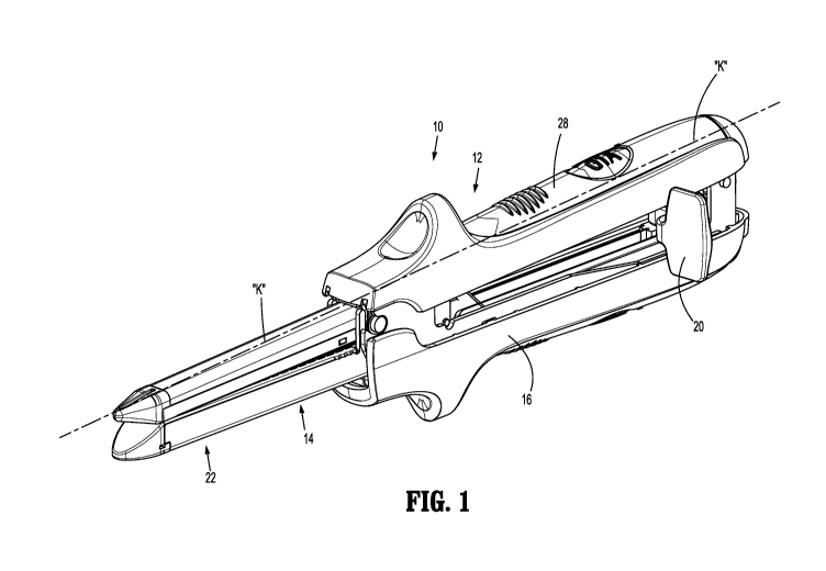
[0011] FIG. 1 is a perspective view of an exemplary embodiment of a
surgical stapling instrument incorporating the lockout member and the firing
member of the present disclosure;
[0012] FIG. 2 is an exploded perspective view of the surgical stapling
instrument illustrating the cartridge body, the anvil body, the staple
cartridge,
the firing member and the lockout member;
[0013] FIG. 3 is an enlarged view of the area of detail identified in FIG.
2 illustrating the lockout member;
[0014] FIGS. 4-5 are first and second perspective views of the lockout
member;
[0015] FIG. 6 is a rear axial view illustrating the lockout member and
the firing member extending through the lockout member;
[0016] FIG. 7 is a perspective view of the cartridge body and the staple
cartridge prior to mounting of the staple cartridge to the cartridge body and
with the firing member in an initial proximal position;
[0017] FIG. 8 is an enlarged view of the area of detail identified in FIG.
7 illustrating the lockout member in the locked position engaging the firing
member;
[0018] FIG. 9 is a cross-sectional view taken along the lines 9-9 of FIG.
7;
4
CA 03090020 2020-07-30
WO 2019/165640 PCT/CN2018/077890
[0019] FIG. 10 is a cross-sectional view taken along the lines 10-10 of
FIG. 7;
[0020] FIG. 11 is a perspective view of the cartridge body with the
staple cartridge mounted to the cartridge body;
[0021] FIG. 12 is a perspective view in partial cross-sectional taken
along the lines 12-12 of FIG. 11 illustrating the lockout member in the
release position;
[0022] FIG. 13 is a cross-sectional view taken along the lines 13-13 of
FIG. 11; and
[0023] FIG. 14 is a perspective view illustrating the firing member in the
actuated distal position.
DETAILED DESCRIPTION OF EMBODIMENTS
[0024] The surgical stapling instrument of the present disclosure will
now be described in detail with reference to the drawings in which like
reference numerals designate identical or corresponding elements in each of
the several views. In this description, the term "proximal" is used generally
to refer to that portion of the device that is closer to a clinician, while
the
term "distal" is used generally to refer to that portion of the device that is
farther from the clinician. In addition, the term clinician is used generally
to
refer to medical personnel including doctors, nurses, and support personnel.
[0025] The surgical stapling instrument of the present disclosure
includes an anvil body, a cartridge body, an actuator or lever that is
configured to move the anvil body and the staple cartridge between a spaced
position and a clamped position, and a firing member. A staple cartridge,
such as a single use loading unit (SULU) or multi-use loading unit
("MULU"), is mountable to the cartridge body. The stapling instrument
further includes a lockout member which prevents actuation of the firing
CA 03090020 2020-07-30
WO 2019/165640 PCT/CN2018/077890
member until the staple cartridge is properly installed on the cartridge body.
The firing member includes structural features which increase the
compressive strength of the firing member thereby enabling firing of multiple
rows of staples, e.g.., two sets of three rows of staples, from the staple
cartridge with relative ease and without deformation of any segment of the
firing member. The firing member defines a reduced profile, particularly
compared to conventional stapling instruments which incorporate a double
channel or U-shaped drive to deploy staples.
[0026] FIGS. 1-2 illustrate an exemplary embodiment of a surgical
stapling instrument incorporating the lockout member and the firing member
of the present disclosure, and designated generally as stapling instrument 10.
The stapling instrument 10 includes an anvil body 12 defining a longitudinal
axis "k", a cartridge body 14 supporting a clamping lever 16, a staple
cartridge or single use loading unit ("SULU") 18 mountable to the cartridge
body 14 and a firing assembly 20. The cartridge body 14 includes a cartridge
support column 22 having a proximal segment 24 and a distal segment 26.
The proximal segment 24 of the cartridge support column 22 receives the
firing assembly 20 and pivotally supports the clamping lever 16. The distal
segment 26 of the cartridge support column 22 receives the staple cartridge
18. The anvil body 12 includes an anvil hand grip 28 and an anvil plate 30.
The clamping lever 16 is pivotally supported on the cartridge body 14 and is
engageable with the anvil body 12 such that movement of the clamping lever
16 from an unclamped position (FIG. 2) to a clamped position (FIG. 1)
moves the anvil body 12 into close approximation with the cartridge body 14.
The firing assembly 20 includes a firing lever 32 and a firing member 34
extending from the firing lever 32. In general, with the clamping lever 16 in
the clamped position with tissue to be joined between the staple cartridge 18
6
CA 03090020 2020-07-30
WO 2019/165640 PCT/CN2018/077890
and the anvil plate 30, the firing assembly 20 is actuated by advancing
movement along the longitudinal axis "k" whereby the firing member 34
cooperates with staple pushers (not shown) within the staple cartridge 18 to
eject a plurality of rows of staples from the staple cartridge 18 for
engagement and deformation by the anvil plate 30. In embodiments, the
staple cartridge 18 accommodates two sets of three rows of staples that are
delivered through tissue. A knife (not shown) may traverse the staple
cartridge 18 to sever tissue between the two sets of rows of staples.
[0027] For a detailed discussion of the construction and operation of an
exemplary surgical stapling instrument, reference may be made to commonly
assigned U.S. Patent U.S. Patent No. 8,505,801 to Ehrenfels et al., the entire
contents of which are incorporated herein by reference.
[0028] Referring now to FIGS. 3-6, the stapling instrument 10 includes a
lockout member 36 which is mounted relative to the firing member 34. The
lockout member 36 is supported by the cartridge body 14 and is movable
between a locked position engaging the firing member 34 and a release
position releasing the firing member 34. The lockout member 36 includes a
lockout base 38 defining a single longitudinal slot 40 for at least partial
reception of the firing member 34. The single longitudinal slot 40 of the
lockout member 36 includes a first lower slot portion 40a and a second upper
slot portion 40b. As best depicted in FIG. 4, the first slot portion 40a
defines
a first dimension "dl" orthogonal to the longitudinal axis "k" and the second
slot portion 40b defines a second dimension "d2" orthogonal to the
longitudinal axis "k". The first dimension "dl" is greater than the second
dimension "d2".
[0029] The lockout member 36 includes a lockout shelf 42 (FIG. 5)
depending from the front or distal end of the lockout base 38. The lockout
7
CA 03090020 2020-07-30
WO 2019/165640 PCT/CN2018/077890
shelf 42 defines a triangular shape in cross-section and is configured to
engage corresponding structure of the firing member 34 to prevent
advancement, i.e., distal longitudinal movement, of the firing assembly 20
when the lockout member 36 is in the locked position. The lockout member
36 further includes a stop 44 extending from the lockout shelf 42 in the
proximal direction. The stop 44 is configured to engage corresponding
structure of the firing member 34 to prevent proximal movement of the firing
member 34, e.g., prior to use of the instrument 10. The stop 44 may extend
within the longitudinal slot 40 of the lockout base 38.
[0030] The lockout member 36 further includes a pair of release legs 46
depending from the rear or proximal end of the lockout base 38. The release
legs 46 are engaged by the staple cartridge 18 when the staple cartridge 18 is
installed relative to the cartridge body 14 to move the lockout member 36
from the locked position to the release position. The release legs 46 may
include arcuate raised segments 48 to enhance engagement with the staple
cartridge 18.
[0031] The lockout member 36 includes a pair of pivot bosses 50
depending radially outwardly from the lockout base 38. The pivot bosses 50
are received within corresponding openings 52 (one is shown in FIG. 7) in
the opposed walls 14a, 14b of the cartridge body 14 to pivotally mount the
lockout member 36 to the cartridge body 14. The pivot bosses 50 may define
chamfered surfaces 54 to facilitate positioning within the openings 52 of the
cartridge body 14. The lockout member 36 is capable of pivotal movement
between the locked position and the release position via the pivot bosses 50.
As best depicted in FIG. 6, a torsion spring 56 is mounted about one of the
pivot bosses 50 and is at least partially disposed within a recess 58 in the
sidewall of the lockout base 38. The torsion spring 56 engages, at one end,
8
CA 03090020 2020-07-30
WO 2019/165640 PCT/CN2018/077890
the rear surface of the recess 58 of the lockout base 38 (FIG. 6) and, at its
other end, the cartridge body 14. The torsion spring 56 normally biases the
lockout member 36 toward its locked position depicted in FIGS. 7-8.
[0032] With reference to FIGS. 3 and 6, the firing member 34 will be
discussed. The firing member 34 defines a plate-like profile having a lower
arcuate segment 60 and a single plate segment 62 extending from the arcuate
segment 60. In embodiments, the firing member 34 is manufactured from a
single plate of steel or the like which is rolled along one longitudinal end
to
define the double layered arcuate segment 60. The arcuate segment 60
substantially increases the compressive strength of the firing member 34,
which may be required to achieve the forces needed to deliver staples of a
staple cartridge 18 having multiple rows of staples, e.g., two sets of three
rows of staples. The arcuate segment 60 resides within the first slot portion
40a of the longitudinal slot 40 of the lockout base 38 and the plate segment
62 resides in the second slot portion 40b of the longitudinal slot 40. The
firing member 34 traverses the longitudinal slot 40 of the lockout base 38
during activation of the firing assembly 20.
[0033] Referring now to FIGS. 7-10, further details of the lockout
member 36 and the firing member 34 will be discussed. In FIGS. 7-10, the
lockout member 36 is in the locked position securing the firing member 34 in
an initial proximal position thereof via the biasing effect of the torsion
spring
56. The staple cartridge 18 is not installed or mounted with respect to the
cartridge body 14. In the locked position, the lockout shelf 42 of the lockout
member 36 is disposed within a correspondingly dimensioned lockout recess
64 (FIGS. 9 and 10) of the firing member 34. The lockout recess 64 may be
polygonal in shape although other configurations are also envisioned. In
embodiments, the lockout recess 64 is defined in part by a distal oblique
9
CA 03090020 2020-07-30
WO 2019/165640 PCT/CN2018/077890
surface 66 (FIG. 10) with which the lockout shelf 42 engages to retain the
lockout member 36 in the locked position and the firing member 34 in the
initial proximal position. The lockout recess 64 is also defined in part by a
proximal stop surface 68 which is engaged by the stop 44 of the lockout
member 36 in the event the firing member 34 is pulled in a proximal
direction, e.g., prior to use of the stapling instrument, to prevent
displacement
of the firing member 34.
[0034] FIGS. 11-13 illustrate the staple cartridge 18 mounted to the
cartridge body 14, and its corresponding effect on the lockout member 36.
Upon mounting of the staple cartridge 18 to the distal segment 26 of the
cartridge body 14, the release legs 46 including the arcuate raised segments
48 are engaged by the staple cartridge 18 and move in a downward direction
toward the cartridge body 14 (FIG. 12). This causes the lockout member 36
to pivot about the pivot bosses 50 in a counterclockwise direction (relative
to
FIGS. 12-13) against the bias of the torsion spring 56 and within the
cartridge
body 14, thereby lifting and releasing the lockout shelf 42 from the lockout
recess 64 of the firing member 34. With the lockout shelf 42 in the release
position, the firing member 34 may be longitudinally advanced toward the
actuated distal position as depicted in FIG. 14 to drive the staples (not
shown)
from the staple cartridge 18.
[0035] Thus, the lockout member 36 and associated firing member 34
cooperate to ensure the staple cartridge 18 is properly installed before the
firing member 34 may be activated. The firing member 34 defines a reduced
plate-like profile configured to traverse the single longitudinal slot 40 of
the
lockout member 36, and is capable of delivering forces sufficient to deploy
multiple rows of staples. The reduced profile of the firing member
potentially creates additional space for the other operating components of the
CA 03090020 2020-07-30
WO 2019/165640 PCT/CN2018/077890
stapling instrument.
[0036] Although the presently disclosed surgical stapling instrument 10
is illustrated as an open-type linear surgical stapler, it is envisioned that
the
benefits of the present disclosure may be incorporated into a variety of
different types of surgical stapling instruments including, e.g., endoscopic
linear staplers.
[0037] Persons skilled in the art will understand that the devices and
methods specifically described herein and illustrated in the accompanying
drawings are non-limiting exemplary embodiments. It is envisioned that the
elements and features illustrated or described in connection with one
exemplary embodiment may be combined with the elements and features of
another without departing from the scope of the present disclosure. As well,
one skilled in the art will appreciate further features and advantages of the
disclosure based on the above-described embodiments. Accordingly, the
disclosure is not to be limited by what has been particularly shown and
described, except as indicated by the appended claims.
11