Note: Descriptions are shown in the official language in which they were submitted.
CA 03090292 2020-07-31
WO 2019/164845 PCT/US2019/018599
INHIBITED EMULSIONS FOR USE IN BLASTING IN REACTIVE GROUND OR UNDER
HIGH TEMPERATURE CONDITIONS
RELATED APPLICATIONS
[0001] This application claims priority to United States Provisional
Application No.
62/632,818 filed February 20, 2018, and titled "INHIBITED EMULSIONS FOR USE IN
BLASTING IN REACTIVE GROUND OR UNDER HIGH TEMPERATURE CONDITIONS," and
U.S. Provisional Application No. 62/773,766 filed November 30, 2018, and
titled "INHIBITED
EMULSIONS FOR USE IN BLASTING IN REACTIVE GROUND OR UNDER HIGH
TEMPERATURE CONDITIONS," which are both hereby incorporated by reference in
their
entireties.
TECHNICAL FIELD
[0002] The present disclosure relates generally to explosives. More
specifically, the
present disclosure relates to methods for delivering inhibited emulsions and
systems related
thereto. In some embodiments, the methods relate to methods of using an
inhibited emulsion
to blast in reactive ground and/or under high temperature conditions.
BRIEF DESCRIPTION OF THE DRAWINGS
[0003] The embodiments disclosed herein will become more fully apparent
from the
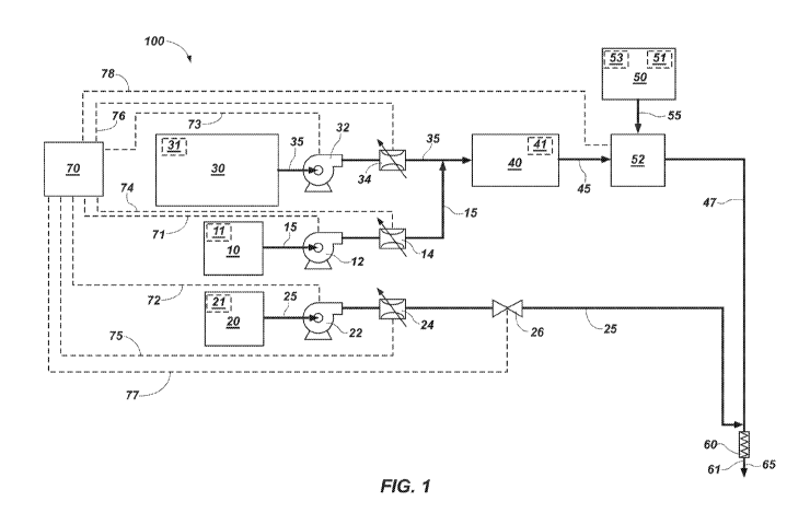
following description and appended claims, taken in conjunction with the
accompanying
drawings. The drawings depict primarily generalized embodiments, which
embodiments will
be described with additional specificity and detail in connection with the
drawings in which:
[0004] FIG. 1 is a process flow diagram of one embodiment of a system for
delivering
explosives.
[0005] FIG. 2 is a flow chart of one embodiment of a method of delivering
an inhibited
emulsion to a blasthole.
[0006] FIG. 3 is a flow chart of one embodiment of blasting in reactive
ground.
DETAILED DESCRIPTION
[0007] Explosive compositions for use in reactive ground and/or under high
temperature
conditions are disclosed herein, along with related methods. Explosives are
commonly used in
the mining, quarrying, and excavation industries for breaking rocks and ore.
Generally, a hole,
referred to as a "blasthole," is drilled into a surface, such as the ground.
An explosive
composition may then be placed in the blasthole. Subsequently, the explosive
composition
may be detonated.
[0008] In some embodiments, the explosive composition is an emulsion or
blend including
the emulsion. In some embodiments, the emulsion includes fuel oil as the
continuous phase
and an oxidizer as the discontinuous phase. For example, in some embodiments,
the
1
CA 03090292 2020-07-31
WO 2019/164845 PCT/US2019/018599
emulsion includes droplets of an aqueous oxidizer solution that are dispersed
in a continuous
phase of fuel oil (i.e., a water-in-oil emulsion).
[0009] "Emulsion" as used herein encompasses both unsensitized emulsion
matrix and
emulsion that has been sensitized into emulsion explosive. For example, the
unsensitized
emulsion matrix may be transportable as a UN Class 5.1 oxidizer. Emulsion
explosives
include a sufficient amount of sensitizing agent to render the emulsion
detonable with
standard detonators. The emulsion may be sensitized at the blast site or even
in the blasthole.
In some embodiments, the sensitizing agent is a chemical gassing agent. In
some
embodiments, the sensitizing agent includes hollow microspheres or other solid
gas-
entraining agents. In some embodiments, the sensitizing agent is gas bubbles
that have been
mechanically introduced into the emulsion. The introduction of gas bubbles
into the emulsion
may decrease the density of the emulsion that is delivered to the blasthole.
[0010] A potential hazard associated with explosive compositions, such as
emulsion
explosives, is premature detonation. Generally, explosive material is left in
a blasthole for a
period of time (i.e., the "sleep time") until it is fired. Stated differently,
the sleep time of an
explosive material is the time between loading of the material into the
blasthole and intentional
firing of the explosive material. Premature detonation (i.e., detonation
during the intended
sleep time) creates significant risks.
[0011] One potential cause of premature detonation is placement of the
explosive
composition in reactive ground. "Reactive ground" is ground that undergoes a
spontaneous
exothermic reaction when it comes in contact with nitrates, such as ammonium
nitrate. Often
the reaction involves the chemical oxidation of sulfides (e.g., iron sulfide
or copper sulfide) by
nitrates and the liberation of heat. In other words, when an explosive
composition is placed in
reactive ground, the sulfides within the reactive ground may react with
nitrates in the explosive
composition. The reaction of nitrates with sulfide-containing ground may
result in an auto-
catalyzed process that can, after some induction time, lead to runaway
exothermic
decomposition. In some instances, the resulting increase in temperature (i.e.,
the resulting
exotherm) can lead to premature detonation. One example of reactive ground is
ground that
includes pyrite.
[0012] A second potential cause of premature detonation is an elevated
ground
temperature. An elevated ground temperature may reduce (or supply) the
activation energy
needed to trigger detonation of an explosive. As used herein the term "high
temperature
ground" refers to ground at a temperature of 55 C or higher.
[0013] Additionally, ground to be blasted can be both high temperature
ground and
reactive ground.
[0014] Several strategies can be employed to prevent an exotherm and
premature
detonation. For example, as discussed in further detail below, the explosive
composition may
2
CA 03090292 2020-07-31
WO 2019/164845 PCT/US2019/018599
include an additive that functions as an inhibitor, such as urea, amines,
basic solutions (e.g.,
aqueous soda ash), sodium nitrate, hydrotalcite, and zinc oxide.
[0015] The inhibitor may reduce thermal degradation of the emulsion
explosive when the
emulsion explosive is in contact with reactive ground and/or ground at an
elevated
temperature. For example, when the emulsion explosive is in contact with
sulfide-containing
ground, the inhibitor may reduce the reaction rate between the nitrate salts
of the
discontinuous oxidizer phase and the sulfides in the reactive ground. It
should be understood
that the inhibited emulsions disclosed herein may not completely prevent an
exotherm and the
resulting premature detonation; however, the inhibited emulsions disclosed
herein may delay
or minimize exotherms and thereby increase the safety of the explosives and
increase the
safe sleep time for the explosives.
[0016] Methods of using the explosive compositions described herein are
also disclosed.
For example, an emulsion explosive described herein can be used to blast in
reactive ground
and/or ground at an elevated temperature. For instance, one method of blasting
in reactive
ground includes the step of placing the emulsion explosive in reactive ground.
For instance,
the emulsion explosive may be loaded into a blasthole drilled within reactive
ground.
[0017] The reactive ground may include any minerals that typically react
with one or more
nitrate salts to produce an exothermic reaction. For instance, in some
embodiments, the
reactive ground includes one or more sulfides. More particularly, some
reactive ground
includes an iron sulfide, such as iron pyrite. Ground can be identified as
reactive ground by
performing the isothermal reactive ground test of the Australian Explosives
Industry and
Safety Group Inc. (see Australian Explosives Industry and Safety Group Inc.,
Code of
Practice: Elevated Temperature and Reaction Ground, March 2017).
[0018] Any methods disclosed herein include one or more steps or actions
for performing
the described method. The method steps and/or actions may be interchanged with
one
another. In other words, unless a specific order of steps or actions is
required for proper
operation of the embodiment, the order and/or use of specific steps and/or
actions may be
modified. Moreover, sub-routines or only a portion of a method described
herein may be a
separate method within the scope of this disclosure. Stated otherwise, some
methods may
include only a portion of the steps described in a more detailed method.
[0019] Reference throughout this specification to "an embodiment" or "the
embodiment"
means that a particular feature, structure, or characteristic described in
connection with that
embodiment is included in at least one embodiment. Thus, the quoted phrases,
or variations
thereof, as recited throughout this specification are not necessarily all
referring to the same
embodiment.
[0020] The phrases "operably connected to," "connected to," and "coupled
to" refer to any
form of interaction between two or more entities, including mechanical,
electrical, magnetic,
3
CA 03090292 2020-07-31
WO 2019/164845 PCT/US2019/018599
electromagnetic, fluid, and thermal interaction. Likewise, "fluidically
connected to" refers to
any form of fluidic interaction between two or more entities. Two entities may
interact with
each other even though they are not in direct contact with each other. For
example, two
entities may interact with each other through an intermediate entity.
[0021] The term "proximal" is used herein to refer to "near" or "at" the
object disclosed.
For example, "proximal the outlet of the delivery conduit" refers to near or
at an outlet of the
delivery conduit.
[0022] As the following claims reflect, inventive aspects lie in a
combination of fewer than
all features of any single foregoing disclosed embodiment. Thus, the claims
following this
Detailed Description are hereby expressly incorporated into this Detailed
Description, with
each claim standing on its own as a separate embodiment. This disclosure
includes all
permutations of the independent claims with their dependent claims.
[0023] Recitation in the claims of the term "first" with respect to a
feature or element does
not necessarily imply the existence of a second or additional such feature or
element. It will be
apparent to those having skill in the art that changes may be made to the
details of the above-
described embodiments without departing from the underlying principles of the
present
disclosure.
[0024] The methods provided herein may allow or permit an explosives
manufacturer to
manufacture a single emulsion for use in both reactive ground and non-reactive
ground
applications. If the emulsion is to be used in a reactive ground application,
a user may add an
inhibitor solution (i.e., a solution including water, an inhibitor, and a
crystallization point
modifier) to the emulsion matrix after manufacture of the emulsion matrix. For
example, the
user may add the inhibitor solution to the emulsion during delivery to the
blasthole.
Accordingly, the sleep time in reactive ground of an emulsion explosive
prepared as disclosed
herein may be longer than the sleep time in reactive ground of an emulsion
explosive lacking
an inhibitor and a crystallization point modifier.
[0025] As stated above, the blasthole may be disposed in reactive ground
and the
emulsion may be an emulsion configured or used for non-reactive ground. A
benefit of the
methods provided herein may be that the emulsion can be tailored to the level
of reactivity of
the reactive ground to be blasted, as there generally tends to be a wide
variety of reactive
ground. For example, the method may include determining ground properties
along the length
or depth of the blasthole. In some embodiments, detailed information about the
blasthole,
including a geologic profile, may be determined. In certain embodiments, a
geologic profile
may be generated based on one or more types of geologic data. Non-limiting
examples of
geologic data include mineralogy (elemental and/or mineral) and temperature.
The geologic
data may be determined directly or indirectly from sources such as seismic
data (such as
received from one or more geophones or other seismic sensors), drilling data,
drill cuttings,
4
CA 03090292 2020-07-31
WO 2019/164845 PCT/US2019/018599
core samples, sensors (e.g., temperature sensors or chemical sensors coupled
to the drill), or
combinations thereof. For example, drill cuttings and/or core samples may be
analyzed using
x-ray or gamma-ray fluorescence, scanning electron microscopy, and other
spectroscopy
and/or microscopy techniques. The geologic data may include information on an
incremental
basis, such as on a per foot basis. Knowledge of the geologic profile or the
ground properties
may be used by one skilled in the art to select an inhibited emulsion tailored
to characteristics
of the ground containing the blasthole to achieve optimum performance of the
explosive.
[0026] Systems for delivering explosives and methods related thereto are
disclosed
herein. It will be readily understood that the components of the embodiments
as generally
described below and illustrated in the Figures herein could be arranged and
designed in a
wide variety of different configurations. Thus, the following more detailed
description of
various embodiments, as described below and represented in the Figures, is not
intended to
limit the scope of the disclosure, but is merely representative of various
embodiments. While
the various aspects of the embodiments are presented in drawings, the drawings
are not
necessarily drawn to scale unless specifically indicated.
[0027] FIG. 1 illustrates a process flow diagram of one embodiment of an
explosives
delivery system 100. The explosives delivery system 100 of FIG. 1 includes
various
components and materials as further detailed below. Additionally, any
combination of the
individual components may include an assembly or subassembly for use in
connection with an
explosives delivery system.
[0028] In the embodiments of FIG. 1, the explosives delivery system 100
includes a first
reservoir 10 configured to store a first gassing agent 11, a second reservoir
20 configured to
store a second gassing agent 21, and a third reservoir 30 configured to store
an emulsion
matrix 31. The explosives delivery system 100 further includes a homogenizer
40 configured
to mix the emulsion matrix 31 and the first gassing agent 11 into a
homogenized product 41.
In some other embodiments, the explosives delivery system 100 may not include
the
homogenizer 40. Stated another way, the explosives delivery system 100 may
lack a
homogenizer.
[0029] In some embodiments, the first gassing agent 11 includes a pH
control agent. The
pH control agent may include an acid. Examples of acids include, but are not
limited to,
organic acids such as citric acid, acetic acid, and tartaric acid. Any pH
control agent known in
the art and compatible with the second gassing agent 21 and a gassing
accelerator, if
present, may be used. The pH control agent may be dissolved in an aqueous
solution.
[0030] In some embodiments, the first reservoir 10 is further configured to
store a gassing
accelerator mixed with the first gassing agent 11. The homogenizer 40 may be
configured to
mix the emulsion matrix 31 and the mixture of the gassing accelerator and the
first gassing
agent 11 into the homogenized product 41. Examples of gassing accelerators
include, but are
CA 03090292 2020-07-31
WO 2019/164845 PCT/US2019/018599
not limited to, thiourea, urea, thiocyanate, iodide, cyanate, acetate,
sulfonic acid and its salts,
and combinations thereof. Any gassing accelerator known in the art and
compatible with the
first gassing agent 11 and the second gassing agent 21 may be used. The pH
control agent
and the gassing accelerator may be dissolved in an aqueous solution.
[0031] In some embodiments, the second gassing agent 21 includes a chemical
gassing
agent configured to react in the emulsion matrix 31 and with the gassing
accelerator, if
present. Examples of chemical gassing agents include, but are not limited to,
peroxides such
as hydrogen peroxide, inorganic nitrite salts such as sodium nitrite,
nitrosamines such as
N,N'-dinitrosopentamethylenetetramine, alkali metal borohydrides such as
sodium
borohydride, and bases such as carbonates including sodium carbonate. Any
chemical
gassing agent known in the art and compatible with the emulsion matrix 31 and
the gassing
accelerator, if present, may be used. The chemical gassing agent may be
dissolved in an
aqueous solution.
[0032] In some embodiments, the emulsion matrix 31 includes a continuous
fuel phase
and a discontinuous oxidizer phase. Any emulsion matrix known in the art may
be used, such
as, by way of non-limiting example, TITAN 1000 G (DYNO NOBEL ).
[0033] Examples of the fuel phase include, but are not limited to, liquid
fuels such as fuel
oil, diesel oil, distillate, furnace oil, kerosene, gasoline, and naphtha;
waxes such as
microcrystalline wax, paraffin wax, and slack wax; oils such as paraffin oils,
benzene, toluene,
and xylene oils, asphaltic materials, polymeric oils such as the low molecular
weight polymers
of olefins, animal oils, such as fish oils, and other mineral, hydrocarbon or
fatty oils; and
mixtures thereof. Any fuel phase known in the art and compatible with the
oxidizer phase and
an emulsifier, if present, may be used.
[0034] The emulsion matrix may provide at least about 95%, at least about
96%, or at
least about 97% of the oxygen content of the sensitized product.
[0035] Examples of the oxidizer phase include, but are not limited to,
oxygen-releasing
salts. Examples of oxygen-releasing salts include, but are not limited to,
alkali and alkaline
earth metal nitrates, alkali and alkaline earth metal chlorates, alkali and
alkaline earth metal
perchlorates, ammonium nitrate, ammonium chlorate, ammonium perchlorate, and
mixtures
thereof, such as a mixture of ammonium nitrate and sodium or calcium nitrates.
Any oxidizer
phase known in the art and compatible with the fuel phase and an emulsifier,
if present, may
be used. The oxidizer phase may be dissolved in an aqueous solution, resulting
in an
emulsion matrix known in the art as a "water-in-oil" emulsion. The oxidizer
phase may not be
dissolved in an aqueous solution, resulting in an emulsion matrix known in the
art as a "melt-
in-oil" emulsion.
[0036] In some embodiments, the emulsion matrix 31 further includes an
emulsifier.
Examples of emulsifiers include, but are not limited to, emulsifiers based on
the reaction
6
CA 03090292 2020-07-31
WO 2019/164845 PCT/US2019/018599
products of poly[alk(en)yl] succinic anhydrides and alkylamines, including the
polyisobutylene
succinic anhydride (PiBSA) derivatives of alkanolamines. Additional examples
of emulsifiers
include, but are not limited to, alcohol alkoxylates, phenol alkoxylates,
poly(oxyalkylene)glycols, poly(oxyalkylene) fatty acid esters, amine
alkoxylates, fatty acid
esters of sorbitol and glycerol, fatty acid salts, sorbitan esters,
poly(oxyalkylene) sorbitan
esters, fatty amine alkoxylates, poly(oxyalkylene) glycol esters, fatty acid
amines, fatty acid
amide alkoxylates, fatty amines, quaternary amines, alkyloxazolines,
alkenyloxazolines,
imidazolines, alkylsulphonates, alkylsulphosuccinates, alkylarylsulphonates,
alkylphosphates,
alkenylphosphates, phosphate esters, lecithin, copolymers of
poly(oxyalkylene)glycol and
poly(12-hydroxystearic) acid, 2-alkyl and 2-alkeny1-4,4'-
bis(hydroxymethyl)oxazoline, sorbitan
mono-oleate, sorbitan sesquioleate, 2-oley1-4,4'bis(hydroxymethyl)oxazoline,
and mixtures
thereof. Any emulsifier known in the art and compatible with the fuel phase
and the oxidizer
phase may be used.
[0037] The explosives delivery system 100 further includes a first pump 12
configured to
pump the first gassing agent 11. The inlet of the first pump 12 is fluidically
connected to the
first reservoir 10. The outlet of the first pump 12 is fluidically connected
to the first flowmeter
14 configured to measure a stream 15 of the first gassing agent 11. The first
flowmeter 14 is
fluidically connected to the homogenizer 40. The stream 15 of the first
gassing agent 11 may
be introduced into a stream 35 of the emulsion matrix 31 upstream from the
homogenizer 40,
including before or after, a third pump 32 or, before or after, a third
flowmeter 34. The stream
15 may be introduced along the centerline of the stream 35. FIG. 1 illustrates
the flow of the
stream 15 of the first gassing agent 11 from the first reservoir 10, through
the first pump 12
and the first flowmeter 14, and into the homogenizer 40.
[0038] The explosives delivery system 100 further includes a second pump 22
configured
to pump the second gassing agent 21. The inlet of the second pump 22 is
operably connected
to the second reservoir 20. The outlet of the second pump 22 is fluidically
connected to a
second flowmeter 24 configured to measure the flow of a stream 25 of the
second gassing
agent 21. The second flowmeter 24 is fluidically connected to a valve 26. The
valve 26 is
configured to control the stream 25 of the second gassing agent 21. The valve
26 is fluidically
connected to a delivery conduit (not shown) proximal of the outlet of the
delivery conduit and
proximal of the inlet of a mixer 60. The valve 26 may include a control valve.
Examples of
control valves include, but are not limited to, angle seat valves, globe
valves, butterfly valves,
and diaphragm valves. Any valve known in the art and compatible with
controlling the flow of
the second gassing agent 21 may be used. FIG. 1 illustrates the flow of the
stream 25 of the
second gassing agent 21 from the second reservoir 20, through the second pump
22, the
second flowmeter 24, and the valve 26, and into stream a 47.
7
CA 03090292 2020-07-31
WO 2019/164845 PCT/US2019/018599
[0039] The explosives delivery system 100 further includes the third pump
32 configured
to pump the emulsion matrix 31. The inlet of the third pump 32 is fluidically
connected to the
third reservoir 30. The outlet of the third pump 32 is fluidically connected
to the third flowmeter
34 configured to measure the stream 35 of the emulsion matrix 31. The third
flowmeter 34 is
fluidically connected to the homogenizer 40. FIG. 1 illustrates the flow of
the stream 35 of the
emulsion matrix 31 from the third reservoir 30, through the third pump 32 and
the third
flowmeter 34, and into the homogenizer 40.
[0040] In some embodiments, the explosives delivery system 100 is
configured to convey
the second gassing agent 21 at a mass flow rate of less than about 5%, less
than about 4%,
less than about 2%, or less than about 1% of a mass flow rate of the emulsion
matrix 31.
[0041] The homogenizer 40 may be configured to homogenize the emulsion
matrix 31
when forming the homogenized product 41. As used herein, "homogenize" or
"homogenizing"
refers to reducing the size of oxidizer phase droplets in the fuel phase of an
emulsion matrix,
such as the emulsion matrix 31. Homogenizing the emulsion matrix 31 increases
the viscosity
of the homogenized product 41 as compared to the emulsion matrix 31. The
homogenizer 40
may also be configured to mix the stream 35 of the emulsion matrix 31 and the
stream 15 of
the first gassing agent 11 into the homogenized product 41. The stream 45 of
the
homogenized product 41 exits the homogenizer 40. Pressure from the stream 35
and the
stream 15 may supply the pressure for flowing the stream 45.
[0042] The homogenizer 40 may reduce the size of oxidizer phase droplets by
introducing
a shearing stress on the emulsion matrix 31 and the first gassing agent 11.
The homogenizer
40 may include a valve configured to introduce a shearing stress on the
emulsion matrix 31
and the first gassing agent 11. The homogenizer 40 may further include mixing
elements,
such as, by way of non-limiting example, static mixers and/or dynamic mixers,
such as
augers, for mixing the stream 15 of the first gassing agent 11 with the stream
35 of the
emulsion matrix 31.
[0043] Homogenizing the emulsion matrix 31 when forming the homogenized
product 41
may be beneficial for the sensitized product 61. For example, the reduced
oxidizer phase
droplet size and increased viscosity of the sensitized product 61, as compared
to an
unhomogenized sensitized product, may mitigate gas bubble coalescence of the
gas bubbles
generated by introduction of second gassing agent 21. Likewise, the effects of
static head
pressure on gas bubble density in a homogenized sensitized product 61 are
reduced as
compared to an unhomogenized sensitized product. Therefore, gas bubble
migration is less in
the homogenized sensitized product 61 as compared to an unhomogenized
sensitized
product. As a result, the as-loaded density of the homogenized sensitized
product 61 at a
particular depth of a blasthole is closer to the conveyed density of the
homogenized sensitized
product 61 at that depth than would be the case for the as-loaded density of
an
8
CA 03090292 2020-07-31
WO 2019/164845 PCT/US2019/018599
unhomogenized sensitized product conveyed instead. The increased viscosity of
the
homogenized sensitized product 61 also tends to reduce migration of the
product into cracks
and voids in the surrounding material of a blasthole, as compared to an
unhomogenized
sensitized product.
[0044] In some embodiments, the homogenizer 40 does not substantially
homogenize the
emulsion matrix 31. In such embodiments, the homogenizer 40 includes elements
primarily
configured to mix the stream 35 and the stream 15, but does not include
elements primarily
configured to reduce the size of oxidizer phase droplets in the emulsion
matrix 31. In such
embodiments, the sensitized product 61 would be an unhomogenized sensitized
product.
"Primarily configured" as used herein refers to the main function that an
element was
configured to perform. For example, any mixing element(s) of the homogenizer
40 may have
some effect on oxidizer phase droplet size, but the main function of the
mixing elements may
be to mix the stream 15 and the stream 35.
[0045] The explosives delivery system 100 further includes a fourth
reservoir 50
configured to store a lubricant 51 and/or an inhibitor solution 53 (discussed
in further detail
below) and a lubricant injector 52 configured to lubricate conveyance of the
homogenized
product 41 through the inside of the delivery conduit. The fourth reservoir 50
is fluidically
connected to the lubricant injector 52. The lubricant injector 52 may be
configured to inject an
annulus of the lubricant 51 and/or the inhibitor solution 53 that surrounds
the stream 45 of the
homogenized product 41 and lubricates flow of the homogenized product 41
inside the
delivery conduit. The lubricant 51 may include water. The inhibitor solution
53 may include
water, an inhibitor, and a crystallization point modifier. The homogenizer 40
is fluidically
connected to the lubricant injector 52. The lubricant injector 52 is operably
connected to the
delivery conduit. The stream 45 of the homogenized product 41 enters the
lubricant injector
52. The stream 55 of the lubricant 51 and/or the inhibitor solution 53 exits
the fourth reservoir
50 and is introduced by the lubricant injector 52 to the stream 45. The stream
55 may be
injected as an annulus that substantially radially surrounds the stream 45.
The stream 47 exits
the lubricant injector 52 and includes the stream 45 substantially radially
surrounded by the
stream 55. The stream 55 of the lubricant 51 and/or the inhibitor solution 53
can lubricate the
flow of the stream 45 through the delivery conduit.
[0046] In some embodiments, the annulus of the lubricant 51 and/or the
inhibitor solution
53 that surrounds the stream 45 of the homogenized product 41 may comprise
from about 1
weight percent (wt%) to about 14 wt% of the total product (the lubricant 51
and/or inhibitor
solution 53 plus the homogenized product 41 and any sensitizing agent) in the
blasthole. In
some other embodiments, the annulus of the lubricant 51 and/or the inhibitor
solution 53 that
surrounds the stream 45 of the homogenized product 41 may comprise from about
2 wt% to
9
CA 03090292 2020-07-31
WO 2019/164845 PCT/US2019/018599
about 12 wt%, from about 6 wt% to about 10 wt%, or about 8 wt% of the total
product in the
blasthole.
[0047] The explosives delivery system 100 further includes a delivery
conduit. The
delivery conduit is operably connected to the lubricant injector. The delivery
conduit is
configured to convey the stream 47 to the mixer 60. The delivery conduit is
configured for
insertion into a blasthole.
[0048] The explosives delivery system 100 further includes the mixer 60
located proximal
the outlet of the delivery conduit. The mixer 60 is configured to mix the
homogenized product
41 and the lubricant 51 and/or the inhibitor solution 53 in the stream 47 with
the second
gassing agent 21 in the stream 25 to form the sensitized product 61 in the
stream 65. The
mixer may include a static mixer. An example of a static mixer includes, but
is not limited to, a
helical static mixer. Any static mixer known in the art and compatible with
mixing the second
gassing agent 21, the homogenized product 41, and the lubricant 51 and/or the
inhibitor
solution 53 may be used.
[0049] In some embodiments, the stream 15 of the first gassing agent 11 is
not introduced
to the stream 35 upstream from the homogenizer 40. Instead, the stream 15 of
the first
gassing agent 11 may be introduced to the stream 45 of the homogenized product
41 after the
homogenizer 40 or into the stream 47 after the lubricant injector 52. The
stream 15 may be
injected along the centerline of the stream 45 or the stream 47. In these
embodiments, the
first gassing agent 11 of the stream 15 may be mixed with the homogenized
product 41 and
the second gassing agent 25 at the mixer 60.
[0050] The explosives delivery system 100 further includes a control system
70
configured to vary the flow rate of the stream 25 relative to the flow rate of
the stream 47. The
control system 70 may be configured to vary the flow rate of the stream 25
while the
sensitized product 61 is continuously formed and conveyed to the blasthole.
The control
system 70 may be configured to vary the flow rate of the stream 25 while also
varying the flow
rate of the stream 15, the stream 35, and the stream 55 to change the flow
rate of the stream
47.
[0051] The control system 70 may be configured to automatically vary the
flow rate of the
stream 25 as the blasthole is filled with the sensitized product 61, depending
upon a desired
sensitized product density of the sensitized product 61 at a particular depth
of the blasthole.
The control system 70 may be configured to determine the desired sensitized
product density
based upon a desired explosive energy profile within the blasthole. The
control system 70
may be configured to adjust the flow rate of the stream 15 of the first
gassing agent 11 based
on the temperature of the emulsion matrix 31 and the desired reaction rate of
the second
gassing agent 21 in the homogenized product 41. The temperature of the
emulsion matrix 31
may be measured in the third reservoir 30. The control system 70 may be
configured to vary
CA 03090292 2020-07-31
WO 2019/164845 PCT/US2019/018599
the flow rate of the stream 25 to maintain a desired sensitized product
density based, at least
in part, on variations in the flow rate of the stream 35 to the homogenizer
40.
[0052] The control system 70 includes a computer (not shown) including a
processor (not
shown) operably connected to a memory device (not shown). The memory device
stores
programming for accomplishing desired functions of the control system 70 and
the processor
implements the programming. The control system 70 communicates with the first
pump 12 via
a communication system 71. The control system 70 communicates with the second
pump 22
via a communication system 72. The control system 70 communicates with the
third pump 32
via a communication system 73. The control system 70 communicates with the
first flowmeter
14 via a communication system 74. The control system 70 communicates with the
second
flowmeter 24 via a communication system 75. The control system 70 communicates
with the
third flowmeter 34 via a communication system 76. The control system 70
communicates with
the valve 26 via a communication system 77. The control system 70 communicates
with the
lubricant injector 52 via a communication system 78. The communication systems
71, 72, 73,
74, 75, 76, 77, 78 may include one or more wires and/or wireless communication
systems.
[0053] In some embodiments, the explosives delivery system 100 is
configured for
delivering a blend of the sensitized product 61 with solid oxidizers and
additional liquid fuels.
In such embodiments, the delivery conduit may not be inserted into the
blasthole, but instead
the sensitized product 61 may be blended with solid oxidizer and additional
liquid fuel. The
resulting blend may be poured into a blasthole, such as from the discharge of
an auger chute
located over the mouth of a blasthole.
[0054] For example, the explosives delivery system 100 may include a fifth
reservoir
configured to store the solid oxidizer. The explosives delivery system 100 may
further include
a sixth reservoir configured to store an additional liquid fuel, separate from
the liquid fuel that
is part of the emulsion matrix 31. A hopper may operably connect the fifth
reservoir to a
mixing element, such as an auger. The mixing element may be fluidically
connected to the
sixth reservoir. The mixing element may also be fluidically connected to the
outlet of the
delivery conduit configured to form the sensitized product 61. The mixing
element may be
configured to blend the sensitized product 61 with the solid oxidizer of the
fifth reservoir and
the liquid fuel of the sixth reservoir. A chute may be connected to the
discharge of the mixing
element and configured to convey blended sensitized product 61 to a blasthole.
For example,
the sensitized product 61 may be blended in an auger with ammonium nitrate and
No. 2 fuel
oil to form a "heavy ANFO" blend.
[0055] The explosives delivery system 100 may include additional reservoirs
for storing
solid sensitizers and/or energy increasing agents. These additional components
may be
mixed with the solid oxidizer of the fifth reservoir or may be mixed directly
with the
homogenized product 41 or the sensitized product 61. In some embodiments, the
solid
11
CA 03090292 2020-07-31
WO 2019/164845 PCT/US2019/018599
oxidizer, the solid sensitizer, and/or the energy increasing agent may be
blended with the
sensitized product 61 without the addition of any liquid fuel from the sixth
reservoir.
[0056] Examples of solid sensitizers include, but are not limited to, glass
or hydrocarbon
microballoons, cellulosic bulking agents, expanded mineral bulking agents, and
the like.
Examples of energy-increasing agents include, but are not limited to, metal
powders, such as
aluminum powder. Examples of the solid oxidizer include, but are not limited
to, oxygen-
releasing salts formed into porous spheres, also known in the art as "prills."
Examples of
oxygen-releasing salts are those disclosed above regarding the oxidizer phase
of the
emulsion matrix 31. Prills of the oxygen-releasing salts may be used as the
solid oxidizer. Any
solid oxidizer known in the art and compatible with the liquid fuel may be
used. Examples of
the liquid fuel are those disclosed above regarding the fuel phase of the
emulsion matrix 31.
Any liquid fuel known in the art and compatible with the solid oxidizer may be
used.
[0057] It should be understood that the explosives delivery system 100 may
further
include additional components compatible with delivering explosives.
[0058] It should be understood that the explosives delivery system 100 may
be modified
to exclude components. For example, the explosives delivery system 100 may
exclude the
homogenizer 40. For example, the explosives delivery system 100 may be
modified to
exclude components not necessary for flowing the streams 15, 25, 35. For
example, one or
more of the first pump 12, the second pump 22, the third pump 32, the first
flowmeter 14, the
second flowmeter 24, and the third flowmeter 34 may not be present. For
example, instead of
the first pump 12 being present, the explosives delivery system 100 may rely
upon the
pressure head in the first reservoir 10 to supply sufficient pressure for flow
of the stream 15 of
the first gassing agent 11. In another example, the control system 70 may not
be present and
instead manual controls may be present for controlling the flow of the streams
15, 25, 35, 45.
[0059] It should further be understood that FIG. 1 is a process flow
diagram and does not
dictate physical location of any of the components. For example, the third
pump 32 may be
located internally within third reservoir 30.
[0060] Another aspect of the disclosure is related to methods of delivering
an inhibited
emulsion to a blasthole. In some embodiments, the method may include supplying
an
emulsion including a discontinuous oxidizer phase and a continuous fuel phase
on a mobile
processing unit. The method may include supplying a separate inhibitor
solution including
water, an inhibitor, and a crystallization point modifier on the mobile
processing unit. The
method may also include mixing the emulsion with the inhibitor solution on the
mobile
processing unit to form an inhibited emulsion. Furthermore, the method may
include
conveying the inhibited emulsion to a blasthole.
[0061] In certain embodiments the method may include supplying an emulsion
comprising
a discontinuous oxidizer phase and a continuous fuel phase and supplying a
separate
12
CA 03090292 2020-07-31
WO 2019/164845 PCT/US2019/018599
inhibitor solution comprising water, an inhibitor, and a crystallization point
modifier. The
method may include mixing the emulsion with the inhibitor solution to form an
inhibited
emulsion and conveying the inhibited emulsion to a blasthole. Furthermore, the
method may
include determining whether the blasthole is disposed in reactive ground, high
temperature
ground, or both.
[0062] As discussed above, the emulsion and the separate inhibitor solution
may be
supplied on a mobile processing unit. The emulsion may be mixed with the
inhibitor solution
on the mobile processing unit to form the inhibited emulsion. Furthermore, the
inhibited
emulsion may be conveyed to a blasthole from the mobile processing unit.
Supplying the
separate inhibitor solution may include mixing water, the inhibitor, and the
crystallization point
modifier on the mobile processing unit. Supplying the separate inhibitor
solution may include
introducing the inhibitor solution into a reservoir disposed on the mobile
processing unit.
[0063] In certain embodiments, the emulsion and the separate inhibitor
solution may be
supplied in a plant or factory. The emulsion may be mixed with the inhibitor
solution in the
plant to form the inhibited emulsion. The inhibited emulsion may then be
supplied on a mobile
processing unit. Furthermore, the inhibited emulsion may then be conveyed to a
blasthole
from the mobile processing unit.
[0064] Examples of inhibitors include, but are not limited to, urea,
amines, basic solutions
(e.g., aqueous soda ash), sodium nitrate, hydrotalcite, and zinc oxide. Any
inhibitor known in
the art and compatible with the emulsion may be used. In some embodiments, the
wt% of the
inhibitor in the inhibited emulsion may be about 1 wt% to about 10 wt%, about
1.5 wt% to
about 7.5 wt%, about 2 wt% to about 5 wt%, or about 3 wt%.
[0065] A "crystallization point modifier" as used herein refers to an agent
that, when in a
mixture or solution, is configured to reduce the crystallization point of the
mixture or the
solution. For example, a mixture may have a crystallization point of 18 C,
however, when a
crystallization point modifier is added to the mixture, the crystallization
point of the mixture
may decrease to 3 C. In some embodiments, the mixture or solution may include
an inhibitor
(e.g., urea) and the crystallization point modifier may reduce the
crystallization point of the
inhibitor in the mixture or solution such that the mixture or solution does
not clog or inhibit flow
of one or more of the streams (e.g., in a conduit on the mobile processing
unit). Examples of
crystallization point modifiers include, but are not limited to, calcium
nitrate, sodium nitrate,
and calcium chloride. Any crystallization point modifier known in the art and
compatible with
the emulsion may be used. In certain embodiments, the wt% of the
crystallization point
modifier in the inhibited emulsion may be about 0.1 wt% to about 8 wt%, about
0.5 wt% to
about 6 wt%, about 1 wt% to about 5 wt%, or about 2 wt% to about 4 wt%.
[0066] The inhibitor solution can also include ethylene glycol. In various
embodiments, the
wt% of the ethylene glycol in the inhibited emulsion may be about 0.1 wt% to
about 1 wt%,
13
CA 03090292 2020-07-31
WO 2019/164845 PCT/US2019/018599
about 0.2 wt% to about 0.8 wt%, about 0.3 wt% to about 0.7 wt%, or about 0.4
wt% to about
0.6 wt%. As noted above, the inhibitor solution can also include water. In
some embodiments,
the wt% of the water in the inhibited emulsion may be about 0.5 wt% to about
10 wt%, about 1
wt% to about 9 wt%, about 2 wt% to about 7 wt%, or about 3 wt% to about 5 wt%.
Other
suitable weight percentages of the inhibitor, the crystallization point
modifier, water, and/or
ethylene glycol in the inhibited emulsion may also be within the scope of this
disclosure.
[0067] In some embodiments, water, the inhibitor, and the crystallization
point may be
mixed to form the inhibitor solution and then the inhibitor solution may be
introduced into a
reservoir on the mobile processing unit (e.g., such as the fourth reservoir 50
of FIG. 1). Stated
another way, a premixed inhibitor solution may be introduced into a reservoir
on the mobile
processing unit. In some other embodiments, water, the inhibitor, and the
crystallization point
may be mixed to form the inhibitor solution within a reservoir disposed on the
mobile
processing unit.
[0068] In certain embodiments, the emulsion can be supplied including an
inhibitor (e.g.,
urea). The method can include mixing the emulsion having the inhibitor with
the inhibitor
solution such that the concentration of inhibitor in the emulsion is
increased. In certain
embodiments, supplying the emulsion can include supplying an emulsion matrix.
Stated
another way, the emulsion may not be sensitized. The method may further
include introducing
a sensitizing agent (e.g., a chemical gassing agent, hollow microspheres or
other solid gas-
entraining agents, gas bubbles, etc.) to the emulsion matrix to form an
emulsion explosive.
The sensitizing agent may be introduced to the emulsion matrix to form the
emulsion
explosive prior to introduction of the emulsion explosive into a delivery
conduit. The mobile
processing unit can include the delivery conduit. For example, the delivery
conduit may be a
component of the mobile processing unit. In other embodiments, the sensitizing
agent may be
introduced to the emulsion matrix to form the emulsion explosive proximal an
outlet of the
delivery conduit. For example, the sensitizing agent may be introduced to the
emulsion matrix
at or adjacent a nozzle coupled to a distal end of the delivery conduit (such
as described
above the exemplary explosive delivery system 100). In various embodiments,
supplying the
emulsion may include supplying an emulsion explosive.
[0069] In some embodiments, the emulsion (i.e., the emulsion matrix or the
emulsion
explosive) may be mixed with the inhibitor solution to form the inhibited
emulsion prior to
introduction of the inhibited emulsion to the delivery conduit. For example,
the emulsion and
the inhibitor solution can be mixed at a position prior to an inlet of the
delivery conduit. In
some other embodiments, the emulsion and the inhibitor may be introduced to
the delivery
conduit and then the emulsion may be mixed with the inhibitor solution to form
the inhibited
emulsion. The emulsion and the inhibitor may be mixed in the delivery conduit,
for example, at
a position proximal of an outlet of the delivery conduit.
14
CA 03090292 2020-07-31
WO 2019/164845 PCT/US2019/018599
[0070] In certain embodiments, the emulsion may be mixed with the inhibitor
solution to
form the inhibited emulsion prior to introduction of the inhibited emulsion to
the homogenizer.
For example, the emulsion and the inhibitor solution can be mixed at a
position prior to an
inlet of the homogenizer. In certain other embodiments, the emulsion and the
inhibitor may be
introduced to the homogenizer to form a homogenized product.
[0071] The method of delivering the inhibited emulsion to the blasthole may
also include
determining a concentration, a flowrate, or both of the inhibitor solution to
achieve a desired
inhibition of reactive ground by the inhibited emulsion. In some embodiments,
a first portion of
reactive ground may have higher reactivity than a second portion of reactive
ground.
Accordingly, it may be determined that a higher concentration and/or flowrate
of the inhibitor
solution should be used for the first portion of reactive ground than for the
second portion of
reactive ground to inhibit or limit the possibility of premature detonation of
the inhibited
emulsion in the reactive ground. The method of delivering the inhibited
emulsion to the
blasthole may also include varying a concentration, a flowrate, or both of the
inhibitor solution
to achieve a desired inhibition of reactive ground by the inhibited emulsion.
For example,
where a first portion of reactive ground has a higher reactivity than a second
portion of
reactive ground, the concentration and/or flowrate of the inhibitor solution
may be varied (e.g.,
increased) for the first portion of reactive ground in comparison to the
second portion of
reactive ground.
[0072] In certain embodiments, an annulus of the inhibitor solution can be
injected or
introduced into the delivery conduit to lubricate conveyance of the emulsion
along at least a
portion of the delivery conduit. In various embodiments, the inhibitor
solution may be injected
or introduced to a centerline of a stream of the emulsion (e.g., within at
least a portion of the
delivery conduit).
[0073] Conveying the inhibited emulsion to the blasthole may include
inserting the
delivery conduit into the blasthole and/or conveying the inhibited emulsion
into the blasthole
via the delivery conduit.
[0074] Another aspect of the disclosure is related to methods of blasting
in reactive
ground. In certain embodiments, the method may include supplying an emulsion
including a
discontinuous oxidizer phase and a continuous fuel phase on a mobile
processing unit. The
method may include supplying an inhibitor on the mobile processing unit. The
method may
also include mixing the inhibitor solution at a determined concentration,
flowrate, or both with
the emulsion on the mobile processing unit to form an inhibited emulsion with
sufficient
inhibitor to achieve a desired inhibition of particular reactive ground by the
inhibited emulsion.
Furthermore, the method may include conveying the inhibited emulsion to a
blasthole in the
particular reactive ground.
CA 03090292 2020-07-31
WO 2019/164845 PCT/US2019/018599
[0075] In various embodiments, the method of blasting in reactive ground,
high
temperature ground, or both may include supplying an emulsion comprising a
discontinuous
oxidizer phase and a continuous fuel phase and supplying an inhibitor. The
method may
further include mixing the inhibitor at a determined concentration, flowrate,
or both with the
emulsion to form an inhibited emulsion with sufficient inhibitor to achieve a
desired inhibition
of particular reactive ground, high temperature ground, or both, by the
inhibited emulsion. The
method may include conveying the inhibited emulsion to a blasthole in the
particular reactive
ground, high temperature ground, or both. Furthermore, the method may include
determining
whether the ground is reactive ground, high temperature ground, or both.
[0076] As discussed above, the emulsion and the inhibitor may be supplied
on a mobile
processing unit. The inhibitor may be mixed with the emulsion on the mobile
processing unit
to form the inhibited emulsion. Furthermore, the inhibited emulsion may be
conveyed to a
blasthole from the mobile processing unit.
[0077] In some embodiments, the emulsion and the inhibitor may be supplied
in a plant.
The inhibitor may be mixed with the emulsion in the plant to form the
inhibited emulsion. The
inhibited emulsion may be supplied on a mobile processing unit. Furthermore,
the inhibited
emulsion may then be conveyed to a blasthole from the mobile processing unit.
[0078] The inhibitor may be a component or ingredient of an inhibitor
solution. As
discussed above, the inhibitor solution may include water and a
crystallization point modifier in
addition to the inhibitor. Furthermore, the inhibitor solution may also
include ethylene glycol.
[0079] In various embodiments, the method of blasting in reactive ground
may include
determining the concentration, the flowrate, or both of the inhibitor solution
to achieve a
desired inhibition of particular reactive ground by the inhibited emulsion.
The method of
blasting in reactive ground may also include varying the concentration, the
flowrate, or both of
the inhibitor solution to achieve a desired inhibition of particular reactive
ground by the
inhibited emulsion.
[0080] In some embodiments, there may be a plurality of blastholes. Each of
the
blastholes may have a different level of ground reactivity. In certain
embodiments, a first
portion of the blastholes (e.g., a first group of one or more blastholes) may
have a first level of
ground reactivity and a second portion of the blastholes (e.g., a second group
of one or more
blastholes) may have a second level of ground reactivity. There may also be a
third portion, a
fourth portion, and so on of the blastholes. Stated another way, the plurality
of blastholes may
form a pattern wherein each blasthole, or each portion of the blastholes, has
a particular or
unique level of ground reactivity. The method of blasting in reactive ground
may include
determining the concentration, the flowrate, or both of the inhibitor solution
to achieve a
desired inhibition of particular reactive ground by the inhibited emulsion in
each of the
blastholes or in each of the one or more portions of the blastholes. The
method of blasting in
16
CA 03090292 2020-07-31
WO 2019/164845 PCT/US2019/018599
reactive ground may also include varying the concentration, the flowrate, or
both of the
inhibitor solution to achieve a desired inhibition of particular reactive
ground by the inhibited
emulsion in each of the blastholes or in each of the one or more portions of
the blastholes.
[0081] Some methods of blasting in reactive ground involve the step of
letting the inhibited
emulsion sleep for at least one day, at least two days, at least two weeks, at
least one month,
at least two months, or at least three months. For example, the inhibited
emulsion may sleep
for some period of time in reactive ground without provoking a runaway
exothermic reaction
that significantly changes the temperature of the emulsion explosive. The
avoidance of such a
runaway exothermic reaction may prevent or reduce the risk of premature
detonation.
[0082] After the inhibited emulsion has been placed in the reactive ground,
the inhibited
emulsion may be detonated at the desired time. For example, in some
embodiments, the
inhibited emulsion may be detonated after the inhibited emulsion has been
allowed to sleep
for a period of greater than three hours, five hours, 12 hours, 24 hours, two
days, one week,
two weeks, at least one month, at least two months, or at least three months.
[0083] Another aspect of the disclosure is related to an inhibitor
solution. In some
embodiments, the inhibitor solution can include water, an inhibitor, and a
crystallization point
modifier. The inhibitor solution may also include ethylene glycol.
[0084] The wt% of the inhibitor in the inhibitor solution may be about 10
wt% to about 50
wt%, about 20 wt% to about 50 wt%, about 30 wt% to about 50 wt%, or about 40
wt% to
about 50 wt%. The wt% of the crystallization point modifier in the inhibitor
solution may about
wt% to about 35 wt%, about 10 wt% to about 30 wt%, about 12 wt% to about 25
wt%, or
about 14 wt% to about 20 wt%. The wt% of the water in the inhibitor solution
may be about 15
wt% to about 50 wt%, about 20 wt% to about 45 wt%, about 25 wt% to about 42
wt%, or
about 30 wt% to about 40 wt%. The wt% of the ethylene glycol in the inhibitor
solution may be
about 1 wt% to about 10 wt%, about 2 wt% to about 8 wt%, about 4 wt% to about
6 wt%, or
about 5 wt%. Other suitable weight percentages of the inhibitor, the
crystallization point
modifier, water, and/or ethylene glycol in the inhibitor solution may also be
within the scope of
this disclosure.
[0085] Another aspect of the disclosure is related to an explosives
delivery system
(analogous to the explosives delivery system 100 of FIG. 1). The explosives
delivery system
can include an emulsion reservoir (such as the third reservoir 30 of FIG. 1)
configured to store
an emulsion including a discontinuous oxidizer phase and a continuous fuel
phase (such as
the emulsion matrix 31 of FIG. 1). The explosives delivery system can also
include an inhibitor
solution reservoir (such as the fourth reservoir 50 of FIG. 1) configured to
store a separate
inhibitor solution (such as the inhibitor solution 53 of FIG. 1) including
water, an inhibitor, and
a crystallization point modifier. A heater may be operably connected to the
inhibitor solution
reservoir. The heater may be configured to maintain the temperature of the
inhibitor solution
17
CA 03090292 2020-07-31
WO 2019/164845 PCT/US2019/018599
such that the temperature of the inhibitor solution does not drop below the
crystallization point
of the inhibitor solution. For example, in cold weather conditions the heater
may help maintain
the inhibitor solution at a temperature above the crystallization point of the
inhibitor solution.
[0086] In some embodiments, the explosives delivery system can further
include an
inhibitor solution injector operably connected to the emulsion reservoir and
the inhibitor
solution reservoir. The inhibitor solution injector can be configured to
introduce the inhibitor
solution to the emulsion. Furthermore, a delivery conduit may be operably
connected to the
inhibitor solution injector. In certain embodiments, the delivery conduit can
be configured to
convey the emulsion and the inhibitor solution. The delivery conduit may also
be configured
for insertion into a blasthole.
[0087] The explosives delivery system may include a mixer (such as the
mixer 60 of FIG.
1) disposed proximal of an outlet of the delivery conduit. In various
embodiments, the mixer
may be configured to mix the emulsion and the inhibitor solution to form an
inhibited emulsion.
[0088] The inhibitor solution injector may be a lubricant injector (such as
the lubricant
injector 52 of FIG. 1) configured to inject an annulus of the inhibitor
solution to lubricate
conveyance of the emulsion matrix along the delivery conduit. In other
embodiments, the
inhibitor solution injector may be configured to inject the inhibitor solution
to a centerline of a
stream of the emulsion matrix within the delivery conduit.
[0089] FIG. 2 is a flow chart of one embodiment of a method of delivering
an inhibited
emulsion to a blasthole. In this embodiment, the method includes supplying,
Step 201, an
emulsion; supplying, Step 202, a separate inhibitor solution; and mixing, Step
203, the
emulsion and the separate inhibitor solution into an inhibited emulsion. The
method further
includes inserting, Step 204, a delivery conduit into a blasthole and
conveying, Step 205, the
inhibited emulsion to the blasthole.
[0090] FIG. 3 is a flow chart of one embodiment of a method of blasting in
reactive
ground. In this embodiment, the method includes supplying, Step 301, an
emulsion
comprising a discontinuous oxidizer phase and a continuous fuel phase on a
mobile
processing unit; supplying, Step 302, an inhibitor on the mobile processing
unit; and mixing,
Step 303, the inhibitor at a determined concentration, flowrate, or both with
the emulsion on
the mobile processing unit to form an inhibited emulsion with sufficient
inhibitor to achieve a
desired inhibition of particular reactive ground by the inhibited emulsion.
The method further
includes conveying, Step 304, the inhibited emulsion to a blasthole in the
particular reactive
ground.
EXAMPLE
[0091] The following example is illustrative of disclosed methods and
compositions. In
light of this disclosure, those of skill in the art will recognize that
variations of this example and
18
CA 03090292 2020-07-31
WO 2019/164845 PCT/US2019/018599
other examples of the disclosed methods and compositions would be possible
without undue
experimentation.
Example 1
[0092]
Inhibitor solutions including urea, calcium nitrate, and water were prepared
as
indicated in Table 1 below. Samples 4 and 5 also included ethylene glycol. The
average
crystallization point (OP ave.) and the density of each sample was determined.
TABLE 1
Sample
Ingredient
Control 1 2 3 4 5 6 7 8
(wt%)
Urea 50.0 50.0 47.5 45.0 47.5 45.0 45.0 40.0 44.0
Calcium
15.8 15.0 14.2 15.0 14.2 17.4 19.0
17.4
nitrate*
Water 50.0 33.0 36.4 39.7 31.4 34.7 36.3 39.6 37.3
Ethylene
5.0 5.0
glycol
Ammonium
1.2 1.1 1.1 1.1 1.1 1.3 1.4
1.3
nitrate
CP ave.
18 3.1 2.2 -8.8 2.9 -2.9 -7.5 -16.5
-9.1
( C)
Density
1.140 1.286 1.270 1.254 1.275 1.261 1.283 1.282 1.283
(g/mL)
Sample
Ingredient
9 10 11 12 13 14 15 16
(wt%)
Urea 46.0 42.0 44.0 45.0 46.0 44.0 45.0
42.8
Calcium
18.2 16.6 16.6 19.0 18.2 18.2 19.8 16.8
nitrate*
Water 34.5 40.2 38.2 34.6 34.5 36.5 34.8 39.2
Ethylene
glycol
Ammonium
1.4 1.3 1.3 1.4 1.4 1.4 1.5 1.3
nitrate
19
CA 03090292 2020-07-31
WO 2019/164845 PCT/US2019/018599
CP ave.
-18.5 -9.0 -6.5 -13.8
( C)
Density
1.291 1.268 1.276 1.303 1.297 1.291 1.307 1.273
(g/mL)
* Calcium nitrate was supplied by YARATM
[0093] Without further elaboration, it is believed that one skilled in the
art can use the
preceding description to utilize the present disclosure to its fullest extent.
The examples and
embodiments disclosed herein are to be construed as merely illustrative and
exemplary and
not a limitation of the scope of the present disclosure in any way. It will be
apparent to those
having skill in the art, and having the benefit of this disclosure, that
changes may be made to
the details of the above-described embodiments without departing from the
underlying
principles of the disclosure herein.