Note: Descriptions are shown in the official language in which they were submitted.
CA 03090697 2020-08-06
WO 2019/160792
PCT/US2019/017445
METHODS FOR CONFIRMING CHARGED-PARTICLE GENERATION IN AN
INSTRUMENT, AND RELATED INSTRUMENTS
RELATED APPLICATIONS
[0001] This application claims the benefit of and priority to U.S. Provisional
Application
Serial Number 62/629,854, filed February 13, 2018, the contents of which are
hereby
incorporated by reference as if recited in full herein.
FIELD
100021 The present invention relates to mass spectrometers and other
instruments that
generate charged particles.
BACKGROUND
[0003] Mass spectrometers are devices that ionize a sample and then determine
the mass-to-
charge ratios of the collection of ions formed. One well-known mass
spectrometer is the
Time-Of-Flight Mass Spectrometer (TOFMS), in which the mass-to-charge ratio of
an ion is
determined by the amount of time required for that ion to be transmitted under
the influence
of electric fields from the ion source to a detector. The spectral quality in
the TOFMS
reflects the initial conditions of the ion beam prior to acceleration into a
field free drift
region. Specifically, any factor that results in ions of the same mass having
different kinetic
energies and/or being accelerated from different points in space may result in
a degradation
of spectral resolution and, thereby, a loss of mass accuracy.
[0004] Matrix-Assisted Laser Desorption Ionization (MALDI) is a well-known
method to
produce gas-phase biomolecular ions for mass spectrometric analysis. The
development of
Delayed Extraction (DE) for MALDI-TOF has made high-resolution analysis
routine for
MALDI-based instruments. In DE-MALDI, a short delay is added between the
ionization
event, triggered by the laser, and the application of the accelerating pulse
to the TOF source
region. The fast (i.e., high-energy) ions will travel farther than the slow
ions, thereby
transforming the energy distribution upon ionization to a spatial distribution
upon
acceleration (in the ionization region prior to the extraction pulse
application).
100051 See U.S. Pat. Nos. 5,625,184, 5,627,369, 5,760,393, and 9,536,726. See
also, Wiley
et al.. lime-of-flight mass spectrometer with improved resolution, Review of
Scientific
Instruments vol. 26, no. 12, pp. 1150-1157 (2004); M. L. Vestal, Modern MALDI
time-of-
flight mass spectrometry, Journal of Mass Spectrometry, vol. 44, no. 3, pp.
303-317 (2009);
Vestal et al., Resolution and mass accuracy in matrix-assisted laser
desorption ionization-
1
CA 03090697 2020-08-06
WO 2019/160792
PCT/US2019/017445
time-of-flight, Journal of the American Society for Mass Spectrometry, vol. 9,
no. 9, pp. 892-
911 (1998); and Vestal et al., High Performance MALDI-TOF mass spectrometry
fir
proteomics, International Journal of Mass Spectrometry, vol. 268, no. 2, pp.
83-92 (2007).
The contents of these documents are hereby incorporated by reference as if
recited in full
.. herein.
SUMMARY
[0006] Embodiments of the present invention are directed to methods for
confirming
charged-particle generation. A method to confirm charged-particle generation
in an
instrument may, according to some embodiments, include providing electrical
connections to
a charged-particle optics system of the instrument while the charged-particle
optics system is
in a chamber. The method may include coupling an electrical component having
an
impedance to charged-particle current generated in the chamber. Moreover, the
method may
include measuring an electrical response by the electrical component to the
charged-particle
current.
.. [0007] In some embodiments, providing the electrical connections to the
charged-particle
optics system may include grounding, or applying a voltage to, adjacent ion
optics screens or
plates of the charged-particle optics system. The electrical component may be
a resistor that
is external to the chamber, and the impedance may be a resistance value of the
resistor
between 10 IciloOluns (k0) and 100 MegaOhms (Me). Moreover, grounding, or
applying
the voltage to, adjacent ion optics screens or plates of the charged-particle
optics system may
include grounding an extraction plate of the charged-particle optics system,
connecting a first
side of the resistor to a back bias plate of the charged-particle optics
system while the back
bias plate is in the chamber and while the resistor is external to the
chamber, connecting a
power supply to a second side of the resistor while the power supply is
external to the
chamber, and applying the voltage via the power supply while the power supply
is external to
the chamber.
[0008] In some embodiments, the resistance value of the resistor may be
between 100 k51 and
100 MO. Additionally or alternatively, the method may include disconnecting a
cable
attached to a component of the charged-particle optics system other than the
extraction plate
.. and the back bias plate. Moreover, in some embodiments, the method may
include firing a
laser of the instrument toward a sample plate that is in the chamber to
generate the charged-
particle current in the chamber, while the extraction plate is grounded, while
the first and
second sides of the resistor are connected to the back bias plate and the
power supply,
respectively, and while the power supply is applying the voltage. Firing the
laser may
2
CA 03090697 2020-08-06
WO 2019/160792
PCT/US2019/017445
include firing the laser toward a sample on the sample plate, and the method
may include
firing the laser toward a blank slide that is free of any samples and
determining whether a
measurable current generated by the firing the laser toward the blank slide
passes through the
resistor.
100091 In some embodiments, the method may include removing a downstream
charged-
particle optics component of the charged-particle optics system. Coupling the
electrical
component to the charged-particle current may be performed while the
downstream charged-
particle optics component is removed.
100101 In some embodiments, the instrument may include a mass spectrometer,
and the
method may include determining that no signal is being generated by the mass
spectrometer.
Moreover, providing the electrical connections to the charged-particle optics
system may
include providing a first state of the electrical connections that is
different from a previous
second state of the electrical connections, in response to the determining
that no signal is
being generated by the mass spectrometer.
100111 In some embodiments, the charged-particle current may be a measured ion
current,
and the method may include determining a quantity of ions that are generated
in the chamber
by comparing the measured ion current with a predetermined value. Moreover,
the charged-
particle current may be a current of an electron beam that is generated in the
chamber.
100121 In some embodiments, coupling may include firing a laser of the
instrument toward a
target that is in the chamber to generate the charged-particle current. The
method may
include adjusting laser energy and/or laser focus of the laser in response to
the measuring the
electrical response by the electrical component to the charged-particle
current. Additionally
or alternatively, providing the electrical connections may be performed while
the chamber is
under vacuum pressure.
100131 A method to confirm ionization in an instrument may, according to some
embodiments, include grounding a first plate or screen of an ion optics system
of the
instrument while the first plate or screen is in a chamber that is under
vacuum pressure. The
method may include connecting a first side of an electrical component having
an impedance
to a second plate or screen of the ion optics system while the second plate or
screen is in the
chamber. The method may include connecting a power supply to a second side of
the
electrical component while the power supply is external to the chamber. The
method may
include applying a voltage via the power supply while the power supply is
external to the
chamber. The method may include firing a laser of the instrument toward a
sample plate of
the instrument, while the first plate or screen is grounded, while the first
and second sides of
3
CA 03090697 2020-08-06
WO 2019/160792
PCT/US2019/017445
the electrical component are connected to the second plate or screen and the
power supply,
respectively, and while the power supply is applying the voltage. Moreover,
the method may
include coupling the electrical component to ion current generated from a
sample that is on
the sample plate while the sample plate is in the chamber.
[0014] In some embodiments, the instrument may include a mass spectrometer,
the electrical
component may be a resistor that is external to the chamber, the impedance may
be a
resistance value of the resistor between 100 kiloOhms (Id)) and 100 MegaOhms
(MO), and
the method may include determining that no signal is being generated by the
mass
spectrometer. Moreover, the first plate or screen may be an extraction plate,
the second plate
or screen may be a back bias plate, and the grounding and the connecting the
first side may
be performed in response to the determining that no signal is being generated
by the mass
spectrometer.
[0015] In some embodiments, the method may include measuring a first
electrical response
by the electrical component to the ion current. The method may include firing
the laser
toward a blank slide that is free of any sample. Moreover, the method may
include
measuring a second electrical response, or detecting an absence thereof, by
the electrical
component to the firing the laser toward the blank slide. Additionally or
alternatively, the
method may include determining a quantity of ions that are generated by
comparing the ion
current with a predetermined value.
100161 An instrument, according to some embodiments, may include a chamber
that includes
an ion optics system including a first plate or screen and a second plate or
screen. The
chamber may also include a sample plate. The instrument may include a power
supply that is
external to the chamber and an electrical component that is connectable
between the second
plate or screen and the power supply. The electrical component may have an
impedance and
.. may be configured to receive charged-particle current generated in the
chamber.
[0017] In some embodiments, the instrument may include a mass spectrometer,
the electrical
component may be a resistor that is external to the chamber, and the impedance
may be a
resistance value of the resistor between 10 kiloOhms WI) and 100 MegaOhms
(MS2).
Additionally or alternatively, a deflector portion of the ion optics system
may be removable
from the ion optics system.
[0018] In some embodiments, the instrument may include a laser configured to
fire toward
the sample plate, while first and second sides of the resistor are connected
to the second plate
or screen and the power supply, respectively, and while the power supply is
applying a
voltage. The resistor may be configured to receive ion current generated from
a sample that
4
CA 03090697 2020-08-06
WO 2019/160792
PCT/US2019/017445
is on the sample plate. The resistance value of the resistor may be a
predetermined value
between 100 kf/ and 100 Ma Moreover, the first plate or screen may be an
extraction plate
and the second plate or screen may be a back bias plate.
[0019] In some embodiments, the instrument may include a shorting plug by
which the
extraction plate is connectable to ground. The laser may be configured to fire
toward the
sample plate while the extraction plate is grounded. Additionally or
alternatively, the
instrument may include a switch by which the extraction plate is switchably
connectable to
ground. The switch may be external to the chamber, and the laser may be
configured to fire
toward the sample plate while the extraction plate is grounded. Moreover, the
instrument
may include a switch, which is external to the chamber, and by which the
resistor is
switchably connectable between the back bias plate and the power supply.
100201 Further features, advantages, and details of the present invention will
be appreciated
by those of ordinary skill in the art from a reading of the figures and the
detailed description
of the example embodiments that follow, such description being merely
illustrative of the
present invention.
[0021] It is noted that aspects of the invention described with respect to one
embodiment may
be incorporated in a different embodiment although not specifically described
relative
thereto. That is, all embodiments andlor features of any embodiment can be
combined in any
way and/or combination. Applicant reserves the right to change any originally-
filed claim or
file any new claim accordingly, including the right to be able to amend any
originally-filed
claim to depend from and/or incorporate any feature of any other claim
although not
originally claimed in that manner. These and other objects and/or aspects of
the present
invention are explained in detail in the specification set forth below.
BRIEF DESCRIPTION OF THE DRAWINGS
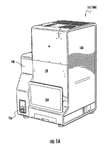
100221 FIG. IA is a perspective view of an instrument, according to
embodiments of the
present invention.
[0023] FIG. 1B is a perspective view of an instrument and a light source,
according to
embodiments of the present invention.
[0024] FIG. 2A illustrates a schematic diagram of an instrument and a light
source, according
to embodiments of the present invention.
[0025] FIG. 2B illustrates a block diagram of the chamber of FIG. 2A,
according to
embodiments of the present invention.
5
CA 03090697 2020-08-06
WO 2019/160792
PCT/US2019/017445
[0026] FIG. 2C illustrates a block diagram of a processor control system of
the instrument of
FIG. 2A, according to embodiments of the present invention.
[0027] FIG. 2D illustrates a block diagram of an example processor and memoiy
that may be
used in accordance with embodiments of the present invention.
[0028] FIGS. 3A-3E illustrate schematic diagrams of an external resistor
coupled to an ion
optics system of the chamber of FIGS. 2A and 2B, according to embodiments of
the present
invention.
[0029] FIGS. 4A-4E illustrate flowcharts of example methods to confirm
ionization or other
charged-particle generation in an instrument, according to embodiments of the
present
invention.
[0030] FIG. 5A illustrates a graph of oscilloscope traces for an instrument
firing on a blank
slide, according to embodiments of the present invention.
[0031] FIG. 5B illustrates a graph of oscilloscope traces for an instrument
firing on a sample
slide, according to embodiments of the present invention.
[0032] FIG. 6 illustrates a partial section perspective view inside the
chamber of FIGS. 2A
and 2B, according to embodiments of the present invention.
[0033] FIG. 7 illustrates a block diagram of a resistor connected to a
processor and a laser
source for the calibration of laser energy and/or laser focusing, according to
embodiments of
the present invention.
[0034] FIG. 8 illustrates a flowchart of example methods for the calibration
of laser energy
and/or laser focusing, according to embodiments of the present invention.
[0035] FIG. 9A illustrates Safe High Voltage (SHV) feedthroughs that can be
used with an
instrument, according to embodiments of the present invention.
[0036] FIG. 9B illustrates an SHV patch cable that can be used with an
instrument, according
to embodiments of the present invention.
DETAILED DESCRIPTION
[0037] The present invention now will be described more fully hereinafter with
reference to
the accompanying drawings, in which illustrative embodiments of the invention
are shown.
Like numbers refer to like elements and different embodiments of like elements
can be
designated using a different number of superscript indicator apostrophes
(e.g., 10, 106, 10",
10").
[0038] During assembly of a mass spectrometry instrument/system, it may be
advantageous
to have a diagnostic to confirm the occurrence of ionization due to, for
example, a MALDI
6
CA 03090697 2020-08-06
WO 2019/160792
PCT/US2019/017445
process. According to embodiments of the present invention, such a diagnostic
may be
provided by using the existing ion optics of the instrument/system as a charge
collection
plate. Moreover, an external Direct Current (DC) power supply may be used to
bias one of
the plates of the ion optics.
100391 FIG. IA and FIG. 1B illustrate an example instrument 10, such as a mass
spectrometer 10M. As shown in FIG. 1A, the instrument 10 includes a housing
10h with a
front wall 10f having a display 10d with a user interface. The housing 10h
also has at least
one sample specimen entry port 10p that can be sized and configured to receive
slides. One
or more ports 10p may be used. Each port 10p can be configured as entry-only,
exit-only, or
as both an entry- and exit-port for specimen slides (e.g., for a sample plate
230 of FIG. 2A)
for analysis.
100401 As shown in FIG. 1B, an instrument 10 may use at least one light source
20,
according to embodiments of the present invention. In some embodiments, the
instrument 10
may be a mass spectrometer 10M, and the housing 10h may include at least one
sample
specimen entry port 10p configured to receive slides for the mass spectrometer
10M. For
example, the mass spectrometer 10M may be a table top mass spectrometer, as
shown by the
table 30. Moreover, one or more portions of the instrument 10 may be
pumped/evacuated via
a vacuum pump 60 to a desired pressure. The vacuum pump 60 and/or the light
source 20
may be on board (e.g., inside) the housing 10h or may be provided as an
external plug-in
component to the instrument 10.
100411 The at least one light source 20 can provide light to generate ions
inside the
instrument 10. For example, the light source 20 may comprise a laser 2OLS that
supplies
laser light to the instrument 10. As an example, the laser 2OLS may be a solid
state laser,
such as an UltraViolet (UV) laser with a wavelength above 320 nanometers (nm).
In some
embodiments, the solid state laser 2OLS can generate a laser beam with a
wavelength
between about 347 nm and about 360 nm. The solid state laser 2OLS can
alternatively be an
infrared laser or a visible light laser.
100421 Moreover, although the terms "light source" and "laser" are used to
discuss examples
herein, the light source 20 may comprise any type of source that generates
charged particles
inside the instrument 10 by supplying light/energy to a target/device inside
the instrument 10.
For example, the light source 20 may be configured to provide one of various
types of pulses
of light/energy to a sample plate 230 (FIG. 2A) in the instrument 10 to
generate a pulse of
charged particles. In some embodiments, the light source 20 and the sample
plate 230 may
7
CA 03090697 2020-08-06
WO 2019/160792
PCT/US2019/017445
collectively (or even individually) be referred to as an "ion source," as
light from the light
source 20 may be directed to the sample plate 230 to generate ions.
100431 FIG. 2A illustrates a schematic diagram of an instrument 10 and a light
source 20.
The instrument 10 includes a chamber 210, which may be an "acquisition
chamber," a
"process chamber," a "vacuum chamber," a "chamber under vacuum," or a "chamber
in
vacuum." Inside the chamber 210 are a sample plate 230 (or other target 230T)
and an ion
optics system 220, which may also be referred to herein as "ion optics" or an
"ion optics
assembly."
100441 The ion optics system 220 may be configured to receive light/energy 20L
from the
.. light source 20, and to direct the light/energy 20L to the sample plate
230. The light/energy
20L can cause the sample plate 230 to generate an ion current 230C, which
passes through
the ion optics system 220, through a flight tube 240, and onto a detector 250.
The ion current
230C may be measured as part of a diagnostic method/mode to confirm ionization
in the
instrument 10. Accordingly, as used herein, the term "diagnostic" refers to a
diagnostic with
respect to the instrument 10 rather than with respect to a patient.
100451 In addition to the ion current 230C, the instrument 10 may, in some
embodiments,
provide photons 260P from a photon source 260 onto the detector 250. As
illustrated in FIG.
2A, the sample plate 230 may be adjacent a first end 210E of the acquisition
chamber 210.
The first end 210E of the acquisition chamber 210 and a second end 250E of the
detector 250
may be on opposite ends/portions of the instrument 10.
100461 FIG. 2B illustrates a block diagram of the chamber 210 of FIG. 2A. The
ion optics
system 220 inside the chamber 210 may include an extraction plate 221 and a
back bias plate
222. Moreover, the ion optics system 220 may include a deflector plate 223. In
some
embodiments, the deflector plate 223 may be omitted or removable from the ion
optics
system 220.
100471 External to the chamber 210 are a resistor 201 and a power supply 202.
The resistor
201 is connectable between (e.g., switchably coupled to) the back bias plate
222 and the
power supply 202. As an example, first and second sides/ends of the resistor
201 may be
connected to the back bias plate 222 and the power supply 202, respectively. A
resistance
value of the resistor 201 may be between 10 kiloOluns (ki1) and 100 MegaOluns
(Me), such
that the resistor 201 is configured to receive ion current 230C generated from
a sample on the
sample plate 230. Accordingly, the measured current that is described herein
is the ion
current 230C that passes through the resistor 201. For example, the ion
current 230C may be
measured by measuring a voltage response across the resistor 201 when the ion
current 230C
8
CA 03090697 2020-08-06
WO 2019/160792
PCT/US2019/017445
passes through the resistor 201, as ion generation inside the chamber 210
results in a change
in voltage and current across the resistor 201. Moreover, the power supply 202
may be
connectable between the sample plate 230 and the resistor 201.
100481 Although some examples herein describe a sample on a sample plate 230,
the light
20L could, in some embodiments, be directed to a test plate or other target
230T instead of
the sample plate 230. Additionally or alternatively, the combination/coupling
of the resistor
201, the power supply 202, and the ion optics system 220 may, in some
embodiments, be
referred to as a "system," such as a diagnostic system. Moreover, as the
resistor 201 is
outside of the vacuum chamber 210, the resistor 201 is typically at
atmospheric pressure. In
some embodiments, however, the resistor 201 may be inside the vacuum chamber
210.
Additionally or alternatively, any electrical component (e.g., an inductor or
a capacitor)
having an impedance can be used in place of the resistor 201, as the resistor
201 is merely
one example of an electrical component having an impedance.
100491 FIG. 2C illustrates a block diagram of a processor control system 270C.
The
processor control system 270C may include one or more processors 270, which
may be
configured to communicate with the light source 20, the resistor 201, the
detector 250, and/or
the photon source 260. For example, operations of the light source 20 and/or
the photon
source 260 may be performed under the control of the processor(s) 270. Also, a
signal from
the resistor 201 (e.g., a signal provided via probes coupled to the resistor
201) may be
processed by the processor(s) 270 to measure the ion current 230C that passes
through the
resistor 201. Moreover, data generated by the detector 250 in response to
receiving ions
and/or photons 260C may be provided to the processor(s) 270 for processing.
The
processor(s) 270 may be internal and/or external to the instrument 10.
100501 FIG. 2D illustrates a block diagram of an example processor 270 and
memory 280
that may be used in accordance with various embodiments of the invention. The
processor
270 communicates with the memory 280 via an address/data bus 290. The
processor 270
may be, for example, a commercially available or custom microprocessor.
Moreover, the
processor 270 may include multiple processors. The memory 280 is
representative of the
overall hierarchy of memory devices containing the software and data used to
implement
various functions as described herein. The memory 280 may include, but is not
limited to,
the following types of devices: cache, ROM, PROM, EPROM, EEPROM, flash, Static
RAM
(SRAM), and Dynamic RAM (DRAM).
100511 As shown in FIG. 2D, the memory 280 may hold various categories of
software and
data, such as an operating system 283. The operating system 283 can control
operations of
9
CA 03090697 2020-08-06
WO 2019/160792
PCT/US2019/017445
the instrument 10. In particular, the operating system 283 may manage the
resources of the
instrument 10 and may coordinate execution of various programs by the
processor 270.
[0052] FIGS. 3A-3E illustrate schematic diagrams of the resistor 201 coupled
to the ion
optics system 220 of FIGS. 2A and 2B. Referring to FIG. 3A, a first side of
the resistor 201
is connected to the back bias plate 222 of the ion optics system 220 and a
second side of the
resistor 201 is connected to the power supply 202. As discussed with respect
to FIG. 2B, the
back bias plate 222 is inside the chamber 210, whereas the resistor 201 and
the power supply
202 are external to the chamber 210. The sample plate 230, which is also
inside the chamber
210, generates ions 2301 that flow toward the back bias plate 222. This flow
of the ions 2301
may be referred to herein as the ion current 230C.
[0053] The extraction plate 221 of the ion optics system 220 may be connected
to ground
(i.e., ground potential) GND. In particular, FIG. 3A illustrates ion behavior
when the
extraction plate 221 is connected to ground GND. A reversal in electric field
direction may
cause ion deceleration to a velocity near zero rather than providing a
velocity in an
opposite/reverse direction. If the extraction plate 221 is instead connected
to power, then it
can provide ion travel to the back bias plate 222, which may also be referred
to herein as a
"charge collection plate."
[0054] The sample plate 230 may be simultaneously connected to ground GND and
to the
power supply 202, which may be configured to supply a voltage under about 1000
Volts (V).
For example, the power supply 202 may be configured to supply a voltage of
about 200 V.
Any voltage between about 30 V and about 1000 V. however, may be supplied. The
sample
plate 230 may be at a single voltage at a given time due to a conductive
coating on the
surface of the sample plate 230. The significance of the ground GND (0 V) is
to reference
the voltage with respect to the other end of voltage source 202.
.. [0055] Referring to FIG. 3B, the resistor 201 may serve as a Current-
Viewing Resistor
(CVR). Based on Ohm's law, the voltage 201V across the resistor 201 is
dependent on the
magnitude of the current. As only a small current is generated during a single
ionization
event, the resistance value of the resistor 201 should be large enough to
facilitate measuring
the voltage 201V response. The resistance value, however, should be small
enough that the
measured voltage 201V will not damage test equipment, including the power
supply 202 that
is used to bias the back bias plate 222. As such, resistance values between
about 10 k52 and
about 100 MO would be appropriate for the resistor 201. For example, the
resistor 201 may
have a resistance value of about 1 M. In some embodiments, the resistance
value may be
between about 100 IS/ and about 100
Moreover, even lower resistance values than 100
CA 03090697 2020-08-06
WO 2019/160792
PCT/US2019/017445
Id/ may be used given sufficient signal filtering, processing, and
amplification of the
measured CVR voltage 201V. Accordingly, a resistance value as low as about 10
kS1 may be
used in some embodiments. The resistance value may be a known/predetermined
value.
100561 FIG. 3B also illustrates probes 310 that can be used to measure the CVR
voltage 201V
across the resistor 201. Each probe 310 may have a resistance and a
capacitance. For
example, each probe 310 may have a 10 MS/ resistance and an 11 picofarad (pF)
capacitance.
100571 Furthermore, the ion current 230C provided from the sample plate 230 to
the back
bias plate 222 may be a time-dependent ion beam current 230C'. Also, FIG. 3B
shows that
the pressure state 210S of the chamber 210 may be in vacuum when the time-
dependent ion
beam current 230C' is generated and the CVR voltage 201V is measured. It may
be
advantageous to perform the current/voltage measurement(s) described herein
without
venting the chamber 210, as venting the chamber 210 may result in multiple
hours of
pumping time to return to vacuum pressures after venting. A further (and
potentially more
important) reason for operating in vacuum is that the ions 2301 may not reach
the charge
collection plate due to the decreased mean free path of the ions 2301 at
higher pressures.
Moreover, in some embodiments, the current/voltage measurement(s) can be
performed using
plates or other hardware separate from the ion optics system 220. Although the
current/voltage measurement(s) may be used for instrument diagnostics, the
current/voltage
measurement(s) may additionally or alternatively be used for calibration
purposes, such as for
laser energy adjustment or focus.
100581 Referring to FIG. 3C, example electrical connections external to the
chamber 210 are
illustrated. Because the connections are external to the chamber 210, it is
possible to provide
the diagnostic mode(s)/method(s) described herein for the instrument 10
without significant
hardware additions. For example, switches 221S and 222S are shown outside of
the chamber
.. 210. The switches 221S and 222S may be relays or other switches, and may be
used to
connect plates inside the chamber 210 to power supplies or to ground GND
outside of the
chamber 210. As an example, FIG. 3C illustrates that the switch 221S selects
whether (e.g.,
selectively connects) the extraction plate 221 is connected to ground GND or
to a pulsed
power supply 330, which may be a 3-5 IciloVolt (kV) pulsed power supply.
Moreover, the
switch 222S selects whether the back bias plate 222 is connected to the
resistor 201 or to a
third power supply 320, which may be a 30-100 V power supply. Accordingly, the
extraction
plate 221 and the back bias plate 222 inside the chamber 210 may be referred
to herein as
being "switchably connectable" to power supplies or to ground GND outside of
the chamber
210 via the switches 221S and 222S, respectively.
11
CA 03090697 2020-08-06
WO 2019/160792
PCT/US2019/017445
[0059] FIG. 3C further illustrates a switch 201S that selects whether to
connect the resistor
201 to the power supply 202. When disconnected from the resistor 201, the
power supply
202 may instead be connected to the detector 250. For example, when the
instrument 10 is
operating in a standard mode (e.g., a sample analysis mode) rather than a
diagnostic mode,
the witches 201S and 2225 may disconnect respective ends of the resistor 201
from the
power supply 202 and the back bias plate 222. Accordingly, the resistor 201
may be referred
to herein as being "switchably connectable" between the back bias plate 222
and the power
supply 202 by the switch 222S and/or the switch 201S.
[0060] The CVR voltage 201V may be measured when the switch 2015 and/or the
switch
2225 connect(s) the resistor 201 between the back bias plate 222 and the power
supply 202.
For example, the CVR voltage 201V may be measured via an external oscilloscope
(e.g.,
using the probes 310 of FIG. 3B) or may be diverted to an internal digitizer
within the
instrument 10 (e.g., a digitizer within a mass spectrometer 10M). Moreover,
operations of
the switches 201S, 221S, and 222S may be controlled by the one or more
processors 270 of
FIGS. 2C and 2D.
[0061] Referring to FIG. 3D, the extraction plate 221 may be connected to a
power supply
340 instead of being connected to ground GND as shown in FIGS. 3A and 3B. The
power
supply 340 is configured to apply a voltage to the extraction plate 221 to
transmit ions 2211
from the extraction plate 221 to the back bias plate 222. The ions 2211 may be
ones of ions
2301 that arrived at the extraction plate 221 by passing from the sample plate
230 through an
aperture in the back bias plate 222. Accordingly, the voltage applied by the
power supply
340 may return the ions 2211 to the back bias plate 222. In some embodiments,
the voltage
supplied by the power supply 340 may be equal in magnitude and opposite in
polarity to the
voltage supplied by the power supply 202 to the back bias plate 222. This may
allow for a
small increase in current that is collected on the back bias plate 222, thus
making the voltage
response across the resistor 201 easier to detect.
[0062] For example, as discussed herein with respect to FIG. 3C, the CVR
voltage 201V
across the resistor 201 may be measured via an external oscilloscope or may be
diverted to an
internal digitizer within the instrument 10. The power supply 340 and the
resistor 201 are
external to the chamber 210 that includes the extraction plate 221.
Accordingly, the
measurement of the CVR voltage 201V while the power supply 340 is applying a
voltage to
the extraction plate 221 may, in some embodiments, be performed via hardware
external to
the chamber 210 with switchable and/or manual/releasable connections to the
inside of the
chamber 210.
12
CA 03090697 2020-08-06
WO 2019/160792
PCT/US2019/017445
100631 Referring to FIG. 3E, a power supply 350 may be connected to the
extraction plate
221 to transmit the ions 2211 of FIG. 3D to the back bias plate 222. In some
embodiments,
the power supply 350 may supply voltages ranging from about 30 V to about 500
V.
Moreover, in some embodiments, the extraction plate 221 and the back bias
plate 222 may be
switchably connectable to the power supply 350. For example, the switches 221S
and 222S
may select whether to connect the extraction plate 221 and the back bias plate
222,
respectively, to the power supply 350. When the instrument 10 is analyzing a
sample, the
extraction plate 221 may be connected to the pulsed power supply 330, and the
back bias
plate 222 may be connected to the power supply 350. On the other hand, when
the
instrument 10 is performing a diagnostic method, the extraction plate 221 may
be connected
to the power supply 350, and the back bias plate 222 may be connected to the
resistor 201.
100641 In some embodiments, the measured ion current 230C may be compared with
a
predetermined threshold ion current value. For example, if the instrument 10
has a
predetermined threshold ion current value that is suitable for mass spectra
generation, the
response of the diagnostic method(s) described herein may be used to
confirm/set ionization.
As an example, for MALDT ionization, the laser pulse energy may be fixed and
the laser spot
size varied, or vice versa, until the predetermined threshold ion current
value is detected via
the resistor 201.
100651 The method(s) described herein may be used for mass spectrometers. Any
system/instrument using charged-particle optics for the acceleration of ion
beams or electron
beams, however, may use the method(s). Such systems/instnunents may include
electron
microscopes, plasma thrusters. X-ray generators, ion beams for medical
treatment, and ion
implanters for semiconductor manufacturing, among others. Accordingly, the
term "charged-
particle optics system," as used herein, is not limited to an optics system
for ions. Similarly,
the instrument 10 described herein may measure "charged-particle current,"
which is not
limited to measuring ion current. Also, the measurement(s) may be performed to
confirm
"charged-particle generation," which is not limited to confirming ionization.
Moreover, for
electron-beam applications, the polarities of the voltages described herein
with respect to ion
applications would be reversed.
100661 FIGS. 4A-4E illustrate flowcharts of methods to confirm ionization, or
other charged-
particle generation, in the instrument 10. In some embodiments, the memory 280
of FIG. 2D
may be a non-transitory computer readable storage medium including computer
readable
program code therein that when executed by the processor 270 causes the
processor 270 to
perform the method(s) of any of FIGS. 4A-4E.
13
CA 03090697 2020-08-06
WO 2019/160792
PCT/US2019/017445
[0067] Referring to FIG. 4A, the methods may include providing/reconfiguring
(Block 411)
the ion optics system 220 so that the ion current 230C inside the chamber 210
of the
instrument 10 can be measured (e.g., measured via the resistor 201 external to
the vacuum
chamber 210). The method shown in FIG. 4A may then include determining (Block
412)
whether the ion current 230C is measurable. Accordingly, ionization in the
instrument 10
may be confirmed based on the operations of Blocks 411 and 412.
[0068] Moreover, if the ion current 230C is measurable (Block 412), then the
method may
include determining (Block 420) whether the ions 2301 are arriving at the
detector 250. On
the other hand, if the ion current 230C is not measurable (Block 412), then
troubleshooting
(Block 413) of ionization mechanism(s) should be performed.
[0069] If the ions 2301 are arriving at the detector 250 (Block 420), then the
method may
include determining (Block 430) whether the detector 250 is operating
properly. On the other
hand, if the ions 2301 are not arriving at the detector 250 or if their
arrival is uncertain (Block
420), then the ion optics system 220 may be provided/reconfigured (Block 421)
to iteratively
measure the ion current 230C at points along a path of the ions 2301.
[0070] The method may then including determining (Block 422) whether it
detects a
measurable ion current 230C that should arrive at the detector 250. If so,
then the method
may include determining (Block 430) whether the detector 250 is operating
properly. On the
other hand, if the method does not detect a measurable ion current 230C that
should arrive at
the detector 250 (Block 422), then troubleshooting (Block 423) of voltages,
mechanical
assemblies, and/or installation of the ion optics system 220 should be
performed.
[0071] If the detector 250 is operating properly (Block 430), then it may be
determined
(Block 440) that the path of the ions 2301 is suitable. Moreover, in some
embodiments,
troubleshooting of other areas of the system/instrument 10 may be performed,
including
electronics troubleshooting and/or vacuum troubleshooting. if, on the other
hand, the
detector 250 is not working properly or the propriety of operation is
uncertain (Block 430),
then the method may include turning on (Block 433) a UV Light Emitting Diode
(LED) in a
pulsed operation. Before turning on (Block 433) the UV LED, the method may
include
determining (Block 431) whether the UV LED is installed. If not, then the UV
LED may be
installed (Block 432). In some embodiments, the UV LED may be the photon
source 260 of
FIG. 2A.
[0072] After turning on (Block 433) the UV LED, the method may include
determining
(Block 434) whether the detector 250 signal pulses during pulsing of the UV
LED. If so,
then the method may include determining (Block 436) whether the signal gain of
the detector
14
CA 03090697 2020-08-06
WO 2019/160792
PCT/US2019/017445
250 is as expected, such as by comparing the signal gain with a threshold
signal gain value.
On the other hand, if the detector 250 does not signal pulse (Block 434)
during pulsing of the
UV LED, then troubleshooting (Block 435) of the detector 250 may be performed.
[0073] If the signal gain of the detector 250 is not as expected (Block 436),
such as by being
below a threshold signal gain value, then the method may include adjusting
(Block 437) the
gain of the detector 250. For example, the method may include varying the
output power of
the UV LED (e.g., by vaiying the diode current) and then adjust the gain of
the detector 250
based on the measured response. If, on the other hand, the signal gain of the
detector 250 is
as expected (Block 436), then operations may proceed to Block 440, which is
described
above herein.
[0074] Referring again to Block 411, the providing/reconfiguring of the ion
optics system
220 may be performed in response to determining (Block 410) that the ions 2301
are not
being generated, or that their generation is uncertain. If, on the other hand,
it is determined
that the ions 2301 are being generated (Block 410), then the method may
proceed directly to
determining (Block 420) whether the ions 2301 are arriving at the detector
250, and the
operations of Blocks 411 and 412 may be omitted. Moreover, in some
embodiments, the
instrument 10 may be a mass spectrometer 10M, and the operation(s) of Blocks
410, 411,
and/or 412 may be performed in response to determining (Block 405) that no
signal is being
generated by the mass spectrometer 10M.
[0075] Referring to FIG. 4B, the method(s) described herein are not limited to
ionization.
For example, the operations of Blocks 411 and 412 of FIG. 4A may be performed
with
respect to various types of charged particles, as indicated by Blocks 411' and
412' of FIG. 4B,
respectively. In particular, FIG. 4B illustrates a method that includes
providing/reconfiguring
(Block 411') electrical connections to a charged-particle optics system 220 of
the instrument
10 while the charged-particle optics system 220 is in a vacuum chamber 210
that is in/under
vacuum pressure. In some embodiments, the providing/reconfiguring operation(s)
of Block
411' may be performed automatically by the method via one or more of the
switches 201S,
2215, and 222S. Additionally or alternatively, one or more electrical
connections may be
manually provided/reconfigured, such as by manually connecting a shorting
cable/plug by
which the extraction plate 221 is connectable to ground GND and/or by manually
disconnecting one or more cables/plugs.
[0076] After the providing/reconfiguring operation(s) of Block 411', the
method may confirm
charged-particle generation in the instrument 10 by coupling (Block 412') the
resistor 201
that is external to the vacuum chamber 210 to charged-particle current 230C
generated in the
CA 03090697 2020-08-06
WO 2019/160792
PCT/US2019/017445
vacuum chamber 210. The operation(s) of Block 412' may also include measuring
an
electrical response by the resistor 201 to the charged-particle current 230C.
In particular, the
charged-particle current 230C passing through the resistor 201 provides the
voltage 201V
response that can be measured. A value of the charged-particle current 230C
may then be
determined using Ohm's law. Moreover, as described herein with respect to FIG.
2B, a
resistance value of the resistor 201 may be between 10 Id/ and 100 M.
100771 The operations of FIG. 4B are not limited to being performed while the
chamber 210
is in/under vacuum pressure. Rather, in some embodiments, a method may include
venting
the system, making the electrical connections at atmospheric pressure, and
then
testing/measuring after the system pumps down.
[0078] Referring to FIG. 4C, the providing/reconfiguring operation(s) of Block
411' of FIG.
4B may include multiple operations. For example, the providing/reconfiguring
(Block 411')
of the electrical connections to the charged-particle optics system 220 may
include
grounding, or applying a voltage to, adjacent ion optics screens or plates of
the charged-
particle optics system 220. As an example, the providing/reconfiguring
operations may
include grounding (Block 411'-2) the extraction plate 221 of the charged-
particle optics
system 220 while the extraction plate 221 is in the vacuum chamber 210. The
providing/reconfiguring operations may also include connecting (Block 411'-3)
a first side of
the resistor 201 to the back bias plate 222 of the charged-particle optics
system 220 while the
back bias plate 222 is in the vacuum chamber 210 and while the resistor 201 is
external to the
vacuum chamber 210. Moreover, the providing/reconfiguring operations may
include
connecting (Block 411'-4) the power supply 202 to a second side of the
resistor while the
power supply 202 is external to the vacuum chamber 210.
[0079] After the operations of Block 411'-2, Block 411'-3, and Block 411'-4,
which can be
performed in any order, the method may include applying (Block 411'-5) a
voltage via the
power supply 202 while the power supply 202 is external to the vacuum chamber
210.
Before the method applies (Block 411'-5) the voltage, the
providing/reconfiguring operations
of Block 411' may include disconnecting (Block 411'-1) a cable attached to a
component of
the charged-particle optics system 220 other than the extraction plate 221 and
the back bias
plate 222. The disconnecting of Block 411'-1 may, in some embodiments, be
performed
before placing the chamber 210 in/under vacuum pressure. Additionally or
alternatively, the
component (e.g., one or more downstream charged-particle optics components)
may be
removed from the charged-particle optics system 220. For example, a deflector
portion/component (e.g., the deflector plate 223) of the charged-particle
optics system 220
16
CA 03090697 2020-08-06
WO 2019/160792
PCT/US2019/017445
may be removed, and the charged-particle current 230C may be measured while
the deflector
portion 223 is absent.
[0080] In some embodiments, the providing/reconfiguring operation(s) of Block
411' may
include providing a first state of electrical connections to the charged-
particle optics system
220, such as by performing one or more of the operations of Block 411'-1,
Block 411'-2,
Block 41 l'-3, and Block 411'-4. Moreover, the state of electrical connections
to the charged-
particle optics system 220 before the providing/reconfiguring operation(s) of
Block 411' may
be a different second state, such as a state that precedes/lacks one or more
of the operations of
Block 411'-1, Block 411'-2, Block 411'-3, and Block 411'-4.
[0081] Referring to FIG. 4D, the operation(s) of Block 412' of FIG. 4B may
include multiple
operations. For example, the operations may include firing (Block 412'-3) the
laser 20 of the
instrument 10 toward the sample plate 230 that is in the vacuum chamber 210,
while the
extraction plate 221 is grounded, while first and second sides of the resistor
201 are
connected to the back bias plate 222 and the power supply 202, respectively,
and while the
.. power supply 202 is applying a voltage. In particular, the laser 20 may
fire toward a sample
that is on the sample plate 230. The method may then include measuring (Block
412'-4), via
the resistor 201, the current 230C generated by the firing the laser 20 toward
the sample. In
particular, the current 230C may be determined based on a measurement of the
voltage 201V
response to the current 230C passing through the resistor 201.
100821 Moreover, the operations may include firing (Block 4 l 2'-1) the laser
20 toward a
blank slide that is free of any samples, and measuring (Block 412'-2), via the
resistor 201, any
current generated by the firing the laser 20 toward the blank slide, before
the firing (Block
412'-3) of the laser 20 toward the sample. For example, the operation(s) of
Block 412'-2 may
include determining whether a measurable current generated by the firing
(Block 412'-1) the
laser 20 toward the blank slide passes through the resistor 201. In some
embodiments, the
respective measurements/results of the operations of Block 412'-4 and Block
412'-2 may be
compared to determine the magnitude/impact of (a) ionization of a sample
relative to (b)
firing on a blank slide. For example, the operations of Block 412'-4 and Block
412'-2 may
measure first and second electrical responses (e.g., voltage responses),
respectively, by the
resistor 201, which may then be compared with each other and/or with
predetermined
value(s). In the case of the blank slide, as an electrical response may not be
measurable, the
absence of a measurable electrical response may be detected. Moreover, in some
embodiments, the operation(s) of Block 412'-1 (and/or Block 412'-2) may be
performed after
the operation(s) of Block 4 l 2'-3 (and/or Block 412'-4).
17
CA 03090697 2020-08-06
WO 2019/160792
PCT/US2019/017445
[0083] Referring to FIG. 4E, the charged particles described with respect to
FIG. 4B may be
the ions 2301. As shown in FIG. 4E, the operation(s) of Block 412' of FIG. 4B
may include
determining (Block 412'-B) a quantity of the ions 2301 generated in the
chamber 210, based
on a comparison (Block 412'-A) of the measured current 230C with a
predetermined value.
.. The operations of FIG. 4E may be performed either in addition to, or as an
alternative to, the
operations of FIG. 4D.
100841 FIG. 5A illustrates a graph of oscilloscope traces for the instrument
10 firing on a
blank slide. As shown in FIG. 5A, the response 501A of the CVR voltage 201V is
flat (i.e.,
not measurable or noticeable) when firing on a blank slide.
.. [0085] FIG. 5B illustrates a graph of oscilloscope traces for the
instrument 10 firing on the
sample slide 230 having samples thereon. In this example, the instrument 10 is
firing on
samples of ATCC 8739 E. coli. As shown in FIG. 5B, the response 501B of the
CVR voltage
201V is measurable/noticeable when firing on the samples. This stands in
contrast with the
flat response 501A when firing on the blank slide in FIG. 5A.
[0086] FIG. 6 illustrates a perspective view inside the chamber 210 of FIGS.
2A and 2B.
This view illustrates the sample plate 230, as well as the extraction plate
221 and the back
bias plate 222.
[0087] In some embodiments, the sample(s) on the sample plate 230 may include
a biosample
from a patient, and analysis of the sample can be carried out by the
instrument 10 to identify
whether a defined protein or microorganism, such as bacteria, is in the sample
for medical
evaluation of the patient. For example, the instrument 10 may be a mass
spectrometer 10M,
and the analysis can identify whether any of about 150 (or more) different
defined species of
bacteria is in a sample, based on obtained spectra. The target mass range can
be between
about 2,000-20,000 Dalton.
[0088] FIG. 7 illustrates a block diagram of a resistor 201 in communication
with
processor(s) 270 and a laser source 2OLS for the calibration of laser energy
and/or laser
focusing. The processor(s) 270 may receive/process data/signals resulting from
an electrical
response by the resistor 201 to current generated by light from the laser
2OLS, and the
processor(s) 270 may responsively control the laser 2OLS to adjust its laser
energy and/or
laser focus. The combination/communication of the processor(s) 270 with the
laser 20L5 and
the resistor 201 to control calibration of the laser 2OLS may provide a laser
calibration system
770C. Moreover, as described herein, the resistor 201 may be coupled to a
power supply
202, which may also be controlled by the processor(s) 270.
18
CA 03090697 2020-08-06
WO 2019/160792
PCT/US2019/017445
[0089] FIG. 8 illustrates a flowchart of example method(s) for the calibration
of laser energy
and/or laser focusing. The method(s) may including coupling (Block 810) the
resistor 201,
which is external to the vacuum chamber 210, to current (e.g., the charged-
particle current
230C) that is generated inside the vacuum chamber 210 by light 20L from the
laser 2OLS.
Accordingly, the term "coupling," as used herein with respect to the resistor
201 and current,
may refer to firing the laser LS at a target 230T that is in the vacuum
chamber 210 to
generate current. Moreover, the method(s) may include adjusting (Block 830)
the laser
energy and/or the laser focus of the laser 2OLS, in response to a measurement
(Block 820) of
an electrical response, such as a voltage 201V response, by the resistor 201
to the current.
For example, the processor(s) 270 may compare a measured electrical response
with a
predetermined value (e.g., a threshold value or range), and perform the
adjusting (Block 830)
in response to deviation from the predetermined value.
[0090] The present invention advantageously provides for directly measuring
the ion current
230C generated from a sample. Conventional systems, by contrast, may only
provide indirect
feedback about ion current based on the intensity of peaks in mass spectra.
Accordingly, in
conventional systems, if no mass spectra are being generated, it may be
difficult to determine
whether ions are being generated, arriving at a detector, and/or resulting in
an output signal
by a detector. The measurement of the current 230C by the present invention,
however, may
be performed when no mass spectra are generated.
[0091] The present invention also advantageously provides for measuring the
ion current
230C without requiring additional hardware (e.g., additional diagnostic
hardware) inside the
chamber 210. Rather, any additional hardware (e.g., the resistor 201, the
power supply 202,
and the switches 2015, 2215, and 222S) used to implement the methods (e.g., as
a diagnostic)
of the present invention for the instrument 10 can be external to the chamber
210.
[0092] FIG. 9A illustrates Safe High Voltage (SHV) vacuum feedthroughs 910
that can be
used with the instrument 10. For example, the SHV feedthroughs 910 may be
PASTERNACKg'PE4500 SHV jack bulkhead hermetically sealed terminal connectors.
In
some embodiments, one of the feedthroughs 910 may be an extraction pulse SHV
feedthrough and another of the feedthroughs 910 may be a back bias SHV
feedthrough.
[0093] FIG. 9B illustrates an SHV patch cable 920 that can be used with the
instrument 10.
For example, the SHV patch cable 920 may be connected between a resistor
measurement
box 201 and the atmospheric side of a back bias SHV feedthrough 910 to connect
one side of
the resistor 201 to the back bias plate 222.
19
CA 03090697 2020-08-06
WO 2019/160792
PCT/US2019/017445
[0094] The following is one non-limiting example of the methods/diagnostic
described
herein. To assist in the troubleshooting of mass spectrometry
instruments/systems, the
following procedure was developed to test the occurrence of ionization at a
sample. An
underlying principle of the procedure involves using a charge collection plate
and a CVR.
Existing connections of the instrument/system are modified so that a lower
removable portion
of the ion optics of the instrument/system may facilitate the diagnostic. The
diagnostic may
include the following operations:
1009511. Set the laser optics positions to those specified in the
instrument/system tuning
procedures.
100961 2. Turn off all high voltages, to protect against damaging the
instrument 10.
100971 3. Vent the vacuum system.
100981 4. Inside the vacuum chamber 210, disconnect all cables attached
to the
removable ion optics 220, with the exception of the back bias and extraction
pulse cables.
The remaining connections should not go through any voltage dividers in the
vacuum
chamber 210. Moreover, ensure that unused cables are not shorted to a wall of
the vacuum
chamber 210.
[0099] 5. Remove the deflector portion 223 of the ion optics assembly
220. Leave the
lower portion of the ion optics assembly 220 in place.
[00100] 6. Close the door and start pumping down the vacuum chamber 210 to
operation
pressure (less than 3x10⁻⁶ Torr).
1001011 7. Disconnect the extraction pulse cable from the atmospheric side
of the
extraction pulse Safe High Voltage (SHV) feedthrough 910.
1001021 8. Attach a shorting plug to the atmospheric side of the
extraction pulse SHV
feedthrough 910. This grounds the extraction plate 221.
1001031 9. Disconnect the back bias cable from the atmospheric side of the
back bias
SHV feedthrough 910.
1001041 10. Connect an SHV patch cable 920 between a resistor measurement box
201 and
the atmospheric side of the back bias SHV feedthrough 910. This connects one
side of the
resistor 201 (e.g., a 10 kV, 1 Watt, 10 Ma +/- 5% resistor) to the back bias
plate 222.
1001051 11. Connect a DC power supply 202 capable of -200 V to the remaining
side of
the resistor measurement box 201. Note that the polarity is negative for the
inner conductor.
It may be desirable to use a power supply that can been controlled via a
Graphical User
Interface (GUI). A benchtop power supply, however, may be used. In some
embodiments, a
power supply of the detector 250 may be used. An adapter or a different
termination may be
CA 03090697 2020-08-06
WO 2019/160792
PCT/US2019/017445
used with the power supply of the detector 250, as this power supply may be
terminated in
Miniature High Voltage (MHV).
1001061 12. Connect standard 10x oscilloscope probes 310 rated for >300 V to
either side
of the resistor 201 in the measurement box. The corresponding channels on the
oscilloscope
may be Alternating Current (AC) coupled.
1001071 13. On the oscilloscope, create a math function to subtract the two
probe voltages.
This creates a differential voltage measurement (the CVR voltage 201V) across
the resistor
201.
1001081 14. Connect a cable to the laser sync output of the laser 20. This may
be achieved
via a test point or connector on the circuit boards. For example, a connector
of a timing
board may be used.
1001091 15. Set the oscilloscope to trigger on the leading edge of the laser
sync signal.
This is shown as a falling-edge trigger in FIG. 5A, but may be different
depending on
electronics design.
1001101 16. Insert a blank slide with no samples into the instrument 10 and
pump down to
operating pressure.
1001111 17. Set all high voltages in the instrument 10 to be 0 V during
acquisition, to
protect against damaging the instrument 10.
1001121 18. Set the DC power supply 202 to -200 V. This may be easier to set
with no
averaging on the oscilloscope.
1001131 19. Set the oscilloscope to average 64 events. The signal may be very
noisy
without averaging. The averaging should make the signal more distinguishable
from noise.
1001141 20. Begin firing the laser 20 on the slide and raster, if possible.
The laser energy
at the slide should be approximately 5 microJoules (0). This was achieved with
a laser
power of 200 from the laser 20. The 5 i.tJ value is based on measurements of
1.5 p..1 at the
sample for 6 1.1.1 from the laser 20. When using a blank slide, the math
function representing
the differential voltage 201V across the resistor 201 should not change at a
laser trigger
event, as shown in FIG. 5A. In FIG. 5A, channel 1 is the voltage of the DC
power supply
202, channel 2 is the laser sync event, channel 3 is the voltage probe 310 on
the power supply
202 side of the resistor 201, and channel 4 is the voltage probe 310 on the
vacuum chamber
210 side of the resistor 201.
1001151 21. Discontinue firing on the blank slide.
21
CA 03090697 2020-08-06
WO 2019/160792
PCT/US2019/017445
[00116] 22. Replace the blank slide with a full slide of ATCC 8739 E. coli and
pump down
to operating pressure. These samples can be from either suspension or manual
deposits. In
some embodiments, fresh samples may be suspended in matrix.
[00117] 23. Set all high voltages in the instrument 10 to 0 V during
acquisition, to protect
against damaging the instrument 10.
[00118] 24. Set the DC power supply 202 to -200 V. This may be easier to set
with no
averaging on the oscilloscope.
100119J 25. Set the oscilloscope to average 64 events. The signal may be very
noisy
without averaging. The averaging should make the signal more distinguishable
from noise.
[00120] 26. Begin firing the laser 20 on the slide and raster, if possible.
The laser energy
at the sample should be approximately 5 microJoules (la). This was achieved
with a laser
power of 20 J from the laser 20. The 5 J value is based on measurements of
1.5 J at the
sample for 6 pi from the laser 20. When using a slide with samples, the math
function
representing the differential voltage 201V across the resistor 201 should
change by
approximately 10 milliVolts (mV) during a laser trigger event, as shown in
FIG. 5B.
[00121] This change in voltage on the CVR 201 is proportional to the ion
current 230C
collected in the instrument 10 via Ohm's law. In FIG. 5B, channel 1 is the
voltage of the DC
power supply 202, channel 2 is the laser sync event, channel 3 is the voltage
probe 310 on the
power supply 202 side of the resistor 201, and channel 4 is the voltage probe
310 on the
vacuum chamber 210 side of the resistor 201.
[00122] 27. Discontinue firing on the E. coli samples.
[00123] 28. Remove the slide of E. coli samples from the instrument 10.
[00124] In the figures, certain layers, components, or features may be
exaggerated for clarity,
and broken lines illustrate optional/removable features or operations unless
specified
otherwise. The terms "FIG." and "Fig." are used interchangeably with the word
"Figure" in
the application and/or drawings. This invention may, however, be embodied in
many
different forms and should not be construed as limited to the embodiments set
forth herein;
rather, these embodiments are provided so that this disclosure will be
thorough and complete,
and will fully convey the scope of the invention to those skilled in the art.
1001251 It will be understood that, although the terms "first," "second," etc.
may be used
herein to describe various elements, components, regions, layers, and/or
sections, these
elements, components, regions, layers, and/or sections should not be limited
by these terms.
These terms are only used to distinguish one element, component, region,
layer, or section
from another region, layer or section. Thus, a "first" element, component,
region, layer, or
22
CA 03090697 2020-08-06
WO 2019/160792
PCT/US2019/017445
section discussed below could be termed a "second" element, component, region,
layer, or
section without departing from the teachings of the present invention.
[00126] Spatially relative terms, such as "beneath," "below," "bottom,"
"lower," "above,"
"upper," and the like, may be used herein for ease of description to describe
one element or
feature's relationship to another element(s) or feature(s) as illustrated in
the figures. It will be
understood that the spatially relative terms are intended to encompass
different orientations of
the device in use or operation in addition to the orientation depicted in the
figures. For
example, if the device in the figures is turned over, elements described as
"below" or
"beneath" other elements or features would then be oriented "above" the other
elements or
features. Thus, the example term "below" can encompass orientations of above,
below and
behind. The device may be otherwise oriented (rotated 90 or at other
orientations) and the
spatially relative descriptors used herein interpreted accordingly.
1001271 The term "about" refers to numbers in a range of +1-20% of the noted
value.
[00128] As used herein, the singular forms "a," "an," and "the" are intended
to include the
plural forms as well, unless expressly stated otherwise. It will be further
understood that the
terms "includes," "comprises," "including," and/or "comprising," when used in
this
specification, specify the presence of stated features, steps, operations,
elements, and/or
components, but do not preclude the presence or addition of one or more other
features, steps,
operations, elements, components, and/or groups thereof. It will be understood
that when an
element is referred to as being "connected" or "coupled" to another element,
it can be directly
connected or coupled to the other element or intervening elements may be
present. As used
herein, the term "and/or" includes any and all combinations of one or more of
the associated
listed items. Moreover, the symbol "1" has the same meaning as the term
"and/or."
[00129] Unless otherwise defined, all terms (including technical and
scientific terms) used
herein have the same meaning as commonly understood by one of ordinary skill
in the art to
which this invention belongs. It will be further understood that terms, such
as those defined
in commonly used dictionaries, should be interpreted as having a meaning that
is consistent
with their meaning in the context of this specification and the relevant art
and will not be
interpreted in an idealized or overly formal sense unless expressly so defined
herein.
[00130] In some embodiments, the mass spectrometer 10M is configured to obtain
an ion
signal from a sample that is in a mass range of about 2,000 to about 20,000
Dalton.
[00131] The term "sample" refers to a substance undergoing analysis and can be
any medium
within a wide range of molecular weights. In some embodiments, the sample is
being
evaluated for the presence of microorganisms such as bacteria or fungi. The
sample,
23
CA 03090697 2020-08-06
WO 2019/160792
PCT/US2019/017445
however, can be evaluated for the presence of other constituents, including
toxins or other
chemicals.
[00132] The term "table top" refers to a relatively compact unit that can fit
on a standard
table top or counter top or occupy a footprint equivalent to a table top, such
as a table top that
has width-by-length dimensions of about 1 foot by 6 feet, for example, and
which typically
has a height dimension that is between about 1-4 feet. In some embodiments,
the
instrument/system resides in an enclosure or housing of 28 inches-14 inches
(W) x 28 inches-
14 inches (D) x 38 inches-28 inches (H). The flight tube 240 may have a length
of about 0.8
meters (m). In some embodiments, longer or shorter lengths may be used. For
example, the
flight tube 240 may have a length that is between about 0.4 m and about 1 m.
[00133] The foregoing is illustrative of the present invention and is not to
be construed as
limiting thereof. Although a few example embodiments of this invention have
been
described, those skilled in the art will readily appreciate that many
modifications are possible
in the example embodiments without materially departing from the novel
teachings and
advantages of this invention. Accordingly, all such modifications are intended
to be included
within the scope of this invention. Therefore, it is to be understood that the
foregoing is
illustrative of the present invention and is not to be construed as limited to
the specific
embodiments disclosed, and that modifications to the disclosed embodiments, as
well as other
embodiments, are intended to be included within the scope of the invention.
24