Note: Descriptions are shown in the official language in which they were submitted.
CA 03090714 2020-08-07
WO 2019/157594 PCT/CA2019/050176
HIGH MELTING POINT METAL OR ALLOY POWDERS ATOMIZATION
MANUFACTURING PROCESSES
CROSS-REFERENCE TO RELATED APPLICATIONS
[0001] The
present application claims the benefit of priority from U.S. provisional
application no. 62/631,286 filed on February 15, 2018. This document is hereby
incorporated
by reference in its entirety.
FIELD OF THE DISCLOSURE
[0002] The
field of the disclosure pertains to the production of fine metallic powders
for application in the electronic industry, metal injection forming, thermal
spraying, thermal
spray welding, 3D printing and catalyst materials.
BACKGROUND OF THE DISCLOSURE
[0003] Many
new materials with outstanding physical and chemical properties can
be synthesized but remain difficult to produce economically at industrial
scale by
conventional methods (casting/machining). Some of these materials are
synthesized or
deposited by alternative techniques such metal injection forming, 3D printing,
thermal
spaying and other techniques requiring powders with specific size
distribution, sphericity
and physical properties.
Electronic devices and components have also been significantly
reduced in size and they also require fine metallic powders in formulations
for solder paste
or ink used to apply conductive materials containing metallic powders. In
brief technology is
advancing and in order to enable more innovative bulk materials, coating,
conductive
layers, metallization and metal forming applications, metallic powders of
relatively fine size
distribution and of relatively tight size distribution are in increasing
demand. Some other
applications of fine powders are also seen in catalytical materials where
selected precious
metals or metals having multiple oxidation states are also used. In this later
case, fine
metallic powders can be produced and dispersed on a media to serve together as
a
catalytical material. It is not uncommon to have required or requested
particle size
distribution mostly under 50 and even under 20 microns for such applications.
[0004] There
are multiple other applications for fine metallic powders, such as metal
injection forming, thermal spraying, thermal spray welding, 3D printing and
many more.
- 1 -
CA 03090714 2020-08-07
WO 2019/157594 PCT/CA2019/050176
[0005] Conventional techniques (atomization, centrifugal disintegration,
water
atomization...) can produce fine powders, butsmaller particle size, low
standard deviation
on size distribution and the spherical shape of the particles are difficult to
achieve from
metals or alloys with these techniques. This often leads to a low recovery of
the produced
powder in a defined size fraction from these technologies.
SUMMARY OF THE DISCLOSURE
[0006] The present disclosure describes a new production process for
metallic
powders having high melting points. This process produces fine spherical
powders with a
small standard deviation on the particle diameter.
[0007] In a first aspect, there is provided a high melting point metal or
alloy powder
atomization manufacturing process comprising:
providing a melt of said high melting point metal or alloy through a feed
tube;
diverting said melt at a diverting angle with respect to a central axis of the
feed tube to obtain a diverted melt;
directing the diverted melt to an atomization area; and
providing at least one atomization gas stream to the atomization area,
[0008] The atomization process may be being carried out in the presence of
water
within an atomization chamber used for said atomization process.
[0009] In a second aspect, there is provided a high melting point metal or
alloy
powder atomization manufacturing process comprising:
providing a melt of said high melting point metal or alloy through a feed
tube;
delivering said melt through a diverter to an atomization area;
providing at least one atomization gas stream to the atomization area;
delivering water to an atomization chamber used for said atomization
process, wherein, prior to being delivered to the atomization area, the melt
is
diverted in the diverter at a diverting angle with respect to a central axis
of the
feed tube.
[0010] In a third aspect, there is provided a a high melting point metal or
alloy
powder atomization manufacturing process comprising:
- 2 -
CA 03090714 2020-08-07
WO 2019/157594 PCT/CA2019/050176
providing a melt of said high melting point metal or alloy through a feed
tube;
directing the melt to an atomization area; and providing at least one
atomization gas stream having an average gas velocity of at least 300 m/s, to
the atomization area, wherein a ratio of the atomization gas to the high
melting point metal in the atomization area is about 5 000 to about 40 000
cm3 of gas per cm3 of metal to atomize, thereby providing a distribution of
powder with an average particle diameter under 50 microns with geometric
standard deviation of lower than about 2.2.
[0011] In a fourth aspect, there is provided a high melting point metal or
alloy powder
atomization manufacturing process comprising:
providing a melt of said high melting point metal or alloy through a feed
tube;
optionally diverting said melt at a diverting angle with respect to a central
axis
of the feed tube to obtain an optionally diverted melt;
directing the optionally diverted melt to an atomization area; and
providing at least one atomization gas stream having a velocity of at least
300
m/s, to the atomization area, wherein a ratio of the atomization gas to the
high
melting point metal in the atomization area is about 5 000 to about 40 000-
cm3 of gas per cm3 of metal to atomize, thereby providing a distribution of
powder particle sizes having geometric standard deviation of lower than about
2.2.
BRIEF DESCRIPTION OF DRAWINGS
[0012] For a better understanding of the various embodiments described
herein, and
to show more clearly how these various embodiments may be carried into effect,
reference
will be made, by way of example, to the accompanying drawings which show at
least one
example embodiment, and in which:
[0013] Figure 1 is a block diagram illustrating steps involved in the
atomization
process, in accordance with at least one embodiment;
[0014] Figure 2 illustrates a schematic side view of an atomization nozzle
with a feed
tube with a diverting channel to provide the melt in the atomization area, in
accordance with
at least one embodiment;
- 3 -
CA 03090714 2020-08-07
WO 2019/157594 PCT/CA2019/050176
[0015] Figure 3 illustrates a perspective view of the atomization chamber
showing
tangential gas entries on the gas inlet, in accordance with at least one
embodiment;
[0016] Figures 4A and 4B illustrate scanning electron microscope (SEM)
pictures of
the powder obtained in Example 2, wherein Figure 4A refers to a Type 5 powder
(15-25
pm) and Figure 4B refers to a the proportion of the powder under 7 pm; and
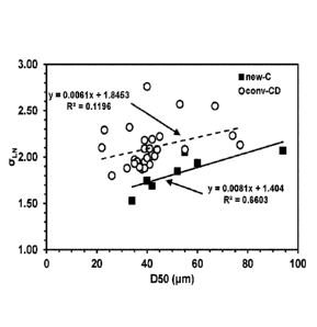
[0017] Figures 5A and 5B illustrate the benefit of the new atomization
technology
(new-C) compared to a reference conventional "Convergent-Divergent (cony-CD)"
atomizer, wherein Figure 5A indicates a lower standard deviation in size
distribution for the
new technology and Figure 5B indicates a higher yield inside a prescribed
particle size
range.
DESCRIPTION OF VARIOUS EMBODIMENTS
[0018] The following examples are provided in a non-limitative manner.
[0019] The expression "high melting point metal" as used herein refers to a
metal
having a melting point temperature of about 500 Celsius to about 1800
Celsius.
[0020] The expression "high melting point alloy" as used herein refers to
an alloy
having a liquidus temperature of about 500 Celsius to about 1800 Celsius.
[0021] Terms of degree such as "about" and "approximately" as used herein
mean a
reasonable amount of deviation of the modified term such that the end result
is not
significantly changed. These terms of degree should be construed as including
a deviation
of at least 5% or at least 10% of the modified term if this deviation would
not negate the
meaning of the word it modifies.
[0022] In understanding the scope of the present disclosure, the term
"comprising"
and its derivatives, as used herein, are intended to be open ended terms that
specify the
presence of the stated features, elements, components, groups, integers,
and/or steps, but
do not exclude the presence of other unstated features, elements, components,
groups,
integers and/or steps. The foregoing also applies to words having similar
meanings such as
the terms, "including", "having" and their derivatives. The term "consisting"
and its
derivatives, as used herein, are intended to be closed terms that specify the
presence of
the stated features, elements, components, groups, integers, and/or steps, but
exclude the
- 4 -
CA 03090714 2020-08-07
WO 2019/157594 PCT/CA2019/050176
presence of other unstated features, elements, components, groups, integers
and/or steps.
The term "consisting essentially of", as used herein, is intended to specify
the presence of
the stated features, elements, components, groups, integers, and/or steps as
well as those
that do not materially affect the basic and novel characteristic(s) of
features, elements,
cornponents, groups, integers, and/or steps.
[0023] In the production of fine metallic powders, there are several
parameters that
can affect product quality. Some of the parameters used to characterize
powders may
include average size distribution, standard deviation of the size
distribution, proportion of
coarser particles and finer particles over/under predefined sizes, sphericity
of the powder,
level of metallic impurities and oxygen level.
[0024] In at least one embodiment, the diverting angle (90-Beta) may be
about 30 to
about 70 degrees.
[0025] In at least one embodiment, the diverting angle may be about 10 to
about 90
degrees.
[0026] In at least one embodiment, an angle formed between the atomization
gas
and the melt may be about 10 to about 90 degrees.
[0027] In at least one embodiment, an angle formed between the atomization
gas
and the melt may be about 40 to about 90 degrees.
[0028] In at least one embodiment, the process may comprise providing a
high
melting point metal.
[0029] In at least one embodiment, the high melting point metal may have a
melting
point of about 500 Celsius to about 1800 Celsius.
[0030] In at least one embodiment, a ratio of the atomization gas to the
high melting
point metal in the atomization area may be about 15 000 to about 30 000 cm3 of
gas per
cm3 of metal to atomize.
[0031] In at least one embodiment, a ratio of the atomization gas to the
high melting
point metal in the atomization area may be about 5 000 to about 40 000 cm3 of
gas per cm3
of metal to atomize.
- 5 -
CA 03090714 2020-08-07
WO 2019/157594 PCT/CA2019/050176
[0032] In at least one embodiment, the high melting point metal may be an
element
chosen from Al, Fe, Ni, Co, Cr, Mn, Si, Ti, Ag, Cu, Mo, Pt, Pd, Au.
[0033] .In at least one embodiment, the high melting point metal may be an
element
chosen from Al, Fe, Ni, Co, Cr, Mn, Si, Ti, Ag, Cu, Mo, Pt, Pd, Au and Sn.
[0034] In at least one embodiment, the high melting point metal is Cu.
[0035] In at least one embodiment, the high melting point metal is Sn.
[0036] In at least one embodiment, the process may include providing a high
melting
point alloy.
[0037] In at least one embodiment, the high melting point alloy may have a
liquidus
of about 500 Celsius to about 1800 Celsius.
[0038] In at least one embodiment, the high melting point alloy may have a
liquidus
of about 500 Celsius to about 1500 Celsius.
[0039] In at least one embodiment, a ratio of atomization gas to the high
melting
point alloy may be about 15 000 to about 30 000 cm3 of gas per cm3 of metal.
[0040] In at least one embodiment, a ratio of atomization gas to the high
melting
point alloy may be about 5000 to about 40 000 cm3 of gas per cm3 of metal.
[0041] In at least one embodiment, the high meting point alloy may include
at least
one element chosen from Al, Fe, Ni, Co, Cr, Mn, Si, Ti, Ag, Cu, Mo, Pt, Pd,
Au.
[0042] In at least one embodiment, the high meting point alloy may include
at least
one element chosen from Al, Fe, Ni, Co, Cr, Mn, Si, Ti, Ag, Cu, Mo, Pt, Pd, Au
and Sn.
[0043] In at least one embodiment, the high meting point alloy comprises
Cu.
[0044] In at least one embodiment, the high meting point alloy comprises
Sn.
[0045] In at least one embodiment, the high meting paint alloy comprises Cu
and Sn.
[0046] In at least one embodiment, the high melting point allow consists
essentially
of Cu and Sn.
[0047] In at least one embodiment, the high melting point allow consists of
Cu and
Sn.
- 6 -
CA 03090714 2020-08-07
WO 2019/157594 PCT/CA2019/050176
[0048] In at least one embodiment, the atomization gas stream may have a
velocity
of about 300 m/s to about 700 m/s.
[0049] In at least one embodiment, the atomization gas stream may have a
velocity
of about 450 m/s to about 600 m/s.
[0050] In at least one embodiment, the atomization gas stream may have a
supersonic speed.
[0051] In at least one embodiment, the atomization gas may be delivered to
an
atomization head through at least one gas inlet oriented in a non-
perpendicular way with
respect to the atomization head, the gas inlet providing a swirl movement in
the atomization
head prior to the gas exit.
[0052] In at least one embodiment, at least two gas injectors may be offset
versus
the central axis of the feed tube, creating a dynamic rotational effect around
the central axis
in the atomization area.
[0053] In at least one embodiment, the process may thereby provide a
distribution of
powder particle sizes with geometric standard deviation of lower than or about
2.2.
[0054] In at least one embodiment, the process may thereby provide a
distribution of
powder particle sizes with geometric standard deviation of about 1.5 to about
2Ø
[0055] In at least one embodiment, the atomization chamber may comprise
about 0
to about 20% of oxygen.
[0056] In at least one embodiment, the water may comprise at least one
additive to
reduce the redox potential of the water.
[0057] In at least one embodiment, the redox potential of the water has
been
reduced prior to the atomization.
[0058] In at least one embodiment, the temperature of the water used in the
atomization chamber is lowered so as to reduce the powders oxidation in the
atomization
process
[0059] In at least one embodiment, the process may thereby provide powder
average particle size of about 10 microns to about 50 microns in diameter.
- 7 -
CA 03090714 2020-08-07
WO 2019/157594 PCT/CA2019/050176
[0060] In at
least one embodiment, the melt of said high melting point metal may be
diverted through at least one melt diverting channel and the diverting angle
may be formed
between the central axis of the feed tube and the at least one melt diverting
channel.
[0061] In at
least one embodiment, the alloy melt may be diverted through at least
two melt diverting channels and the diverting angle may be formed between the
central axis
of the feed tube and the at least two melt diverting channels.
[0062] In at
least one embodiment, at least one jet of water may be sprayed into the
atomization chamber.
[0063] In at
least one embodiment, the at least one jet of water may be sprayed on
at least one wall of the atomization chamber.
[0064] In at
least one embodiment, the process may thereby provide a powder
having an average particle size of less than about 50 microns.
[0065] In at
least one embodiment, the process may thereby provide a powder
having an average particle size of less than about 35 microns.
[0066] In at
least one embodiment, the produced powder may be vacuum dried to
avoid powders oxidation.
[0067] In at
least one embodiment, the produced powder may be washed with an
organic solvent to remove most of the water prior of the drying stage.
[0068] In a
fifth aspect, an atomization device for manufacturing high melting point
metal or alloy powder is provided. The device may include a feed tube for
providing a melt
of said high melting point metal or alloy; a diverter, in fluid flow
communication with said
feed tube, for diverting the melt at a diverting angle with respect to a
central axis of the feed
tube to obtain a diverted melt, and to directing the diverted melt to an
atomization area of
the atomization device; at least one atomization gas injector for providing at
least one
atomization gas stream to the atomization area located inside the atomization
chamber;
and at least one water inlet for providing water within an atomization chamber
of said
atomization device.
- 8 -
CA 03090714 2020-08-07
WO 2019/157594 PCT/CA2019/050176
[0069] In at least one embodiment, the diverter may comprise a melt
diverting
conduit, the diverting conduit being oriented at a diverting angle with
respect to a central
axis of the feed tube.
[0070] In at least one embodiment, the diverter may comprise at least two
melt
diverting conduits, each of the at least two melt diverting conduits being
oriented at a
diverting angle with respect to a central axis of the feed tube.
[0071] In at least one embodiment, the device may comprise at least one gas
inlet,
the at least one gas inlet being non perpendicular to the atomization head as
to provide a
swirl movement in the atomization head and a dynamic rotational movement in
the
atomization area and the atomization chamber.
[0072] In at least one embodiment, at least one non perpendicular gas
inlets may
create a circular flow in the atomization head leading to a dynamic rotational
movement of
the gas in the atomization area and the atomization chamber.
[0073] In at least one embodiment, at least two gas inlets may be non
perpendicular
to the atomization head creating a swirling effect in the atomization head and
a dynamic
rotational effect in the atomization area and the atomization chamber.
[0074] In at least one embodiment, the at least one water inlet may be
located inside
the atomization chamber.
[0075] In at least one embodiment, the at least one water inlet may be
suitable for
providing water for cooling said powder.
[0076] In at least one embodiment, the at least one water inlet may be
suitable for
providing water for transporting said powder to the sieving/drying area.
[0077] In at least one embodiment, the at least one water inlet may be
suitable for
providing water for facilitating sorting/sieving of said powder.
[0078] The described process is based on a known concept, atomization, but
with
several specific improvements. These improvements include changes to the
atomization
head operating parameters, to the atomization chamber configuration and to the
means of
post processing of the powder (collection, sieving and drying) prior of
packing the final
- 9 -
CA 03090714 2020-08-07
WO 2019/157594 PCT/CA2019/050176
product. The process is designed to reach advanced product quality and high
process
performances.
[0079] Figure 1 shows a block diagram 100 of apparatus and steps involved
in the
atomization process, in accordance with at least one embodiment. Figure 1
shows a
melting furnace 102, the atomization nozzle 200, the atomization chamber 108,
a powder
collection system 112 and a sieving system 114.
[0080] Most highmelting point alloys and/or high melting point metals
produced with
this process are sensitive to oxidation, hence the atomization gas may
advantageously be
an inert gas. The system may be generally maintained in near inert conditions
with oxygen
levels much under 21% in the atomization chamber 108. In order to save
operating costs,
this gas may be purified/recycled in the process.
[0081] In at least one embodiment, the atomization manufacturing process
may be
carried out by the atomization nozzle 200 where the atomization gas meets with
a metal
flow in specific conditions described herein. Shown at Figure 1 also shows a
schematic
side view of the atomization nozzle 200, where the molten metal may contact
the
atomization gas in the atomization zone.
[0082] Once the metal has been solidified in fine powders, it is sieved and
packed.
[0083] Referring to Figure 1, some water may be added in the atomization
chamber
108 through the side nozzles 120 and 122 to help collecting the powder and to
bring the
liquid mixture of the powder and water to the sieving area 114. These water
addition side
nozzles 120 and 122 may be oriented towards the atomization chamber walls or
may be
located in the atomization area to help cooling of the powder and to avoid
adhesion/deformation of the particles on the atomization chamber walls. Water
can also be
added to ease powders collection and sieving. The produced powders may then be
sieved
and dried. After collection of the bulk of the powder, from the liquid stream,
the bulk of the
powder passes into filter presses 116 to recover all remaining powders in
suspension prior
to water recycling/disposal.
[0084] The size distribution of the powder produced during the optimization
manufacturing process can be affected by the speed at which the atomization
gas hits the
-10-
CA 03090714 2020-08-07
WO 2019/157594 PCT/CA2019/050176
metal. In this regards, higher velocity of the atomization gas leads to lower
size distributions
of the powder. If the atomization nozzle 200 is not designed properly, a
smaller portion of
the metal will be meeting the atomization gas in the required conditions
(atomization gas
velocity and volume) and larger variations in size and shape of the produced
powder may
be observed. The intimate contact between the high melting point metal/alloy
and the
atomization gas is also important.
[0085] Figure 2 illustrates a schematic side view of an atomization nozzle
200. The
atomization nozzle 200 has a feed tube 210 with a diverting channel 216 to
provide the
melt in the atomization area 230.
[0086] As shown at Figure 2, the atomization nozzle described herein
comprises a
feed tube 210 located between the melting furnace 102 and the atomization area
230
which is equipped with a diverter 216 (also called herein as a diverting
channel 216). The
role of this diverter 216 is to provide a better contact between the metal and
the gas in the
atomization zone 230.
[0087] The metal being hit by the atomization gas stream at a sheer angle
Gamma
defined as Gamma = 90-Beta+Alpha. This approach provides additional parameters
for
improvement of the atomization process: Beta angle, as well as diameter and
number of
diverter channels 216.
[0088] In at least one embodiment, the metal may be diverted in the
atomization
area 230 with the Beta angle being about 20 to about 60 degrees. For example,
the
atomization gas may be provided to the atomization area 230 at an Alpha angle
of about 20
to about 35 degrees.
[0089] For example, if the sheer angle Gamma is about 90 degrees, or at
least about
60 to about 120 , the atomization may be improved, by an enhanced gas to metal
contact
and higher sheer energy
[0090] The melt diverting angle is also defined herein as 90-Beta.
[0091] The Alpha angle, at which the atomization gas may be provided with
respect
to the feed tube 210, may also have other limitations. For example, if angle
Alpha is more
-11 -
CA 03090714 2020-08-07
WO 2019/157594 PCT/CA2019/050176
than 60 degrees, a close to direct projection of the atomization gas on the
atomization
chamber walls may require larger atomization chamber diameters.
[0092] For example, Alpha angle may be as low as about 20 to about 45 .
[0093] For example, Alpha angle may be less than about 20 to about 450.
[0094] In at least one embodiment, the Alpha angle may be between about 0
to
about 90 ; about 10 to about 500; about 15 to about 500; about 20 to about 50
.
[0095] In at least one embodiment, the Alpha angle may be about 20 to about
45
where 2 Alpha may be about 40 to about 90 ). In at least one embodiment, the
Alpha
angle may be about 20 to about 400; about 30 to about 45 .
[0096] Once the metal/alloy is hit by the atomization gas, small particles
are formed.
Collisions between those particles may produce satellites (many particles
connected
together) and may also produce of non-spherical metallic particles, both of
which need to
be avoided and/or reduced or prevented. This may be partially done by
modifying Alpha
and Beta angles, as well as the average atomization gas velocity and the
dispersion factor.
[0097] In order to avoid collision prior to solidification, the density of
particles in the
atomization gas need to be controlled in an appropriate range. For example, if
one cubic
centimeter (cc) of metal is atomized in 10 microns diameter spherical
particles in 1M3 of
atomization gas, the density of particles in the plume is 1,9 Millions/M3. The
use of 5M3 of
gas per cubic centimeter of metal would reduce this density by a factor 5. So
an optimal
range of gas volume per metal volume is critical to avoid collisions and also
to provide the
sheer energy to pulverize the metal in small dropplets and also providing
proper heat
exchange mechanism to solidify the dropplets rapidly. The use of 5000 to 40000
cm3 of
atomization gas per cubic centimeter of metal/alloy was found appropriate for
the
production of fine powders (under 50 microns) of high melting point
metals/alloys.
[0098] Described herein are the velocity and the dispersion as being
critical factors
influencing the atomization results (fineness and avoidance of satellites and
non atomized
metal/alloys).
[0099] In at least one embodiment, the atomization device 150 may include
at least
one non-perpendicular atomization gas inlet 214 with respect to the gas feed
tube axis 212,
- 12 -
CA 03090714 2020-08-07
WO 2019/157594 PCT/CA2019/050176
leading to a rotational movement of the atomization gas stream 240 in the
atomization head
222. In an extreme example embodiment described below, the gas inlets 214
enter in the
atomization head tangentially.
[00100] Figure 3 illustrates a perspective view of the atomization chamber
300
showing tangential gas inlets 311 and 314, in accordance with at least one
embodiment.
This design may allow for an asymmetric atomization plume in dynamic rotation
around a
central axis 312. This configuration of the atomization gas inlets may provide
an improved
particle size distribution compared to an atomizer with perpendicular gas
entries with
respect to the feed tube central axis 312.
[00101] Some high melting point metals/alloys are difficult to solidify. .
If some
particles touch the walls of the atomization chamber 108 and are still
partially molten or
close to their melting points, they can be significantly deformed to reach a
flake-type
morphology, agglomerate and form non spherical particles or satellites
(several particles
connected together). In order to reduce these phenomena, the described
atomization
technology can use water as a cooling media. The water may be injected in
direction of the
atomization chamber walls to provide a film of water carrying the produced
powder. The
film of water may ensure that metallic powders or metal droplets are cooled at
a sufficient
temperature to reduce or avoid the sticking particles, satellites and/or
deformed particles.
The water, in some cases, may provide a controlled level of surface oxidation,
which may
also contribute to have a free flowing powder with an acceptable level of
oxygen in the final
product.
[00102] For example, adding water in the atomization chamber (on walls, in
the upper
part of the atomization chamber or at the bottom of the atomization chamber)
may also
improve material classification. Due to electrostatic forces being enhanced
between fine
particles, it is sometimes hard to separate particles if dry sieving is used.
Some high
melting point alloys/metals powders tend to agglomerate together for many
reasons. For
example, sintering or sticking of the particles and also for electrostatic
reasons as
mentioned above. While the exact reason for agglomeration is not fully known
for all high
melting point/alloys produced, there is a benefit for a wet sieving system for
several alloys.
-13-
CA 03090714 2020-08-07
WO 2019/157594 PCT/CA2019/050176
[00103] The use of water in this process may be counterintuitive, as some
alloying
elements/metals may theoretically oxidize in presence of water. Many elements,
such as
Fe, for example, may even reduce water in absence of dissolved oxygen in
water. For
example, when a low oxygen level is maintained in the atomization chamber, the
oxidation
of the produced powder may be inside acceptable levels. In addition of
controlling the
oxygen in the atmosphere of the atomization chamber, the redox potential and
the
temperature of the water used in the process (for the atomization chamber and
for the
sieving) may be controlled, leading to a reduced kinetic of oxidation.
[00104] Some metallic powders, made of high melting point metals/alloy, may
need a
controlled oxidation to remain free flowing in the final product. Optionally,
oxygen peroxide
or other hydrometallurgical oxidants may be addedin the water to allow a
controlled level of
oxidation. Alternatively, the powder may be left in water at a controlled
temperature for a
given period of time (with or without steering) to allow for a controlled
oxidation of the
powder.
[00105] While a controlled oxidation is beneficial for some products,
overly high levels
may be generally detrimental. Optionally, the redox of the incoming water may
be lowered
to limit oxidation. This can be done by adding additives in the water used in
the atomization
process (in the chamber or in the sieving system) to reduce the level of
oxygen in the final
product. Additives can be reducing agents, like organic additives, such as
ethanol,
methanol, formic acid, acetic acid, methane sulfonic or inorganic reductants.
Redox
potential in water may also be reduced by diverse other means, including but
not limited to
electrochemicals system to treat incoming water, reduction of temperature.
filter with
reactive metal powders.
[00106] In at least one embodiment, the dissolve oxygen in the incoming
water may
be controlled to limit oxidation in the product. In at least one embodiment,
the metal film on
the powder may be reduced by dissolution with mild acid (HCI, organic acids,
etc.). These
may be added in the water to reduce the oxide film formed at the powder
surface.
[00107] One of the final production steps of the process is to dry the
powder. This
step can be performed atmospherically, under vacuum or in an inert gas. Vacuum
allows
the drying process to operate at a lower temperature, hence reducing potential
oxidation
- 14-
CA 03090714 2020-08-07
WO 2019/157594 PCT/CA2019/050176
with the water. Optionally, prior of the drying stage, water can be displaced
from the
powder using an organic solvent in which water is soluble. For example ethanol
and
methanol. After the water has been removed, the powder containing some
residual organic
liquid can be dried to produce a final product with low level of oxygen.
[00108] In at least one embodiment, a high melting point metal or alloy
powder
atomization manufacturing process may include providing a melt of said high
melting point
metal or alloy through a feed tube; diverting said melt at a diverting angle
with respect to a
central axis of the feed tube to obtain a diverted melt; directing the
diverted melt to an
atomization area; and providing at least one atomization gas stream to the
atomization
area. Said atomization process being carried out in the presence of water
within an
atomization chamber used for said atomization process.
[00109] In at least one embodiment, the high melting point metal or alloy
powder
atomization manufacturing process may include providing a melt of said high
melting point
metal or alloy through a feed tube; delivering said melt through a diverter to
an atomization
area; providing at least one atomization gas stream to the atomization area;
delivering
water to an atomization chamber used for said atomization process, wherein,
prior to being
delivered to the atomization area, the melt is diverted in the diverter at a
diverting angle
with respect to a central axis of the feed tube.
[00110] In at least one embodiment, the high melting point metal or alloy
powder
atomization manufacturing process may include providing a melt of said high
melting point
metal or alloy through a feed tube; directing the melt to an atomization area;
and providing
at least one atomization gas stream having an average gas velocity of at least
300 m/s, to
the atomization area, wherein a ratio of the atomization gas to the high
melting point metal
in the atomization area is about 5 000 to about 40 000 cm3 of gas per cm3 of
metal to
atomize, thereby providing a distribution of powder with an average particle
diameter under
50 microns with geometric standard deviation of lower than about 2Ø In at
least one
embodiment, the high melting point metal or alloy powder atomization
manufacturing
process may include providing a melt of said high melting point metal or alloy
through a
feed tube; directing the melt to an atomization area; and providing at least
one atomization
gas stream having an average gas velocity of at least 300 m/s, to the
atomization area,
-15-
CA 03090714 2020-08-07
WO 2019/157594 PCT/CA2019/050176
wherein a ratio of the atomization gas to the high melting point metal in the
atomization
area is about 5 000 to about 40 000 cm3 of gas per cm3 of metal to atomize,
thereby
providing a distribution of powder with an average particle diameter under 435
microns with
geometric standard deviation of lower than about 2.2.
[00111] In at least one embodiment, the high melting point metal or alloy
powder
atomization manufacturing process may include providing a melt of said high
melting point
metal or alloy through a feed tube; directing the melt to an atomization area;
and providing
at least one atomization gas stream having an average gas velocity of at least
300 m/s, to
the atomization area, wherein a ratio of the atomization gas to the high
melting point metal
in the atomization area is about 5 000 to about 40 000 cm3 of gas per cm3 of
metal to
atomize, thereby providing a distribution of powder with an average particle
diameter under
350 microns with geometric standard deviation of lower than about 2Ø In at
least one
embodiment, the high melting point metal or alloy powder atomization
manufacturing
process may include providing a melt of said high melting point metal or alloy
through a
feed tube: directing the melt to an atomization area; and providing at least
one atomization
gas stream having an average gas velocity of at least 300 m/s, to the
atomization area,
wherein a ratio of the atomization gas to the high melting point metal in the
atomization
area is about 5 000 to about 40 000 cm3 of gas per cm3 of metal to atomize,
thereby
providing a distribution of powder with an average particle diameter under 50
microns with
geometric standard deviation of lower than about 2.2.
[00112] A high melting point metal or alloy powder atomization
manufacturing process
may include providing a melt of said high melting point metal or alloy through
a feed tube;
optionally diverting said melt at a diverting angle with respect to a central
axis of the feed
tube to obtain an optionally diverted melt; directing the optionally diverted
melt to an
atomization area; and providing at least one atomization gas stream having a
velocity of at
least 300 m/s, to the atomization area, wherein a ratio of the atomization gas
to the high
melting point metal in the atomization area is about 5 000 to about 40 000-
cm3 of gas per
cm3 of metal to atomize, thereby providing a distribution of powder particle
sizes having
geometric standard deviation of lower than about 2Ø A high melting point
metal or alloy
powder atomization manufacturing process may include providing a melt of said
high
- 16-
CA 03090714 2020-08-07
WO 2019/157594 PCT/CA2019/050176
melting point metal or alloy through a feed tube; optionally diverting said
melt at a diverting
angle with respect to a central axis of the feed tube to obtain an optionally
diverted melt;
directing the optionally diverted melt to an atomization area; and providing
at least one
atomization gas stream having a velocity of at least 300 m/s, to the
atomization area,
wherein a ratio of the atomization gas to the high melting point metal in the
atomization
area is about 5 000 to about 40 000- cm3 of gas per cm3 of metal to atomize,
thereby
providing a distribution of powder particle sizes having geometric standard
deviation of
lower than about 2.2.
[00113] For example, the diverting angle (90-Beta) may be about 30 to about
70
degrees.
[00114] For example, the diverting angle may be about 10 to about 90
degrees.
[00115] For example, an angle formed between the atomization gas and the
melt may
be about 10 to about 90 degrees. For example, an angle formed between the
atomization
gas and the melt may be about 40 to about 90 degrees.
[00116] In at least one embodiment, the process may also include providing
a high
melting point metal.
[00117] In at least one embodiment, the high melting point metal may have a
melting
point of about 500 Celsius to about 1800 Celsius.
[00118] In at least one embodiment, a ratio of the atomization gas to the
high melting
point metal in the atomization area may be about 15 000 to about 30 000 cm3 of
gas per
cm3 of metal to atomize. In at least one embodiment, the ratio of the
atomization gas to the
high melting point metal in the atomization area may be about 5 000 to about
40 000 cm3 of
gas per cm3 of metal to atomize.
[00119] In at least one embodiment, the high melting point metal may be an
element
chosen from Al, Fe, Ni, Co, Cr, Mn, Si, Ti, Ag, Cu, Mo, Pt, Pd, Au. .
[00120] In at least one embodiment, the high melting point metal may be an
element
chosen from Al, Fe, Ni, Co, Cr, Mn, Si, Ti, Ag, Cu, Mo, Pt, Pd, Au and Sn.
[00121] In at least one embodiment, the high melting point metal is Cu.
-17-
PCT/CA2019/050176
13 December 2019 13-12-2019
=
[00122] In at least one embodiment, the high melting point metal is
Sn.
[00123] In at least one embodiment, the process may comprise
providing a high
melting point alloy.
[00124] In at least one embodiment, the high melting point alloy may
have a liquidus
between about 500 Celsius to about 1800 Celsius.
[00125] In at least one embodiment, the high melting point alloy may
have a liquidus
of about 500 Celsius to about 1500 Celsius.
[00126] In at least one embodiment, a ratio of atomization gas to
the high melting
point alloy may be about 15 000 to about 30 000 cm3 of gas per cm3 of metal.
[00127] In at least one embodiment, a ratio of atomization gas to
the high melting
point alloy may be about 5000 to about 40 000 cm3 of gas per cm3 of metal.
[00128] In at least one embodiment, the high meting alloy may
comprise at least one
element chosen from Al, Fe, Ni, Co, Cr, Mn, Si, Ti, Ag, Cu, Mo, Pt, Pd, Au and
Sn.
[00129] In at least one embodiment, the high meting point alloy
comprises Cu and Sn.
[00130] In at least one embodiment, the high meting point alloy
comprises Cu.
[00131] In at least one embodiment, the high meting point alloy
comprises Sn.
[00132] In at least one embodiment, the high melting point allow
consists essentially
of Cu and Sn.
[00133] In at least one embodiment, the high melting point allow
consists of Cu and
Sn.
[00134] In at least one embodiment, the atomization gas stream may
have a velocity
of about 300 m/s to about 700 m/s. In at least one embodiment, the atomization
gas stream
may have a velocity of about 450 m/s to about 600 m/s. In at least one
embodiment, the
atomization gas stream may have a supersonic speed.
[00135] In at least one embodiment, the atomization gas may be
delivered to an
atomization head through at least one gas inlet 314, 311 oriented in a non-
perpendicular
- 18 -
3605898
AMENDED SHEET
CA 3090714 2020-08-08
CA 03090714 2020-08-07
WO 2019/157594 PCT/CA2019/050176
way with respect to the metal feed tube axis 312, providing a swirl movement
of the
atomization gas stream 240 in the atomization head 222 prior to the gas exit.
[00136] In at least one embodiment, at least two gas inlets 311, 314 may be
tangential versus the central axis 312 of the feed tube 310. This
configuration may create a
dynamic rotational effect around the central axis 312 of the atomization plume
in the
atomization chamber 108.
[00137] In at least one embodiment, a distribution of powder particle sizes
with
geometric standard deviation may be lower than or about 2.2. In at least one
embodiment,
a distribution of powder particle sizes with geometric standard deviation may
be of about
1.5 to about 2.2.
[00138] In at least one embodiment, a distribution of powder particle sizes
with
geometric standard deviation may be lower than or about 1.8. In at least one
embodiment,
a distribution of powder particle sizes with geometric standard deviation may
be of about
1.5 to about 2Ø
[00139] In at least one embodiment, the atomization chamber 108 may
comprise
about 0 to about 20% of oxygen.
[00140] In at least one embodiment, the water may comprise at least one
additive to
control the redox potential of the water. Examples of additives comprise but
are not limited
to ethanol, methanol, acetic acid, HCI, H202.
[00141] In at least one embodiment, powder average particle size may be of
about 10
microns to about 50 microns in diameter.
[00142] In at least one embodiment, the melt of the high melting point
metal may be
diverted through at least one melt diverting channel and the diverting angle
is formed
between the central axis of the feed tube and the at least one melt diverting
channel.
[00143] In at least one embodiment, the alloy melt may be diverted through
at least
two melt diverting channels (diverters) 216 and the diverting angle (90 -Beta)
may be
formed between the central axis 212 of the feed tube 210 and the at least two
melt diverting
channels 216.
-19-
CA 03090714 2020-08-07
WO 2019/157594 PCT/CA2019/050176
[00144] In at least one embodiment, at least one jet of water is sprayed
into the
atomization chamber 108.
[00145] In at least one embodiment, the at least one jet of water is
sprayed on at least
one wall of the atomization chamber 108.
[00146] In at least one embodiment, a powder may have an average particle
size of
less than about 50 microns. In at least one embodiment, a powder may have an
average
particle size of less than about 350 microns.
[00147] In at least one embodiment, the produced powder may be dried in
vacuum to
avoid powders oxidation.
[00148] In at least one embodiment, the produced powder may be washed with
an
organic solvent to remove most of the water prior of the drying stage. For
example, the
organic solvent may be ethanol or methanol.
[00149] In at least one embodiment, the atomization device 150 for
manufacturing
high melting point metal or alloy powder includes a feed tube 210 for
providing a melt of
said high melting point metal or alloy; a diverter 216, in fluid flow
communication with said
feed tube 210, for diverting the melt at a diverting angle with respect to a
central axis of the
feed tube 210 to obtain a diverted melt, and to directing the diverted melt to
an atomization
area 230 of the atomization device 150; at least one atomization gas injector
214 for
providing at least one atomization gas stream 240 to the atomization area
located inside
the atomization chamber 108; and at least one water inlet 122 for providing
water within an
atomization chamber 108 of said atomization device 150.
[00150] In at least one embodiment, the diverter 216 may have a melt
diverting
conduit 218, the diverting conduit 218 being oriented at a diverting angle
with respect to a
central axis 212 of the feed tube 210.
[00151] In at least one embodiment, the diverter 216 may have at least two
melt
diverting conduits 218, each of the at least two melt diverting conduits 218
being oriented at
a diverting angle with respect to a central axis 212 of the feed tube 210.
[00152] In at least one embodiment, the atomization device 150 may have at
least
one gas inlet 214 (or 311, 314). The at least one gas inlet 311, 314 of an
exemplary
- 20 -
CA 03090714 2020-08-07
WO 2019/157594 PCT/CA2019/050176
embodiment of the atomization device 300 may be tangential or at least non
perpendicular
to the atomization head 310 to provide a swirl movement of the atomization gas
stream
240, in the atomization head 222 and a dynamic rotational movement of the
atomization
plume in the atomization chamber 108.
[00153] In at least one embodiment, at least one non perpendicular gas
inlets (e.g.
311, 314) with respect to the atomization manifold 310 may create a swirl
movement of the
atomization gas stream 240 in the atomization head 222 leading to a dynamic
rotational
movement of the atomization plume in the atomization chamber 108.
[00154] In at least one embodiment, at least two gas inlets 214 may be non
perpendicular to the atomization head 222 creating a swirling effect in the
atomization head
222 and a dynamic rotational effect in the atomization area 230 and the
atomization
chamber 108.
[00155] In at least one embodiment, the at least one water inlet (e.g. 122
or 120 on
Fig. 1) may be located inside the atomization chamber 108.
[00156] In at least one embodiment, the at least one water inlet (e.g. 122
or 120 on
Fig. 1) may be suitable for providing water for cooling said powder.
[00157] For example, the at least one water inlet (e.g. 122 or 120 on Fig.
1) may be
suitable for providing water for transporting said powder to the
sieving/drying area.
[00158] In at least one embodiment, the at least one water inlet can be
suitable for
providing water for facilitating sorting/sieving of the powder.
[00159] EXAMPLES
[00160] EXAMPLE 1: Copper atomized with different conditions
[00161] In this test, the atomization of pure copper was carried out in a
laboratory
scale atomizer with a batch size of 3 Kg using the atomization manufacturing
process and
the atomization device as described herein. Three different conditions were
tested to
validate the effectiveness of the atomization device and the reproducibility.
-21-
CA 03090714 2020-08-07
WO 2019/157594 PCT/CA2019/050176
[00162] Table
1A shows the atomization conditions used for the four tests
of example 1.
Gas feed Averaged gas Metal feed Gas to metal
Test no
rate, g/sec velocity, m/sec rate, kg/min volume ratio
AG15-20 74 589 3.4 8518
AG15-22 110 635 1.7 25261
AG15-23 145 667 1.3 44455
Table 1A. Atomization conditions applied for three tests of example 1
[00163] The
resulting average particle size and standard deviation are shown below.
In all cases, sigma was below 2.0, which, in combination with the relatively
low D50
obtained, led to very high percentage of particles between 1 to 50 pm. It is
also clear that
increasing the gas to metal volume ratio as well as the gas velocity led to a
decrease of
both D50 and sigma.
Test no D50, pm sigma <50 pm, % >50 pm, %
AG15-20 52 1.84 47 53
AG15-22 40 1.74 66 34
AG15-23 34 1.53 82 18
Table 1B Resulting averaged particle size and standard deviation.
[00164] EXAMPLE 2: Copper
[00165] In
this exemplary test, the atomization of pure copper was carried out in a
large atomizer with a batch size of 15 kg using the atomization manufacturing
process and
the atomization device as described herein.
[00166] Table 2A shows
the atomization conditions of the test of Example 1.
Gas feed Averaged Metal feed Gas to
rate, g/sec Gas rate, kg/min metal
velocity, volume ratio
132 560 m/s 1.5 34750
Table 2A. Atomization conditions applied in the test of Example 1.
- 22 -
CA 03090714 2020-08-07
WO 2019/157594 PCT/CA2019/050176
[00167] The resulting average particle size and standard deviation are
shown below.
Considering the gas to metal volume ration and the average gas velocity used
for this trial,
the D50 and sigma are in quite good accordance with previous results obtained
in a
different atomizer.
050, pm Sigma
48 1.8
Table 2B. Resulting averaged particle size and standard deviation.
[00168] Figures 4A and 4B show SEM pictures of the powder obtained in the
Example
2.
[00169] Morphology as determined with a Malvern Morphology equipment was
measured. The circularity of the powder particles was about 0.992 in the 15-25
microns
size fraction and 0.972 in particles size over 25 microns (the circularity is
1 for perfect
spheres).
[00170] EXAMPLE 3: Copper Atomization
[00171] In the tests of the Example 3 pure copper was atomized with two
different
atomizer to show the benefit of using the novel atomization technology
compared to a
conventional "converging-diverging" gas atomizer. Seven atomizations were
realized with
the new system and compared with +30 atomizations with the conventional
technology.
Results indicated a standard deviation in particle size significantly better
that the
conventional technology leading to much higher recoveries of powders in a
prescribed size
distribution range.
[00172] Figures 5A and 5B illustrate the benefit of the new atomization
technology
(new-C) compared to a reference conventional "Convergent-Divergent (cony-CD)"
atomizer, wherein Figure 5A indicates a lower standard deviation in size
distribution for the
new technology and Figure 5B indicates a higher yield inside a prescribed
particle size
range for the new technology.
- 23 -
CA 03090714 2020-08-07
WO 2019/157594 PCT/CA2019/050176
[00173] EXAMPLE 4: Copper-Tin alloys
[00174] Copper-Tin alloys were atomized using the atomization manufacturing
process and the atomization device as described herein. Table 4A summarizes
the
conditions:
ID Composition Average Gas feed Metal feed Gaz to
metal
gas rate rate (kg/min) volume ratio
velocity (g/s)
AFA153 90% Cu¨ 568 m/s 125 2.5 19197
10% Sn
AFA173 75% Cu¨ 568 m/s 125 2.8 16352
25% Sn
AFA182 65% Cu¨ 568 m/s 125 2.8 16524
35% Sn
Table 4A. Atomization conditions applied in the three tests of Example 4.
[00175] The powders atomized using the above parameters in Table 4A display
log-
normal distributions with the fitting parameters described in Table 4B
ID D50 Sigma
(um)
AFA153 24 1.7
AFA173 24 2.1
AFA182 19 2.2
Table 4B Resulting averaged particle size and standard deviation.
[00176] The embodiments of paragraphs [0012] to [00175] of the present
disclosure
are presented in such a manner in the present disclosure so as to demonstrate
that every
combination of embodiments, when applicable can be made. These embodiments
have
thus been presented in the description in a manner equivalent to making
dependent claims
for all the embodiments that depend upon any of the preceding claims (covering
the
previously presented embodiments), thereby demonstrating that they can be
combined
together in all possible manners. For example, all the possible combination,
when
applicable, between the embodiments of paragraphs [0012] to [00175] and the
processes
of paragraphs [0006] to [0011] are hereby covered by the present disclosure.
-24 -
CA 03090714 2020-08-07
WO 2019/157594 PCT/CA2019/050176
[00177] The scope of the claims should not be limited by specific
embodiments and
examples provided in the disclosure, but should be given the broadest
interpretation
consistent with the disclosure as a whole.
- 25 -