Note: Descriptions are shown in the official language in which they were submitted.
OPTICAL-FIBER-COMPATIBLE ACOUSTIC SENSOR
CLAIM OF PRIORITY
[0001] This application claims the benefit of U.S. Provisional
Patent
Application No. 61/314,090, filed March 15, 2010; U.S. Provisional Patent
Application No.
61/331,303, filed May 4, 2010; and U.S. Provisional Patent Application No.
61/382,385,
filed September 13, 2010.
BACKGROUND
Field of the Invention
[0002] This application relates generally to acoustic sensor
systems, and
more particularly to optical-fiber-compatible acoustic sensor systems.
Description of the Related Art
[0003] Various fiber optic sensor systems have been previously
disclosed
that provide acoustic pressure measurements based on the relative
displacements of the two
mirrors of a Fabry-Perot interferometric cavity. See, e.g., M. Yu et al,
"Acoustic
Measurements Using a Fiber Optic Sensor System," J. Intelligent Material
Systems and
Structures, vol. 14, pages 409-414 (July 2003); K. Totsu et al, "Ultra-
Miniature Fiber-Optic
Pressure Sensor Using White Light Intelferometry," J. Micromech. Microeng.,
vol. 15, pages
71-75 (2005); W.B. Spillman, Jr. et al, "Moving Fiber-Optic Hydrophone,"
Optics Left., vol.
5, no. 1, pages 30-31 (January 1980); K. Kardirvel et al, "Design and
Characterization of
MEMS Optical Microphone for Aeroacoustic Measurement," 42nd AIAA Aerospace
Sciences Meeting and Exhibit, 5-8 January 2004, Reno, Nevada; J. A. Bucaro et
al,
"Miniature, High Performance, Low-Cost Fiber Optic Microphone," J. Acoust.
Soc. Am.,
vol. 118, no. 3, part 1, pages 1406-1413 (September 2005); T.K. Gangopadhyay
et al,
"Modeling and Analysis of an Extrinsic Fabry -Perot Interferometer Cavity,"
Appl. Optics,
vol. 44, no. 16, pages 312-3196 (1 June 2005); and P.J. Kuzmenko,
"Experimental
Performance of a Miniature Fabry -Perot Fiber Optic Hydrophone," Proceedings
of 8th
Optical Fiber Sensors Conference, Monterey, California, January 29-31, 1992,
pages 354-
357; 0. Kilic, M. Digonnet, G. Kino, and 0. Solgaard, "Externalfiber Fabry-
Perot acoustic
-1-
Date Recue/Date Received 2020-08-24
WO 2011/115933 PCT/US2011/028407
sensor based on photonic-crystal mirror," in 18th International Optical Fiber
Sensors
Conference, Cancun, Mexico (2006); 0. Kilic, M. Digonnet, G. Kino, and 0.
Solgaard,
"External fibre Fabry¨Perot acoustic sensor based on a photonic-crystal
mirror," Meas. Sci.
Technol. 18, 3049-3054 (2007); 0. Kilic, M. Digonnet, G. Kino, and 0.
Solgaard,
"Photonic-crystal-diaphragm-based fiber-tip hydrophone optimized for ocean
acoustics," in
19th International Optical Fiber Sensors Conference, Perth, Australia (2008);
0. Kilic, M.
Digonnet, G. Kino, and 0. Solgaard, "Fiber-optical acoustic sensor based on a
photonic-
crystal diaphragm," in 15th International Conference on Solid-State Sensors,
Actuators, and
Microsystems, Denver, CO (2009).
100041 Photonic-crystal slabs (PCSs) are photonic-crystal structures
having a
spatially periodically varying refractive index. A PCS exhibits guided
resonance optical
modes that are strongly confined within the PCS, but are coupled to incident
radiation
through a phase matching mechanism due to the periodically varying refractive
index. These
guided resonance modes are typically manifest in transmission or reflection
spectra as sharp
Fano lineshapes superimposed on a smoothly varying background. See, e.g., M.
Kanskar et
al., "Observation of leaky slab modes in an air-bridged semiconductor
waveguide with a
two-dimensional photonic lattice," Appl. Phys. Lett., vol. 70, page 1438
(1997); V.N.
Astratov et al., "Resonant coupling of near-infrared radiation to photonic
band structure
waveguides," J. Lightwave Technol., vol. 17, page 2050 (1999); and S. Fan and
J.D.
Joannopoulos, "Analysis of guided resonances in photonic crystal slabs," Phys.
Rev. B, vol.
65, page 235112 (2002). Such guided resonance modes have been used previously
as optical
filters or mirrors in light emitting diodes and lasers
SUMMARY
100051 In certain embodiments, an acoustic sensor is provided. The
sensor
comprises a diaphragm comprising a reflective element. The sensor also
comprises an
optical fiber positioned relative to the reflective element such that light
emitted from the
optical fiber is reflected by the reflective element. A first end of the
optical fiber and the
reflective element forms an optical cavity therebetween. The sensor further
comprises a
structural element mechanically coupling the diaphragm and the optical fiber.
The structural
element of certain embodiments comprises a material having a coefficient of
thermal
-2-
Date Recue/Date Received 2020-08-24
expansion substantially similar to the coefficient of thermal expansion of the
optical fiber.
For example, the structural element of certain embodiments comprises silica.
[0006] In
certain embodiments, at least a portion of the light reflected by the
reflective element can propagate into the optical fiber. The first end of the
optical fiber can
comprise a second reflective element. The second reflective element and the
reflective
element can form a Fabry-Perot cavity therebetween. In certain embodiments,
the optical
fiber can comprise fused silica and the structural element can comprise fused
silica. In some
embodiments, the reflective element can comprise a photonic-crystal structure.
Additionally,
the diaphragm of some embodiments can comprise silica. In various embodiments,
the
diaphragm of the acoustic sensor can have a thickness approximately equal to a
distance
between the first end of the optical fiber and the reflective element.
[0007] In
certain embodiments, the acoustic sensor can further comprise a
compensating element comprising silica. The compensating element can be spaced
from the
diaphragm and positioned within the optical cavity. The diaphragm of certain
embodiments
can have a lateral dimension and a ratio of the lateral dimension to the
optical fiber diameter
can be in a range between 1.2 and 8. The diaphragm can have a movable portion
having an
area and a ratio of the area to a cross-sectional area of the optical fiber
can be in a range
between 1.4 and 64.
[0008] . In certain embodiments, the diaphragm can comprise one or more fluid
conduits. One or more fluid conduits can be separate from the reflective
element. In the
acoustic sensor of certain embodiments, the optical cavity can comprise a
liquid. The
acoustic sensor can further comprise at least one generally compressible and
generally elastic
element to increase sensitivity. At least one generally compressible and
generally elastic
element can be a gas bubble.
[0009] In
certain embodiments, an acoustic sensor is provided. The sensor
comprises a reflective element. The sensor further comprises an optical fiber
positioned
relative to the reflective element such that light emitted from the optical
fiber is reflected by
the reflective element. The first end of the optical fiber and the reflective
element form an
optical cavity therebetween. The optical cavity comprises a medium having a
refractive
index change with temperature. In these embodiments, an element within the
optical cavity
-3-
Date Recue/Date Received 2020-08-24
WO 2011/115933 PCT/US2011/028407
has a coefficient of thermal expansion and thickness that compensate the
refractive index
change with temperature.
[0010] In various embodiments, the medium can be water. In these
embodiments,
the element within the optical cavity can comprise silica and can have a
thickness
approximately equal to a distance between the first end of the optical fiber
and the reflective
element. In some embodiments, the element within the optical cavity can be a
diaphragm
mechanically coupled to the reflective element. The element within the optical
cavity can
also be mechanically coupled to the optical fiber.
[0011] In certain embodiments, a method of fabricating an acoustic
sensor is
provided. The method comprises providing a diaphragm. The diaphragm comprises
a
reflective element. The method further comprises positioning an optical fiber
relative to the
reflective element such that light emits from the optical fiber and is
reflected from the
reflective element. Positioning the optical fiber relative to the reflective
element comprises
forming an optical cavity therebetween. The method further comprises
mechanically
coupling the diaphragm to the optical fiber with a structural element. The
structural element
comprises a material having a coefficient of thermal expansion similar to the
coefficient of
thermal expansion of the optical fiber. For example, the structural element
can comprise
silica.
[0012] In certain embodiments, providing a diaphragm comprising a
reflective
element can include providing a photonic-crystal structure as the reflective
element. In these
embodiments, providing a photonic-crystal structure can comprise providing a
photonic-
crystal structure fabricated by photolithography. In various embodiments, the
method of
fabricating an acoustic sensor can further comprise silicate bonding the
diaphragm to the
structural element.
100131 The method of fabricating an acoustic sensor can further
comprise
employing an element comprising silica with the optical cavity. In certain
such
embodiments, the method can further comprise selecting a thickness for the
element
comprising silica approximately equal to a distance between the first end of
the optical fiber
and the diaphragm. The method of certain embodiments can comprise selecting a
diaphragm
-4-
Date Recue/Date Received 2020-08-24
diameter to increase mechanical compliance. The method can further comprise
selecting a
diaphragm cross-sectional area to increase mechanical compliance.
100141 In certain embodiments, the method can further comprise
employing
one or more fluid conduits separate from the reflective element. In some
embodiments, the
method can further comprise employing at least one generally compressible and
generally
elastic element to increase sensitivity. At least one generally compressible
and generally
elastic element can be a gas bubble.
10014a1 In accordance with an aspect of an embodiment, there is
provided an
acoustic sensor system comprising: a first acoustic sensor comprising: a first
reflective
element; and a first optical fiber positioned relative to the first reflective
element such that
light emitted from the first optical fiber is reflected by the first
reflective element, wherein an
end of the first optical fiber and the first reflective element form a first
optical cavity
therebetween, the first optical cavity comprising a liquid medium; a second
acoustic sensor
comprising: a second reflective element; and a second optical fiber positioned
relative to the
second reflective element such that light emitted from the second optical
fiber is reflected by
the second reflective element, wherein an end of the second optical fiber and
the second
reflective element form a second optical cavity therebetween, the second
optical cavity
comprising the liquid medium; and a reservoir comprising the liquid medium and
in fluidic
communication with the first optical cavity and the second optical cavity.
10014b1 In accordance with another aspect of an embodiment, there
is
provided an acoustic sensor comprising: a reflective element configured to
move in response
to changes of pressure applied to the acoustic sensor; an optical fiber
positioned relative to
the reflective element such that light emitted from the optical fiber is
reflected by the
reflective element, wherein an end of the optical fiber and the reflective
element form an
optical cavity therebetween; and a focusing element within an optical path of
the light
emitted from the optical fiber and reflected by the reflective element, the
focusing element
comprising a curved portion of the reflective element..
-5-
Date recue / Date received 2021-12-14
BRIEF DESCRIPTION OF THE DRAWINGS
[0015] Figures 1A-1B schematically illustrate examples of
acoustic sensors
compatible with certain embodiments descnbed herein.
[0016] Figure 2 is a plot of a portion of the response of an
example acoustic
sensor as a function of wavelength for various temperatures.
[0017] Figure 3 is an example plot of the calculated resonance
wavelength
change as a function of temperature for a Fabry-Perot sensor comprising silica
compared to
one comprising silicon.
[0018] Figures 4A-4B schematically illustrate examples of
acoustic sensors
compatible with certain embodiments descnbed herein.
[0019] Figure 5 is a graph showing the variation of the
temperature
sensitivity of the optical path length with respect to different thicknesses
of a fused silica
diaphragm in accordance with certain embodiments descnbed herein.
[0020] Figure 6 shows the reflection spectrum calculated for an
example
photonic-crystal having a square pattern of holes with diameters of 800 nm and
a period of
900 nm, fabricated on a silicon diaphragm of thickness 450 nm.
[0021] Figure 7 shows the calculated change in reflectivity at
1550 nm as a
function of temperature for an example sensor in accordance with certain
embodiments
described herein.
[0022] Figure 8 illustrates the contribution to the resonance
wavelength
change as a function of temperature from various factors.
[0023] Figure 9 schematically illustrates an example of an
acoustic sensor
with fluid conduits in accordance with certain embodiments described herein.
-5a-
Date Recue/Date Received 2020-08-24
WO 2011/115933 PCT/US2011/028407
[0024] Figure 10 shows the finesse of a fiber Fabry-Perot calculated
for varying
reflectivities and cavity lengths in accordance with certain embodiments
described herein.
[0025] Figures 11A-11B schematically illustrate example focusing
elements in
accordance with certain embodiments described herein.
[0026] Figure 12 schematically illustrates an example of an acoustic
sensor
compatible with certain embodiments described herein.
[0027] Figure 13A is an example response curve exhibiting cross-
coupling for a
first sensor in parallel with a second sensor.
[0028] Figure 13B is an example response curve exhibiting cross-
coupling for a
second sensor in parallel with a first sensor.
[0029] Figure 14A is an example response curve exhibiting a reduced or
substantially eliminated cross-coupling for a first sensor in parallel with a
second sensor in
accordance with certain embodiments described herein.
[0030] Figure 14B is an example response curve exhibiting a reduced or
substantially eliminated cross-coupling for a second sensor in parallel with a
first sensor in
accordance with certain embodiments described herein.
[0031] Figure 15 schematically illustrates an example photolithography
fabrication process in accordance with certain embodiments described herein.
[0032] Figure 16 schematically illustrates an example fabrication
process for
producing a backside pattern in accordance with certain embodiments described
herein.
[0033] Figures 17A-17C schematically illustrate example portions of
three
individual wafers and their patterns of holes to be used as building blocks of
the silica
structural element in accordance with certain embodiments described herein.
[0034] Figure 18 schematically illustrates the wafers after they have
been bonded
together and attached to the photonic-crystal structure and the optical fiber
to folin the sensor
head in accordance with certain embodiments described herein.
[0035] Figure 19 schematically illustrates the forces due to phenyl
benzoate in
accordance with certain embodiments described herein.
-6-
Date Recue/Date Received 2020-08-24
[0036] Figures 20A-20B schematically illustrate structures used in a
method that
reduces the arc current used to obtain a good bond between the two elements in
accordance
with certain embodiments described herein.
[0037] Figure 21 is a flowchart of an example method of fabricating an
acoustic
sensor in accordance with certain embodiments described herein.
[0038] Figure 22 schematically illustrates an example acoustic sensor
fabricated
and assembled in accordance with certain embodiments described herein.
[0039] Figure 23A shows a scanning electron micrograph of a top view
of a
fabricated photonic-crystal minor in accordance with certain embodiments
described herein.
[0040] Figure 23B shows a scanning electron micrograph of an angled
view of a
fabricated photonic-crystal mirror in accordance with certain embodiments
described herein.
[0041] Figure 23C is a photograph of a fabricated sensor in accordance
with
certain embodiments described herein.
[0042] Figure 24 schematically illustrates an acoustic
characterization setup to
test example sensors.
[0043] Figure 25 shows the measured coherence between a calibrated
reference
microphone and an example acoustic sensor.
[0044] Figure 26 shows the measured frequency response of an example
sensor.
[0045] Figure 27 shows the measured noise (top curve), optoelectronic
noise
(middle curve), and the noise due to detection electronics (bottom curve) for
an example
sensor.
[0046] Figure 28 shows the measured minimum detectable pressure (MDP)
of an
example sensor with the frequency response shown in Figure 26.
[0047] Figure 29 shows the measured thermal stability of the resonance
wavelengths for a silicon sensor (top curve) and an example silica sensor
(bottom curve).
[0048] Figure 30 shows an example optical acoustic sensor system for
ocean
acoustics in accordance with certain embodiments described herein.
[0049] Figure 31 schematically illustrates an example fabrication
process for
producing a sensor system in accordance with certain embodiments described
herein
-7-
Date Recue/Date Received 2020-08-24
[0050] Figure 32 shows an optical profilometry measurement on an
example
diaphragm in accordance with certain embodiments described herein.
[0051] Figure 33 shows a photograph of an example packaged sensor
system in
accordance with certain embodiments described herein.
[0052] Figure 34 shows an example equivalent circuit formed by various
lumped
elements describing sensor system acoustics and the interfacing with
optoelectronics in
accordance with certain embodiments described herein.
[0053] Figure 35A shows an example calculated response curve of a
first sensor
as a function of frequency calculated with the lumped-element model.
[0054] Figure 35B shows the calculated noise spectrum (solid line)
transferred to
an example diaphragm showing contributions from radiation resistance (dashed
line), hole
resistance (dotted line), and channel resistance (dash-dotted line).
[0055] Figure 35C shows the calculated noise spectrum (solid line)
showing
contributions from the noise coupling from a second sensor (dashed line) and a
third sensor
(dotted line), and optoelectronic noise (dash-dotted line) in an example
sensor system in
accordance with certain embodiments described herein.
[0056] Figure 36A shows the calculated minimum detectable pressure
(MDP) as a
function of frequency on an example diaphragm in accordance with certain
embodiments
with the minimum ambient noise in the sea shown for reference.
[0057] Figure 36B shows the minimum detectable pressure as a function
of
frequency when two parallel sensors are non-operational.
[0058] Figure 37A shows the calculated linearity as a function of
diaphragm
displacement, showing the normalized linearities of the diaphragm displacement
(solid line),
Fabry-Perot response (dashed line), and power coupled back into the optical
fiber (dotted
line).
[0059] Figure 37B shows the total harmonic distortion (THD) as a
function of
pressure amplitude for a first sensor (solid line), a second sensor (dashed
line), and a third
sensor (dotted line) in a sensor system in accordance with certain embodiments
described
herein.
-8-
Date Recue/Date Received 2020-08-24
[0060] Figure 38 show Reynolds number as a function of frequency for
annular
channels for a first sensor (solid line), a second sensor (dashed line), and a
third sensor
(dotted line) in a sensor system in accordance with certain embodiments
described herein.
[0061] Figure 39 schematically illustrates an example setup to
characterize
example sensor systems in accordance with certain embodiments described
herein.
[0062] Figure 40 shows the coherence between a reference sensor system
and an
example sensor system in accordance with certain embodiments described herein.
[0063] Figure 41A shows the measured frequency response for an example
sensor
system (solid line) and a theoretical fit (dashed line).
[0064] Figure 41B shows the measured minimum detectable pressure (MDP)
for
an example sensor system (solid line) and a theoretic fit (dashed line).
[0065] Figure 42 shows the measure power spectrum of an example sensor
system
in accordance with certain embodiments described herein.
DETAILED DESCRIPTION OF EXAMPLE EMBODIMENTS
[0066] Optical acoustic sensing has various important applications.
For example,
for structural health monitoring, acoustic sensors can monitor the health of
massive aerospace
and wind-energy structures. Acoustic sensors can also provide mobile
detection, tracking,
and reporting of submarine contacts at long range in defense applications. As
a further
example, the production from wells and zones within a well in oil and gas
applications can be
monitored and controlled. In yet another example, acoustic sensing can measure
the pressure
of any bodily fluid, used in many medical applications, including life-support
devices.
[0067] Certain embodiments described herein include structures,
elements, or
features which advantageously address one or more issues arising from
previously-disclosed
acoustic sensors which utilize a mechanical diaphragm, a first reflective
element, and a
second reflective element (e.g., one or more photonic-crystal slabs) to
produce a Fabry-Perot
sensor with optical properties which are responsive to acoustic waves (e.g.,
acoustic waves
incident on the sensor from the ambient environment or acoustic waves
generated within the
sensor). Certain embodiments described herein can be practiced by appropriate
modification
of these previously-disclosed acoustic sensors. Examples of such previously-
disclosed
acoustic sensors are described in U.S. Pat. No. 7,526,148, issued on April 28,
2009; U.S. Pat.
-9-
Date Recue/Date Received 2020-08-24
No. 7,630,589, issued on December 8, 2009; U.S. Pat. No. 7,809,219, issued on
October 5,
2010; U.S. Pat. No. 7,881,565, issued on February 1, 2011, and U.S. Pat. Appl.
Publ. No.
2011/0041616. The structures, elements, or features described below can be
used
individually, or can be used with one another in combinations of two or more.
Certain
embodiments described herein can alternatively be practiced by appropriate
modification of
other previously-disclosed acoustic sensor configurations (e.g.,
configurations not
corresponding to those described in U.S. Pat. No. 7,526,148, U.S. Pat. No.
7,630,589; U.S.
Pat. No. 7,809,219, U.S. Pat. No. 7,881,565, and U.S. Pat. Appl. Publ. No.
2011/0041616.
Reduced sensitivity to thermal variation
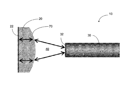
100681 Figures 1A-1B schematically illustrate example acoustic
sensors 10
in accordance with certain embodiments described herein. The acoustic sensor
10 comprises
a diaphragm 20 comprising a reflective element 22. In certain embodiments, the
diaphragm
20 is deflectable by acoustic waves 400 and can comprise silicon, as is
typically used in
acoustic sensors. In certain other embodiments, the diaphragm 20 can
advantageously
comprise silica as will be discussed in more detail below. In yet other
embodiments, the
diaphragm 20 can comprise silicon nitride. Other materials are possible. The
reflective
element 22 of certain embodiments can be positioned (e.g., deposited) on the
diaphragm 20.
In certain embodiments, the reflective element 22 can be bonded directly onto
the diaphragm
20 (e.g., through thermal bonding). In certain embodiments, the reflective
element 22 is
positioned (e.g., deposited or bonded) on a surface of the diaphragm 20 facing
away from the
optical fiber 30, as shown in Figures 1A-1B. However, in other embodiments,
the reflective
element 22 can be positioned (e.g., deposited or bonded) on a surface of the
diaphragm 20
facing towards the optical fiber 30. In still other embodiments, the
reflective element 22 can
be positioned (e.g., found) within the diaphragm 20. In various embodiments,
the diaphragm
20 comprises a reflective element 22 comprising a photonic-crystal structure.
100691 In certain embodiments, the reflective element 22
comprises a
metallic mirror structure (e.g., one or more layers of gold, silver, aluminum,
chromium, or
combinations thereof). In certain embodiments, chromium, e.g., about 2 to
about 5 nm
-10-
Date recue / Date received 2021-12-14
thickness, can be used as an adhesion layer beneath the reflective element 22.
In these
embodiments, the chromium can be relatively absorptive at certain wavelengths
of interest.
The reflective element 22 can further comprise a thin (e.g., between about 10
nanometers to
about 100 nanometers thick) layer of silicon oxide to protect the metal
surface against
oxidation and scratching.
[0070] In certain other embodiments, the reflective element 22
comprises a
dielectric mirror (e.g., multilayer structure comprising a plurality of
transparent dielectric
layers with selected thicknesses and refractive indices to provide a
predetermined
reflectivity). In certain such embodiments, the dielectric mirror can have a
thickness
between 1 micron and 5 microns, and can have an area on the order of square
inches (e.g., a
film stretched across a frame). Examples of dielectric materials compatible
with certain
embodiments described herein include, but are not limited to, silicon dioxide,
magnesium
fluoride, silicon monoxide, and tantalum oxide.
[0071] In certain other embodiments, the reflective element 22
comprises at
least a portion of a photonic crystal structure. The photonic crystal
structure of certain
embodiments comprises one or more photonic crystal slabs. To make a photonic-
crystal slab
in accordance with certain such embodiments, a dielectric layer, such as
silicon or silicon
nitride is deposited on the outer surface of the diaphragm 20, and is
subsequently patterned
with holes going through the dielectric layer. An example process compatible
with certain
embodiments described herein is more fully discussed in U.S. Pat. No.
7,526,148, U.S. Pat.
No. 7,630,589; U.S. Pat. No. 7,809,219, U.S. Pat. No. 7,881,565, and U.S. Pat.
Appl. Publ.
No. U52011/0041616.
[0072] The acoustic sensor 10 further comprises an optical fiber
30
positioned relative to the reflective element 22 such that light emitted from
the optical fiber
30 is reflected by the reflective element 22. The optical fiber 30 of certain
embodiments is a
single-mode fiber. Examples compatible with certain embodiments described
herein include,
but are not limited to, silica-based fiber, SMF-280 fiber available from
Corning Incorporated
of Corning, New York, cutoff shifted fiber, low-water-peak fiber, dispersion-
shifted fiber,
non-zero dispersion-shifted fiber, and non-standard microstructured fiber
(e.g., photonic
crystal fiber).
-11-
Date Recue/Date Received 2020-08-24
[0073] As schematically illustrated by Figures 1A-1B, the optical
fiber 30
comprises a reflective element 32 (e.g., the first end 32 of the optical fiber
30), and the
reflective element 22 and the reflective element 32 of the optical fiber 30
form an optical
cavity 40 therebetween. The reflective element 32 of the optical fiber 30 and
the reflective
element 22 are spaced from one another in certain embodiments by a distance
between 500
nanometers and 50 microns. In certain embodiments, sensors 10 with a smaller
optical cavity
40 can have a more advantageous thermal stability. In certain embodiments, the
optical
cavity 40 comprises a gas (e.g., air), while in certain other embodiments, the
cavity 40
comprises a liquid (e.g., water).
[0074] In certain embodiments, the optical fiber 30 transmits light
from a light
source to irradiate at least a portion of the reflective element 22. Examples
of light sources
compatible with certain embodiments described herein include, but are not
limited to,
monochromatic sources (e.g., laser, laser diode), broadband sources (e.g.,
incandescent lamp,
light-emitting diode), and tunable sources (e.g., tunable laser).
[0075] In certain embodiments, the reflective element 32 of the
optical fiber 30
comprises a metal layer at or on a first end of the optical fiber 30 which is
partially reflective
and partially transmissive to light emitted from the optical fiber 30. In
certain embodiments,
the metal layer comprises multiple sublayers of various materials, examples of
which include,
but are not limited to, chromium, gold, silver, aluminum, and combinations
thereof. In
certain such embodiments, the metal layer further comprises a thin (e.g.,
between about 10
nanometers to about 100 nanometers thick) layer of silicon oxide to protect
the metal surface
against oxidation and scratching. In certain embodiments, the metal layer has
a thickness in a
range between 1 nanometer and 50 nanometers. In certain other embodiments, the
reflective
element 32 of the optical fiber 30 comprises a dielectric mirror at or on the
first end of the
optical fiber 30 comprising a plurality of dielectric material layers.
Examples of dielectric
materials compatible with certain embodiments described herein include, but
are not limited
to, magnesium fluoride, zinc sulfide, silicon dioxide, titanium dioxide, and
tantalum
pentoxide. In certain embodiments, the reflective element 32 of the optical
fiber 30
comprises a photonic crystal structure at or on the first end of the optical
fiber 30.
-12-
Date Recue/Date Received 2020-08-24
[0076] In embodiments where the reflective element 32 of the optical
fiber 30
comprises a partially reflective end of the optical fiber 30, the end of the
optical fiber 30 and
the reflective element 22 of the diaphragm 20 define a Fabry-Perot optical
cavity 40
therebetween. After light propagates out of the optical fiber 30, at least a
portion of the light
reflected by the reflective element 32 propagates back into the optical fiber
30. As an
incident acoustic wave 400 deflects the diaphragm 20, a frequency shift in the
Fabry-Perot
reflection spectrum can be induced. This shift can be detected as a change in
the power
reflected by the Fabry-Perot optical cavity 40 at a fixed wavelength.
[0077] In certain embodiments, one or more factors, other than the
incident
acoustic field that deflects the diaphragm 20 and affects the length of the
optical cavity 40,
can induce a frequency shift in the Fabry-Perot spectrum, and therefore an
error in the
measured acoustic pressure can occur. For example, if the temperature of the
Fabry-Perot
optical cavity 40 slowly increases, the material surrounding the Fabry-Perot
optical cavity 40
can expand. Hence, the spacing of the Fabry-Perot optical cavity 40 can
increase, and the
reflection spectrum can slowly shift. In certain embodiments, this frequency
shift can be
indistinguishable from a slow change in acoustic pressure. Furthermore, since
at the probing
wavelength the rate of change of the reflected power with wavelength (or
optical frequency)
can change as the spectrum shifts, the responsivity of certain embodiments of
the acoustic
sensor 10 to a given displacement of the reflective element 22 can also
change.
[0078] This process is illustrated in Figure 2, which plots a portion
of the
response (reflected power/incident power) of an example acoustic sensor 10 as
a function of
wavelength for various temperatures. As the temperature is increased and the
spectrum shifts
(to the left in Figure 2), the operating (or bias) point at the laser
wavelength (which is fixed),
represented by a dot, shifts from a steep portion of the curve in the
rightmost spectrum (for
highest sensitivity) to a less steep portion. In certain embodiments, this can
be undesirable
because the scale factor of the acoustic sensor 10, which is proportional to
the slope of the
curve, decreases, e.g., the calibration of the sensor response to an acoustic
field decreases.
This can also be undesirable because the scale factor, and hence the response,
can vary.
Because it can vary in an unpredictable manner, the ability of the acoustic
sensor 10 to
perform calibrated measurements of acoustic power can be compromised. An
important
-13-
Date Recue/Date Received 2020-08-24
environmental parameter that results in such an extraneous spectrum shift is
temperature. As
explained above, a variation in the temperature of the medium in which the
acoustic sensor
is located can shift the spectrum. In particular, if the thermal expansion
coefficients of the
optical fiber 30 and the material surrounding the optical cavity 40 are
different, the optical
cavity 40 can experience a length change with temperature variation.
100791 Thus, certain embodiments described herein advantageously
utilize a
structural element mechanically coupling the diaphragm 20 with the optical
fiber 30 and
comprising a material having a similar coefficient of thermal expansion as the
optical fiber
30. For example, in certain embodiments as shown in Figures 1A-1B, the
acoustic sensor 10
comprises a structural element 50 mechanically coupling the diaphragm 20 and
the optical
fiber 30 and surrounding the optical cavity 40, wherein the structural element
50
advantageously comprises a material having a similar coefficient of thermal
expansion as the
optical fiber 30. In certain embodiments, as shown in Figure 1B, the
structural element 50
can include a plurality of elements. Additionally, in certain embodiments as
will be
described more fully below, the structural element 50 can include one or more
holes, fluid
conduits, or channels 55.
100801 In certain embodiments, the optical fiber 30 is made of fused
silica, which
has a small thermal expansion coefficient (e.g., a = 0.55x10⁻⁶/ C), and the
structural element
50 also comprises fused silica. By using a structural element 50 made of the
same low-
thermal-expansion material as is the optical fiber 30, the acoustic sensor 10
is rendered
substantially insensitive to variations in ambient temperature. In certain
embodiments, as
will be discussed below, the optical fiber 30 can be inserted within a
capillary tube. In
various embodiments, the capillary tube can advantageously comprise a material
having a
similar coefficient of thermal expansion as the optical fiber 30. For example,
the material
can be silica.
100811 As shown in Figure 1B, the acoustic sensor 10 of certain
embodiments
further comprises a housing 60 substantially surrounding the diaphragm 20
comprising a
reflective element 22, the structural element 50, the optical cavity 40, and
the optical fiber 30.
In certain embodiments, the housing 60 can comprise a plurality of elements,
e.g., a
protective membrane 61 and a backchamber housing 62. The protective membrane
61 can
-14-
Date Recue/Date Received 2020-08-24
keep the reflective element 22 and the optical cavity 40 isolated from the
environment, e.g.,
to keep contaminants away and to prevent corrosion. The protective membrane 61
can be
configured to allow acoustic waves 400 to propagate across the membrane 61 to
deflect the
diaphragm 20 (e.g. the membrane 61 can comprise a flexible, polymeric
material).
[0082] In certain embodiments, the backchamber housing 62 can surround
a
backchamber or reservoir, 65 that is in fluidic communication with the optical
cavity 40. It
can be mechanically coupled to both the structural element 50 and the optical
fiber 30, as
shown in Figure 1B. In some embodiments, the backchamber housing 62 comprises
brass or
aluminum. In other embodiments, the backchamber housing 61 advantageously
comprises a
material with a similar coefficient of thermal expansion as the optical fiber
30 and/or
structural element 50 for similar reasons discussed above. Thus, the
backchamber housing
62 can comprise silica.
[0083] Figure 3 is an example plot of the resonance wavelength change
as a
function of temperature for a Fabry-Perot sensor 10 with a sensor head
comprising silica in
accordance with certain embodiments described herein compared to one
comprising silicon,
using a probing wavelength of 1550 nm. As shown in Figure 3, the all-silica
sensor 10 (e.g.,
silica fiber 30, silica capillary tube, and silica structural element 50) of
certain embodiments
offers a substantial enhancement in thermal stability as compared to the
sensor comprising
the silica fiber and the silicon sensor head.
[0084] In certain embodiments, the effects of thermal expansion on the
sensitivity
of the acoustic sensor 10 are at least a factor of 10 smaller than other
effects on the sensitivity
of the acoustic sensor 10. Simulations show that with suitable design, the
sensitivity of
certain embodiments of the acoustic sensor 10 does not change by more than 10%
for a
temperature variation of greater than 100 C. Assuming that the Fabry-Perot
cavity 40 is
filled with air, for a Fabry-Perot cavity 40 with a 10- m mirror spacing and a
finesse of 30,
the temperature change that changes the sensitivity of the sensor 10 by 10% is
300 C. The
finesse F of a Fabry-Perot cavity is defined as F = 27EN, where N is the
number of round trips
when the loss factor becomes 1/e. In other words, the energy inside the cavity
drops to 1/e of
its initial value after N round trips. The temperature change is approximately
inversely
proportional to the finesse, so that, e.g., a sensor 10 having an air-filled
Fabry-Perot cavity 40
-15-
Date Recue/Date Received 2020-08-24
with a mirror spacing of 10 gm and a finesse of 300 can tolerate a maximum
temperature
change of around 30 C for a sensitivity variation of no more than 10%.
[0085] For a Fabry-Perot cavity 40 containing water, thermal
variations of the
refractive index of water can have further detrimental effects on the
performance of certain
embodiments of the optical-fiber-compatible acoustic sensor 10. In certain
embodiments in
which the sensor 10 of Figure 1B is employed in water as a hydrophone, the
Fabry-Perot
cavity 40 is filled with water. This water can be either the ambient water in
which the sensor
or hydrophone head is immersed, or a separate reservoir of water isolated from
the
ambient water by an enclosure, such as the protective membrane 61. The
refractive index of
water varies with temperature, more so than does the refractive index of air,
and its effect on
the thermal sensitivity of the sensor 10 is about one order of magnitude
larger than the effect
of the thermal expansion of silica (the dn/dT coefficient of water is
¨11.8x10l6/ C for optical
wavelengths around 1550 nm).
[0086] In a sensor 10 as schematically illustrated by Figures 1A-1B,
the
maximum tolerable temperature change for a cavity filled with water is
generally smaller by a
factor of 15 than the maximum tolerable temperature change for a cavity filled
with air. For
example, for a 10-gm water-filled Fabry-Perot cavity 40 with a finesse of 30,
the temperature
change which changes the sensitivity of the sensor 10 by 10% is only 20 C.
This temperature
change is approximately inversely proportional to the finesse, so that, e.g.,
a sensor 10 having
a cavity 40 with a finesse of 300 can tolerate a maximum temperature change of
only 2 C for
a sensitivity variation of no more than 10%.
[0087] Certain embodiments described herein advantageously compensate
for the
refractive index change of water with temperature. Figure 4A schematically
illustrates an
example of an acoustic sensor 10 compatible with certain embodiments described
herein.
The acoustic sensor 10 comprises a reflective element 22. The acoustic sensor
10 further
comprises an optical fiber 30 positioned relative to the reflective element 22
such that light
emitted from the optical fiber 30 is reflected by the reflective element 22.
The reflective
element 32 of the optical fiber 30 and the reflective element 22 define an
optical cavity 40
therebetween. The optical cavity 40 comprises a medium having a refractive
index change
with temperature. The acoustic sensor 20 further comprises a compensating
element 25
-16-
Date Recue/Date Received 2020-08-24
positioned within the optical cavity 40 and having a coefficient of thei
'nal expansion and
thickness. In certain embodiments, the coefficient of thermal expansion and
the thickness are
selected such that the compensating element 25 compensates the refractive
index change with
temperature of the medium. In certain such embodiments, this compensation is
sufficient for
the optical sensor to have reduced thermal variation in performance as
compared to an optical
sensor without the compensating element.
[0088] The
compensating element 25 can comprise one or more pieces of material
that are selected to provide a coefficient of thermal expansion and total
thickness so that the
sensor 10 has a reduced sensitivity to temperature variations. As shown in
Figure 4A, the
compensating element 25 within the optical cavity 40 comprises of material
spaced away
from the diaphragm 20. Such a material can be part of the first end 32 of the
optical fiber 30.
For example, the material can be attached to the reflective end of the optical
fiber 30 before
the optical fiber 30 is inserted into the sensor head. In certain embodiments
in which the
reflective element 32 of the optical fiber 30 is spaced along the optical
fiber 30 and away
from the end of the optical fiber 30, the compensating element 25 can comprise
the portion of
the optical fiber 30 between the reflective element 32 and the end of the
optical fiber 30.
Alternatively, at least a portion of the compensating element 25 can be formed
by micro-
fabrication such that it is positionable partway between the reflective
element 32 of the
optical fiber 30 and the reflective element 22. For example, at least a
portion of the
compensating element 25 can be on the diaphragm 20 facing the optical fiber 30
(or can be
mechanically coupled to another portion of the optical sensor 10 (e.g., the
structural element
50).
[0089] In
certain embodiments, as shown in Figure 4B, at least a portion of the
diaphragm 20 can serve as the compensating element 25 within the optical
cavity 40. In
accordance with certain such embodiments in which the diaphragm 20 comprises
silica, the
compensating element 25 within the optical cavity 40 has a thickness (labeled
S in Figure 4B)
substantially equal to the spacing between the fiber end 32 and the diaphragm
20 (labeled W
in Figure 4B). The reflective element 22 can be a material coated or
fabricated on the
diaphragm 20. The spacing volume is filled with water, and light is reflected
from the
reflective element 22 on the side of the diaphragm 20 facing away from the
optical fiber 30.
-17-
Date Recue/Date Received 2020-08-24
As discussed above, the reflective element 22 can comprise layers of metals,
dielectrics, or
photonic-crystal structure formed, deposited, or bonded on the diaphragm 20.
[0090] For a
given temperature change, the refractive index of fused silica
changes by approximately the same magnitude as for water, but in the opposite
direction (the
dn/dT coefficient of fused silica is about +12.8x 10-61 C for optical
wavelengths around 1550
nm while dn/dT for water is about -12.8x10⁻⁶/ C for these optical
wavelengths). Therefore,
in certain such embodiments, when light propagates by approximately equal
distances
through water and silica, the temperature effect on the refractive index of
water is effectively
cancelled out by the temperature effect on the refractive index of silica.
Figure 5 is a graph
showing the variation of the temperature sensitivity of the optical path
length (physical length
multiplied by the refractive index) with respect to different thicknesses of
the fused silica
diaphragm 20. Figure 5 corresponds to the spacing between the reflective tip
of the fiber 32
and the diaphragm 20 (labelled "W" in Figure 4B) being held constant at 10 gm,
and the
diaphragm thickness (labelled "S" in Figure 4B) being varied from 6 p.m to 10
m, with the
total optical thickness (T=S+W) being varied from 16 tim to 20 pm. The
absolute value of
the temperature sensitivity of the optical path length the light travels in
the cavity versus
diaphragm thickness (plotted as the solid curve) is significantly below the
absolute value of
the temperature sensitivity for a non-silica diaphragm (shown in Figure 5 as
the dash-dot line)
and is below a maximum practical temperature sensitivity (shown in Figure 5 as
the dotted
line) for the entire range of diaphragm thicknesses between about 6.15 j.tm
and 10 gm. A
minimum temperature sensitivity is observed for a diaphragm thickness of about
8.15 gm,
corresponding to a sensor 10 in which the refractive index variations and
material expansions
compensate each other, such that the sensor 10 is rendered substantially
insensitive to
temperature variations. In certain embodiments, for a practical range of
diaphragm
thicknesses, a sensor 10 or hydrophone having a water-filled cavity and
employing a silica
diaphragm 20 is even less sensitive to temperature than is the sensor 10 upon
having an air-
filled cavity (shown in Figure 5 as the dashed line). The relationship between
the
temperature sensitivity dn/dT of the optical path length with respect to
different thicknesses
for the compensating element can be determined for other materials for the
compensating
element and for other media for the optical cavity.
-18-
Date Recue/Date Received 2020-08-24
[0091] In certain embodiments, the diaphragm thickness is selected to
render a
sensor with a water-filled cavity substantially insensitive to thermal
effects. For example, in
certain embodiments in which the sensor comprises a 10-gm water-filled cavity
between the
diaphragm 20 and the optical fiber 30, the diaphragm thickness is in a range
between about 5
gm and about 12 gm, between about 7 gm and about 10 gm, or between about 8 gm
and
about 9 gm. In certain embodiments, the ratio of the thickness of the
diaphragm 20 to the
cavity size between the diaphragm 20 and the optical fiber 30 is in a range
between about 0.5
and about 1.2, between about 0.7 and about 1, or between about 0.8 and about
0.9. The value
of the diaphragm thickness of 8.15 gm denoted in Figure 5 for the 10-gm water-
filled cavity
is based on an assumption that the light is directly reflected from the
reflective element 22 on
the outer surface of the diaphragm 20. This assumption is accurate for certain
embodiments
when metal layers are used as the reflective element 22. When dielectric
mirrors or photonic
crystals (which can range in thickness approximately from 0.5 gm to 5 gm) are
used,
however, light travels beyond the outer surface of the diaphragm 20 into the
reflective
element 22 before it is reflected. Therefore, to compensate for thermal
expansion and
refractive index changes with temperature of the reflective element 22, the
diaphragm
thickness can be adjusted to obtain the optimum temperature insensitivity for
a given
reflective element 22.
[0092] Because the mechanical compliance of a thick diaphragm 20
(e.g., a
thickness of 8.15 gm) is low, it can be difficult to deflect such a diaphragm
20 in certain
embodiments. In certain embodiments, this issue can be resolved by increasing
the diameter
of the diaphragm 20 to increase the mechanical compliance, as described more
fully below.
[0093] Another issue regarding the example configuration schematically
illustrated in Figure 4B could be the reflection from the surface 21 of the
silica diaphragm 20
facing towards the optical fiber 30. However, due to the small difference
between the
refractive indices of silica and water (nsilica = 1.444 vs. fl
water = 1.316 at 1550 nm wavelength),
the reflection (R) from a silica-water interface, hence from the diaphragm
surface 21, can be
negligible (R < 0.3%). In certain embodiments, this reflection can also be
eliminated or
reduced sufficiently by depositing an anti-reflection coating on the surface
21 of the
diaphragm 20.
-19-
Date Recue/Date Received 2020-08-24
[0094] In embodiments where the reflective element 22 comprises a
photonic-
crystal minor, the thermal response of the photonic-crystal mirror is another
factor that
affects the thermal stability of the sensor 10. As the temperature changes,
the refractive
index of the materials of the photonic-crystal mirror change, and so do its
physical
dimensions, (e.g., the thicknesses of the materials, and the periodicity and
the diameter of the
periodic structures, such as holes). Since all of these parameters affect the
reflection
spectrum of the photonic-crystal mirror, as these parameters change, the
spectrum also
changes. As a result of the change in the reflectivity of the photonic-crystal
mirror, the
finesse of the Fabry-Perot optical cavity 40 changes, and so does the slope of
its reflection
spectrum, in particular at the optimum bias point shown in Figure 2, and the
scale factor of
the sensor 10.
[0095] Finite-difference-time-domain (FDTD) simulations of the effect
of
temperature on the reflection spectrum of the photonic-crystal mirror show
that this
contribution is small for certain application. For example, Figure 6 shows the
reflection
spectrum calculated for an example photonic-crystal structure having a square
pattern of
holes with diameters of 800 nm and a period of 900 nm, fabricated on a silicon
diaphragm 20
of thickness 450 nm. These parameters were selected to obtain a high
reflection at 1550 nm,
a convenient target wavelength for this type of sensor. This photonic-crystal
design provides
¨99 % reflectivity at 1550 nm and a bandwidth of 48 mu for 99 % reflectivity.
[0096] Using the same FDTD method, the spectrum of the same photonic-
crystal
structure can be simulated at different temperatures, taking into account the
changes in
refractive index, in hole radius, in period, and in thickness of the
diaphragm. Figure 7 shows
the calculated change in reflectivity at 1550 nm as a function temperature for
a sensor 10 in
accordance with certain embodiments described herein. For a predetermined
range of
temperatures, e.g., from about 20 C up to a maximum simulated temperature of
about 80 C,
the reflectivity remains within 0.02 % of its value at 20 C. The bandwidth of
the photonic-
crystal structure for 99 % reflectivity, not shown in Figure 7, remains within
2.1 % over this
temperature range. In certain embodiments, the reflectivity remains within
0.03 %, 0.04 %,
0.05 %, 0.08 %, or 0.10 % of its value at 20 C over a range of temperature of
about 20 C to
about 80 C.
=
-20-
Date Recue/Date Received 2020-08-24
[0097] The
result of this small variation in the photonic-crystal reflectivity is that
the resonance wavelength of the sensor remains within 0.02 nm over a 400 C
temperature
range assuming a 90 % reflectivity for the reflecting element 32 at the end 32
of the optical
fiber 30, which translates into a nominal finesse for the Fabry-Perot optical
cavity of 96.
[0098] Another
contribution to the thermal instability of the Fabry-Perot-based
acoustic sensor 10 is thermally induced variations in the refractive index of
the optical cavity
40, e.g., the intra-cavity medium. When this medium is air, as in the case of
a microphone
for example, this contribution can be negligible. However, when it is water,
as may be the
case in a hydrophone, a change in this refractive index can induce an
additional shift in the
resonance of magnitude:
r AA An (1)
Lum n
[0099] In the
case of water, the shift in resonance wavelength due to this effect
stays within +1 nm, thus provides enough stability over 100 C before the
maximum
responsivity drops by more than 10 % for a Fabry-Perot cavity of length 10
p.m. This shift
can be acceptable for many applications.
[0100] Figure 8
illustrates the contribution from each individual factor described
above: thermal expansion of silica (TB), thermally induced variation of the
intra-cavity
medium refractive index (RIM), and thermally induced variation in the spectral
response of
the photonic-crystal mirror (PC). Figure 8 also shows the resonance wavelength
change with
temperature resulting from the sum of these three effects. Because the intra-
cavity medium is
taken to be water in this analysis, and because water has a negative thermo-
optic coefficient,
the contribution of the intra-cavity medium refractive index can be negative,
e.g., its sign is
opposite that of the other two contributions, hence it partially cancels them.
A different
choice of materials and/or design parameters could tailor the amount of
cancellation and total
contribution.
[0101] In
certain embodiments, the material for the medium of the optical cavity
40 can be advantageously selected for improved theonal stability. In addition
to the length of
the optical cavity 40, the thermal modulation of the refractive index of the
medium of the
optical cavity 40 also can contribute to the thermal stability of the sensor
10. For example,
-21-
Date Recue/Date Received 2020-08-24
L = q¨: oc nL (2)
For no resonance shift:
a (nL) az, , an , an
¨ U n¨ + L¨nLasio2 +, ¨ = u (3)
aT aT aT aT
an 1 an
Tla5i02 =---
n aT
where L is the length of the optical cavity 40, n is the refractive index of
the cavity medium,
and a5i02 is the thermal expansion coefficient of silica. In certain
embodiments, this effect
can be exploited for thermal stability. For example, in various embodiments,
the effect of the
thermal expansion of the silica structural element 40 and the refractive index
modulation of
the medium of the optical cavity 40 cancel each other if the right material is
selected for the
cavity medium. For example,
Ian
= a Si02
n aT = 0.5 5 x 1 0-6/ C (4)
Thus, in certain embodiments, the medium for the optical cavity 40 can be
selected for
improved thermal stability.
Increased lateral dimension or area of the diaphragm
[0102] As
mentioned above, a thicker diaphragm 20 is generally
mechanically less compliant than is a thinner diaphragm 20. In addition, one
of the strongest
damping effects that can limit the sensitivity of the sensor 10 is squeeze-
film damping, which
is due to the water forced out of the cavity 40 by the moving diaphragm 20, as
is described
more fully in U.S. Pat. No. 7,526,148, U.S. Pat. No. 7,630,589; U.S. Pat. No.
7,809,219, U.S.
Pat. No. 7,881,565, and U.S. Pat. Appl. Publ. No. 2011/0041616.
[0103] Certain
embodiments described herein restore the compliance of the
diaphragm 20 by increasing the diaphragm diameter (e.g., by approximately a
factor of 5) or
the diaphragm area (e.g., by approximately a factor of 25). Such a significant
increase in the
diaphragm diameter or area also reduces the squeeze-film damping significantly
(e.g., by
approximately a factor of 25), since the relative area of the end face of the
optical fiber 30 to
the area of the diaphragm 20 is reduced. In certain embodiments, the ratio of
the diaphragm
-22-
Date Recue/Date Received 2020-08-24
diameter to the end diameter of the optical fiber 30 is in a range between 1.2
and 8, in a range
between 1.5 and 6, or in a range between 2 and 5. In certain embodiments, the
ratio of the
diaphragm area to the area of the end face of the optical fiber 30 is in a
range between 1.4
and 64, in a range between 2.35 and 36, or in a range between 4 and 25. For
example, for a
diaphragm diameter of about 300 pm and a fiber end diameter of about 125 pm,
the diameter
ratio is about 2.4 and the area ratio is about 5.76. However, by increasing
the diaphragm
diameter to about 600 pm, the diameter ratio is about 4.8 and the area ratio
is about 23,
resulting in a reduction of the squeeze-film damping by about a factor of 23.
In certain
embodiments, the diaphragm diameter or area is limited by the desired
resonance frequency
of the diaphragm 20. For example, in certain embodiments in which higher
frequencies are
to be detected, the diaphragm diameter is less than 1 mm. The use of the
diaphragm
diameter in describing this feature is not intended to indicate that the
diaphragm shape is
limited to solely generally circular diaphragms. Other diaphragms having other
shapes (e.g.,
oval, square, octagon, or other polygonal or irregular shapes) may also be
used in accordance
with certain embodiments descnbed herein. In these embodiments, the diaphragm
20 has a
lateral dimension and the compliance of the diaphragm 20 can be restored by
increasing the
diaphragm lateral dimension as described above. In these embodiments, the
compliance of
the diaphragm 20 can be restored by increasing the cross sectional area of the
diaphragm 20.
Pressure-equalization channels
[0104] As
discussed above, the reflective element 22 (e.g., a reflective
surface on the outside of the diaphragm 20 of certain embodiments can be a
dielectric- or
metal-based mirror, or a photonic-crystal reflector. As described in U.S. Pat.
No. 7,526,148,
U.S. Pat. No. 7,630,589; U.S. Pat. No. 7,809,219, U.S. Pat. No. 7,881,565, and
U.S. Pat.
Appl. Publ. No. 2011/0041616, a photonic-crystal mirror reflector can also
serve as the
mechanical diaphragm 20 comprising a reflective element 22. Besides serving to
provide the
refractive index and periodicity of the photonic-crystal structure, the holes
extending through
the diaphragm 20 in certain such embodiments can serve as pressure-
equalization channels as
well, to allow the hydrostatic pressures between the outside and inside of the
sensor 10 to
equalize. However, using the same holes to tailor the optical properties of
the photonic-
crystal reflector, the mechanical compliance of
-23-
Date Recue/Date Received 2020-08-24
the diaphragm 20, and the acoustic response of the sensor 10 at low
frequencies can create
challenges in designing the optimum sensor 10 for a given application.
[0105] In certain embodiments, this issue can be alleviated wholly or
in part as
follows. A set of one or more fluid conduits (e.g., holes) is formed (e.g., by
etching or
drilling) in the sensor 10 to allow fluid flow from one side of the diaphragm
20 to the other
for pressure equalization across the diaphragm 20. In certain embodiments, as
shown in
Figure 9, one or more of the fluid conduits 55 can be through the diaphragm
20. For
example, the one or more fluid conduits 55 can be through a diaphragm 20
sufficiently thick
to reduce the sensitivity to thermal effects as described above, or through a
thicker diaphragm
20 that is mechanically less compliant as described above.
[0106] In certain embodiments, one or more of the fluid conduits 55
are separate
from the photonic-crystal structures of the diaphragm 20 (e.g., holes in a
thick diaphragm 20
as described above) which affect the optical properties of the reflector or
reflective element
22. For example, in certain such embodiments, one or more of the fluid
conduits 55 are
located in a portion of the diaphragm 20 which does not contribute to the
optical properties of
the Fabry-Perot cavity 40, e.g., separate from the reflective element 22. In
certain other
embodiments, as shown in Figure 1B, one or more of the fluid conduits 55 are
separate from
the diaphragm 20 (e.g., conduits through or along a portion of the structural
element 50). In
some embodiments, the sensor 10 can include one or more fluid conduits 55 in
both the
diaphragm 20 and the structural element 50. In certain embodiments, the total
cross-sectional
area of the set of one or more fluid conduits is in a range between about 1
ium2 and about 50
i.tm2. In certain embodiments, the total cross-sectional area of the one or
more fluid conduits
is sufficiently small such that, at the desired operational acoustic frequency
range, the fluid
(e.g., water) preferably moves through the one or more fluid conduits rather
than through the
photonic-crystal structures (e.g., holes).
[0107] Certain embodiments described herein allow the optical and
acoustic
design constraints to be separately satisfied, thereby allowing better sensor
optimization. For
example, by having one or more fluid conduits 55 which are separate from the
photonic-
crystal holes which provide the optical properties of the photonic-crystal
reflective element
22, other photonic-crystal reflector structures can be used which do not
provide a fluid
-24-
Date Recue/Date Received 2020-08-24
WO 2011/115933 PCT/US2011/028407
conduit for fluid flow across the diaphragm 20 (e.g., photonic-crystal
structures with
protrusions rather than holes, or photonic-crystal structures with holes that
do not go through
the full thickness of the diaphragm 20). This method of separating the
optical, mechanical,
and acoustical design is not specific to a thick diaphragm 20, and can also be
employed for
thinner diaphragms 20, whenever it is desired to decouple the mechanical and
acoustical
functions from the optical function of the photonic-crystals structures (e.g.
holes).
Reduced diffraction losses
[0108] In certain embodiments, the thicker diaphragm 20 described
above (e.g.,
the diaphragm 20 sufficiently thick to reduce the sensitivity to thermal
effects, or the thicker
diaphragm 20 that is mechanically less compliant) can result in an increase of
the optical path
length between the first end 32 of the optical fiber 30 and the reflective
element 22, which
can cause additional diffraction loss. Unless counteracted in some way, this
additional
diffraction loss can reduce the reflectivity, and hence the sensitivity of the
sensor 10.
[0109] Figure 10 shows the finesse of a fiber Fabry-Perot cavity 40
(e.g., as
depicted in Figure 4B) as a function of reflectivity and for various cavity
lengths in
accordance with certain embodiments described herein. The finesse of the fiber
Fabry-Perot
cavity 40, which can be termed the "effective finesse," includes the effect of
diffractive loss
of energy which is not coupled back into the optical fiber 30. The curves of
Figure 10 were
calculated for a Fabry-Perot cavity 40 formed by an SMF-28 single-mode fiber
30 and a
reflective element 22, and by varying both the cavity length 40 and the
reflectivities of the
reflective element 22. See, e.g., Kilic et al., "Asymmetrical Spectral
Response in Fiber
Fabry-Perot Interferometers," J. Lightwave Technology, vol. 27, no. 24, pages
5648-5656
(2009). The solid line of Figure 10 corresponds to the calculated finesse as a
function of
reflectivity for a standard Fabry-Perot cavity between two planar and infinite
reflective
surfaces. For larger cavity 40 lengths, as would be the case for a thick
diaphragm 20, the
finesse is dominated by diffraction loss, and is therefore not affected much
by the
reflectivities of the reflective element 22 (see, e.g., the lines
corresponding to cavity lengths
of 8A, and 164 Since the sensor sensitivity is proportional to finesse, a high
finesse is
desirable to improve the sensitivity of the sensor 10 (e.g., by reducing the
diffraction loss).
-25-
Date Recue/Date Received 2020-08-24
[0110] In certain embodiments, the sensor 10 comprises a focusing
element 70
(e.g., a lens or curved mirror) as part of the optical path of the Fabry-Perot
cavity 40 in order
to reduce diffraction loss. Figures 11A-11B schematically illustrate two
example focusing
elements 70 in accordance with certain embodiments described herein. Figure
11A
schematically illustrates a diaphragm 20 comprising a lens structure 70 (e.g.,
a curved surface
fabricated as at least a part of the surface of the diaphragm 20 facing
towards the optical fiber
30). Figure 11B schematically illustrates a diaphragm 20 comprising a curved
reflective
surface or layer 70 (e.g., a curved mirror fabricated as at least a part of
the surface of the
diaphragm 20 facing away from the optical fiber 30). In certain embodiments,
the curvatures
of either the lens structure or the reflective surface of layer 70 can be
chosen so that the
mode-field diameter of the light beam reflected back to the fiber's end face
is matched to the
mode-field diameter of the fiber mode, such that the diffraction loss can be
substantially
reduced or eliminated. For example, in certain embodiments, the radius of
curvature of either
the lens structure or the reflective surface of layer 70 is in a range between
about 0.1 mm and
about 0.6 mm.
[0111] As schematically illustrated by Figures 11A-11B, the focusing
element 70
(e.g., the lens and/or curved mirror) of certain embodiments is a part of the
diaphragm 20. In
certain other embodiments, the focusing element 70 is separate from the
diaphragm 20 but is
still part of the optical path of the Fabry-Perot cavity 40. For example, the
focusing element
70 can comprise a separate slab or structure spaced away from the diaphragm 20
(e.g., a lens
structure between the diaphragm 20 and the optical fiber 30 or a structure
positioned on the
optical fiber 30). Other configurations are also compatible with certain
embodiments
described herein.
Improved dynamic range
[0112] Figure 12 schematically illustrates an example of an acoustic
sensor
system 100 having a plurality of sensors compatible with certain embodiments
described
herein. Scanning electron micrographs of an example backside wafer, diaphragm
20, and
frontside wafer are shown beneath the schematic. In this example, the
structural element 50
(comprising the backside wafer and the frontside wafer) is fabricated with
silicon, and the
-26-
Date Recue/Date Received 2020-08-24
reflective element 22 of the diaphragm 20 comprises photonic-crystal mirrors
positioned to
form optical cavities with the two single-mode optical fibers 30.
[0113] In ocean acoustics, because water is practically
incompressible, the
diaphragm 20 may not move against a small close Fabry-Perot cavity filled with
water. Thus,
channels 90, e.g., diaphragm-sized channels, can be fabricated around the
fibers to allow
water to flow out of the optical cavity 40 and to allow the diaphragm 20 to
move. In certain
embodiments, the diaphragm-sized channels 90 are between about 0.1mm and about
0.4mm
in diameter, between about 0.15mm and about 0.35mm in diameter, or between
about 0.2mm
and about 0.3mm in diameter. In certain embodiments, the diaphragm-size
channels 90
= define the diameters of the diaphragms 20 and provide a connection around
the optical fibers
30 to expanded channels 92. The expanded channels 92 can further lead to a
backchamber
channel 95. In certain embodiments, the expanded channels 92 are larger than
the
diaphragm-sized channels 90 to reduce flow resistance within the expanded
channels 92. The
backchamber channel 95 can be a large hole at the center of the structural
element 50. In
certain embodiments, the backchamber channel 95 is between about lmm and 2mm
in
diameter, e.g., about 1.5mm in diameter.
[0114] In certain embodiments, as shown in Figure 12, two or more
sensors 101,
102 that are responsive to different acoustic signal levels can be used in
parallel with one
another to improve the dynamic range of the sensor system 100. In certain such
embodiments, the plurality of parallel sensors 101, 102 are placed close to
each other, so that
they are exposed to approximately the same acoustic signal. In certain
embodiments utilizing
two sensors (e.g., a first sensor 101 and a second sensor 102), the first
sensor 101 can be used
to measure weak acoustic signals, and the second sensor 102 can be used to
measure stronger
signals. In this way, the total dynamic range of sensor system 100 with the
two combined
sensors 101, 102 is larger than the dynamic range of either sensor 101 or 102
alone.
101151 In certain embodiments, at least one sensor of the plurality of
sensors (e.g.,
the second sensor 102 of the first and second sensors 101, 102) can measure
stronger signals,
but has a reduced sensitivity, as compared to the other sensors (e.g., the
first sensor 101) of
the plurality of sensors. In certain such embodiments, the sensitivity of at
least one sensor is
reduced by various methods, techniques, or modifications. For example, the
finesse of the
-27-
Date Recue/Date Received 2020-08-24
Fabry-Perot cavity 40 of the at least one sensor (e.g., the second sensor 102)
can be reduced
by using a reflective element 22 having a lower reflectivity, by using a
longer Fabry-Perot
cavity 40, or both. Such modifications of the Fabry-Perot cavity 40 cause a
higher diffraction
loss and thereby reduce the finesse of the Fabry-Perot cavity 40.
[0116] In certain other embodiments, the mechanical compliance of the
diaphragm 20 in the at least one sensor (e.g., the second sensor 102) can be
reduced as
compared to the other sensors (e.g., the first sensor 101). For example, a
thicker diaphragm
20, and/or a diaphragm 20 with a smaller diameter, and/or a diaphragm 20 made
of a less
compliant material can be used to reduce the mechanical compliance of the
diaphragm 20.
[0117] In certain embodiments, at least one sensor can utilize an
optical detection
scheme different than that of a Fabry-Perot cavity 40. For example, at least
one sensor can
comprise a bare fiber 30 (e.g., a fiber 30 without any reflective element 32
on its end), such
that there is no significant reflection from its end face (since silica-water
interface reflection
is less than 0.3%). The motion of the diaphragm 20 in certain such embodiments
only affects
the amount of light coupled back into the optical fiber 30, since the coupling
is dependent on
the spacing between the diaphragm 20 and the fiber end. The coupled signal,
consequently,
can be used in the same way the Fabry-Perot signal is used to measure the
acoustic signal.
Reduced cross-coupling between sensors
[0118] Due to the low compressibility of water, movement of the
diaphragm 20 in
response to an acoustic signal results in a flow of water in and out of the
optical cavity 40. In
certain embodiments, a reservoir, referred to as the backchamber 65, is
provided inside the
sensor 10. The backchamber 65 comprises a volume of water (e.g., a few cubic
millimeters
in size) that is in fluidic communication with the optical cavity 40. When two
or more
sensors 101, 102 are employed in parallel to increase the dynamic range, as
discussed above,
the large size of the backchamber 65 may make it impractical in some
embodiments to
employ separate backchambers 65 for each sensor 101, 102. Therefore, in
certain
embodiments utilizing parallel sensors 101, 102, a single backchamber 65 can
be shared by
multiple, or even all, sensors 101, 102. However, such a configuration in
certain
embodiments can allow cross-coupling of the signal and noise between the
sensors 101, 102
sharing a backchamber 65.
-28-
Date Recue/Date Received 2020-08-24
[0119] Figures 13A and 13B are plots of the example responses of a
first sensor
101 (e.g., Figure 13A) and a second sensor 102 (e.g., Figure 13B) of a pair of
two sensors
101, 102 in parallel with one another, sharing the same backchamber 65. For
this particular
example of Figures 13A and 13B, (i) the first sensor 101 has a 0.5-gm-thick
diaphragm 20
with a diameter of 200 gm, and the resonance of the first sensor 101 is at 18
kHz, (ii) the
second sensor 102 has a diaphragm 20 with the same thickness as the first
sensor 101, but
with a 180-gm-diameter and a resonance at 21 kHz, and (iii) the backchamber 65
is a
cylindrical volume with a radius of 3 mm and a length of 5 mm, and it has a
Helmholtz
resonance of 82 kHz.
[0120] As is evident from Figures 13A and 13B, the two sensors 101,
102 couple
to each other, and introduce additional resonant features. The arrow of Figure
13A points to
a resonance feature in the response of the first sensor 101 due to coupling
from the signal of
the second sensor 102, and the arrow of Figure 13B points to a resonance
feature in the
response of the second sensor 102 due to coupling from the signal of the first
sensor 101.
This cross-coupling can be detrimental, in certain embodiments, to the sensor
performance,
since it complicates the response and couples noise between sensors 101, 102,
so that the
noise floor for each sensor 101, 102 is increased.
[0121] Certain embodiments described herein advantageously eliminate
cross-
coupling between the two or more parallel sensors 101, 102. In certain such
embodiments,
the Helmholtz resonance of the backchamber 65 and the sensor resonances are
tailored so
that they are substantially equal in frequency with one another. In certain
such embodiments,
at the Helmholtz resonance, the impedance of the backchamber 65 is zero such
that the two
parallel sensors 101, 102 are acoustically grounded, hence uncoupled. Certain
such
embodiments advantageously eliminate or reduce cross-coupling between the two
or more
sensors 101, 102, as illustrated in Figures 14A and 14B. For the case of
Figures 14A and
14B, the backchamber length is increased to 23 mm, such that its Helmholtz
resonance
becomes 18 kHz. In this way, the sensor resonances are very close to the
backchamber
Helmholtz resonance, and cross-coupling between the first sensor 101 and the
second sensor
102 is substantially eliminated. In certain embodiments, the Helmholtz
resonance of the
backchamber 65 and the sensor resonance are less than 1%, less than 2%, less
than 3%, less.
-29-
Date Recue/Date Received 2020-08-24
than 5%, less than 8%, or less than 10% from each other. While the response
curves of
Figures 14A and 14B are plotted for the case when there is a first sensor 101
and a second
sensor 102 in parallel, the curves substantially match the curve for an
individual sensor, with
no other sensor parallel to it. Thus, optimizing the Helmholtz resonance in
certain
embodiments can be an effective way to reduce or completely eliminate cross-
coupling.
Air bubbles to increase sensitivity
[0122] For a sensor 10 generally assembled in air, when it is immersed
into water,
water will gradually fill the sensor 10, which can provide insensitivity to
hydrostatic pressure.
Sometimes, however, some amount of air may remain inside the sensor 10 and one
or more
gas or air bubbles (ranging in size between about 0.1 mm and about 2 mm
diameter) can be
trapped inside the sensor 10. It is possible to generally avoid such gas or
air bubbles by
putting a surfactant into the water, such as a standard dish soap detergent,
so that the surface
tension of water is reduced, and water can flow easily into the sensor 10. In
certain
embodiments, however, it is beneficial to keep the one or more gas or air
bubbles inside the
sensor 10, or to introduce one or more gas or air bubbles deliberately into
the sensor 10. In
certain embodiments, the one or more gas or air bubbles advantageously
generally increase
the sensitivity of the sensor 10, while reducing its frequency bandwidth.
[0123] For example, in certain embodiments, the presence of a small
air bubble in
the backchamber 65 has a negligible effect on the acoustic mass. However,
because of the
compressibility of water is very small, the stiffness of the backchamber 65
can be dominated
by the compressibility of the air bubble. The overall stiffness of the
diaphragm 20 and
backchamber 65 system can therefore be reduced in certain embodiments, which
decreases
the resonance frequency. The reduction in resonance frequency in certain
embodiments is
not strongly dependent on the size of the air bubble (as long as it is larger
than approximately
100 m), since the mass is generally dominated by water, and the
compressibility is generally
dominated by air. Certain embodiments of the sensor 10 can advantageously
measure
pressures as low as 3.5 p.Pa/Hz1/2 in a frequency range of 100Hz to 10kHz.
This enhanced
minimum detectable pressure can be provided by the increased compressibility
in the
backchamber 65 caused by the trapped air. In certain embodiments, the sensor
10 can
advantageously measure pressures less than 10 Pa/Hz1/2, less than 9
1113a/Hz1/2, less than 8
Date Recue/Date Received 2020-08-24
laPa/Hz1/2, less than 7 pPa/Hz112, less than 6 [tPa/Hz1/2, less than 5
ga/Hz1/2, less than 4
ttPa/Hz1/2, or less than 3 jaPa/Hz1/2.
[0124] Thus, in certain embodiments, the one or more gas or air
bubbles may be
used where sensitivity is more significant for the application of the sensor
10, and bandwidth
can be sacrificed. The one or more gas or air bubbles serve as a generally
compressible (e.g.,
more compressible than water) and generally elastic element within the sensor
10 which
substantially dominates the compressibility of the contents of the sensor 10.
Fabrication process
[0125] In certain embodiments, the fabrication process of the acoustic
sensor 10
involves silicon microfabrication techniques. Figure 15 schematically
illustrates an example
fabrication process in accordance with certain embodiments described herein.
Other
techniques are possible. A silicon-on-insulator (SOT) wafer includes a silicon
substrate 510, a
buried oxide layer 520 having a thickness of approximately 1 1AM, and a
silicon device layer
530 having a thickness of approximately 450 nm. A low temperature oxide (LTO)
layer 540
is deposited on the SOI wafter, as shown in (a) of Figure 15. Then, the wafer
is coated with
photoresist 550 and exposed using photolithography, e.g. using a
photolithography mask 560,
as shown in (b) of Figure 15. The LTO layer 540 is then etched with plasma
etch to form the
structure shown in (c) of Figure 15. This patterned LTO layer 540 is used as a
hard mask to
etch the silicon layer 530 underneath, as shown in (d) of Figure 15. Once the
front side is
patterned with the photonic-crystal structure, as shown in (e) of Figure 15,
the back side is
patterned to release the photonic-crystal structure of the silicon device
layer 530.
[0126] Figure 16 schematically illustrates an example fabrication
process for
producing a backside pattern in accordance with certain embodiments described
herein. As
shown in (a) of Figure 16, a low temperature silicon oxide (LTO) layer 540 is
deposited on
the silicon substrate 510 (e.g., the silicon substrate 510 resulting from the
process described
above in conjunction with Figure 15). As drawn in (a) of Figure 16, a LTO
layer 540 can be
deposited on each of both sides of the silicon substrate. In certain
embodiments, one or more
nitride layers (e.g., Si3N4 not shown) can be deposited on each of the LTO
layers 540. These
nitride layers can help compensate for residual stresses in the silicon layer
530. For example,
in certain embodiments, Si3N4 is deposited under tensile stress, which can
compensate for the
-31 -
Date Recue/Date Received 2020-08-24
compressive stress due to the silica (SiO2) films. The LTO layer 540 on the
surface of the
silicon substrate 510 opposite to the silicon device layer 530 is patterned
using reactive ion
etching as shown in (b) of Figure 16. At least a portion of the silicon
substrate 510 on the
backside is removed (e.g., using tetramethylammonium hydroxide (TMAH) wet
etch), as
shown in (c) of Figure 16. Finally, as shown in (d) of Figure 16, at least a
portion of the
buried oxide layer 520 and the remaining portions of the LTO layers 540 on
each side of the
silicon substrate 510 are removed (e.g., using hydrofluoric-acid) to release
the structure of the
silicon device layer 530. With this example fabrication method, more than 250
chips can be
fabricated on a 4-inch wafer. Utilizing the parallel fabrication process
provided by the
example photolithography process of Figures 15 and 16, the number of sensors
10 that can be
fabricated at a given time can be increased substantially, thus the cost can
be reduced, which
can be very important for commercial mass production.
[0127] In certain embodiments, as shown in Figure 1B, the body of the
sensor 10,
e.g. the structural element 50 can be fabricated of a plurality of elements.
For example, the
structural element 50 can be fabricated by bonding together several wafer
portions (e.g.,
portions of 4"-diameter fused silica wafers), each of which has a different
pattern of holes,
e.g., pressure equalization channels as discussed above. Figures 17A-17C
schematically
illustrate example portions of three individual wafers 50a, 50b, 50c and their
patterns of holes
to be used as building blocks of the silica structural element 50 in
accordance with certain
embodiments described herein. While the holes of Figures 17A-17C are generally
circular,
other shapes of holes (e.g., square, rectangular, triangular, polygonal, oval,
or irregular) may
also be used. The diameters of the example holes are 0.3 mm, 2 mm, and 0.2 mm
for 50a,
50b, and 50c of Figures 17A-17C, respectively. The diameters of the holes can
be tailored to
other diameters. Figure 18 schematically illustrates example locations of the
wafers 50a,
50b, 50c of Figures 17A-17C being bonded together and attached to the photonic-
crystal
structure of the diaphragm 20 and the optical fiber 30 to form the sensor head
in accordance
with certain embodiments described herein. In this embodiment, the photonic-
crystal
structure serves as the reflective element 22 of the diaphragm 20. The wafer
thicknesses in
certain embodiments are 0.5 mm. In other embodiments, the wafer thicknesses
can be
-32-
Date Recue/Date Received 2020-08-24
between about 0.3 mm and 0.7 mm, or between about 0.4 mm and 0.6 mm. Both
sides of
each wafer (e.g., 50a, 50b, 50c of Figures 17A-17C) can be polished for
bonding purposes.
[0128] For producing the wafer portions, a two-dimensional array of
circular
holes can be etched through each wafer with the pattern or array comprising a
plurality of
cells with each cell corresponding to one sensor head. For example, Figures
17A-17C only
show one cell of this pattern for the three wafers 50a, 50b, 50c with the one
cell utilized to
form one sensor head. In certain embodiments, the hole closest to the
diaphragm 20 (e.g.,
shown in Figure 17A and having a diameter of 0.3 mm) defines the dimension
over which the
diaphragm 20 of the acoustic sensor 10 will be allowed to flex, which affects
the acoustic
sensitivity of the final device (e.g., the larger the diaphragm 20, the more
sensitive the sensor
10). The second and third layers (e.g., shown in Figure 17B and Figure 17C) of
certain
embodiments define the channels for the water flow from the diaphragm 20 to
the
backchamber 65 shown in Figure 18 (e.g., in the case of a hydrophone). In
certain
embodiments, silica wafers produced at Valley Design of Santa Cruz, California
and
patterned by Mindrum Precision of Rancho Cucamonga, California can be
utilized.
[0129] In certain embodiments, following the fabrication of the
photonic-crystal
structure of the diaphragm 20, the silicon-on-insulator (SOT) wafer is bonded
to the silica
wafers using a technique called silicate bonding (hydroxide-catalysis bonding
as described in
the Laser Interferometer Gravitational-Wave Observatory (LIGO) project). In
this method, a
hydroxide catalyzes the silica surface by hydration and dehydration. Because
the surfaces are
desired to be in close contact to bond, a flatness of 2/10 or better is used
on the surfaces in
certain embodiments. Furthermore, in certain embodiments, hydrophilic surfaces
with a high
density of Si-OH groups are utilized for a successful bonding. The procedure
applied to
achieve the bonding in certain embodiments includes rinsing the substrates
under de-ionized
(DI) water to wash off any particles, and wiping the surface with methanol to
dry. Next,
approximately 5 ml from a sodium silicate solution are drawn with a pipette,
and DI water is
transferred to the sodium silicate solution to obtain approximately 25 ml
(1:4) of bonding
solution. Approximately 1.0 ml of this bonding solution is extracted using a
fresh pipette,
and dispensed onto the glass. Then, the two surfaces to be bonded are brought
together into
contact with pressure.
-33-
Date Recue/Date Received 2020-08-24
[0130] In certain embodiments, this process is utilized to bond the
SOT wafers
having the diaphragms to the silica wafers, each of which are again bonded to
another silica
wafer using the same silicate bonding technique. In certain embodiments, two
silica wafers,
e.g., 50b shown in Figure 17B and 50c shown in Figure 17C, are bonded
together. On top of
this stack, another silica wafer, e.g., 50a shown in Figure 17A, is bonded to
the wafer 50b.
Then, the SOT wafer is bonded to wafer 50a. The alignments utilized during
this example
process to center the corresponding holes can be performed under a microscope.
This stack
comprising four 4" wafers, and the 2D array of sensors can be diced into
individual cells to
obtain the individual sensors. Bonding can be done using silicate bonding, or
thermal
bonding, as examples.
[0131] Once the silica wafers 50a, 50b, 50c and the SOT wafer
comprising the
diaphragm 20 are bonded using silicate bonding technique, the sensor 10 is
further
assembled. The sensor 10 assembly process of certain embodiments comprises
holding the
sensor head fixed with a vacuum chuck and moving an optical fiber 30 with a
reflective
element 32 (e.g., at the tip of the optical fiber 30) in close proximity to
the diaphragm 20.
During this process, the reflection spectrum can be monitored, with the cavity
length 40
inferred from a classic measurement of the Fabry-Perot cavity free spectral
range. Once the
correct cavity length 40 is achieved, the optical fiber 30 can be bonded to
the structural
element 50. In certain embodiments, the fabrication process can be used to
bond entire
wafers together, then to dice into individual structural elements 50, as
described above.
Alternatively, in certain embodiments, the wafers can be diced first, then
bonded into
individual structural elements 50 one at a time. In certain embodiments, the
optical fiber 30
can be mounted after dicing the wafers. In other embodiments, the optical
fiber 30 can be
mounted before dicing the wafers.
[0132] In certain embodiments, the method used to bond the optical
fiber 30 to
the structural element 50 advantageously provides a Fabry-Perot cavity 40 with
a
reproducible cavity length, e.g., a resonance wavelength that substantially
does not change
during the bonding process, during the curing process if the bonding requires
curing, and over
time after the device assembly is completed. In certain embodiments, it also
advantageously
yields a bond that substantially does not produce a change in the cavity
length 40 as
-34-
Date Recue/Date Received 2020-08-24
temperature varies. This goal can be met using a number of techniques, e.g.,
phenyl
benzoate, arc splicing, or CO2-laser fusion.
[0133] In certain embodiments, as shown in Figure 19, for the phenyl
benzoate
approach and for the epoxy approach, two through holes 85 of diameters 0.75 mm
are drilled
symmetrically on the sides of a silica capillary tube 80 of internal diameter
close to that of the
optical fiber 30 (for example, a diameter of 127 gm for a standard fiber,
which typically have
a diameter of 125 gm). The outside diameter of the capillary tube 80 is not
critical; a value
of 1.8 mm can be used. The holes 85 provide channels for the bonding material
to reach and
hold the optical fiber 30 inside the capillary tube 80. Phenyl benzoate (C13I-
11002), which is a
powder at room temperature, is a bonding material which is compatible with
certain
embodiments described herein. The optical fiber 30 of certain embodiments is
inserted into
the capillary tube 80 to ft:qui a Fabry-Perot cavity 40 with the reflective
element 20 of the
diaphragm 20. The optical spectrum of the sensor 10 is monitored with an
optical spectrum
analyzer while the fiber end is brought in close proximity to the diaphragm 20
by a high-
accuracy mechanical positioner. Once the correct cavity length is achieved,
phenyl benzoate
is applied through the holes 85, then heated above the melting point of phenyl
benzoate
(phenyl benzoate melts at 68 C-70 C). The molten phenyl benzoate flows into
the holes 85,
the heat source is removed, and the phenyl benzoate cools down and
crystallizes as it
solidifies and bonds the optical fiber 30 to the capillary tube 80. After the
bonding process is
complete, the output spectrum can be reexamined in certain embodiments. If a
deviation is
observed in the Fabry-Perot cavity length from the target value due to the
bonding process,
the phenyl benzoate can be reheated, at which point the optical fiber 30 is
free to move, the
cavity length is adjusted, and the spacing is measured again. The process can
be repeated a
few times until the desired cavity length is achieved. One further advantage
of this example
method is that because the side holes 85 are symmetrically located, the
bonding material
exerts equal forces on the optical fiber 30 (see Figure 19), which would
otherwise result in a
shift in the cavity length.
[0134] In another example fabrication method, an electric arc (for
example from a
commercial fiber splicer) is used to attach the optical fiber 30 to the silica
capillary tube 80.
Figures 20A-20B schematically illustrate structures used in a method that
reduces the arc
-35-
Date Recue/Date Received 2020-08-24
current used to obtain a good bond between the two elements in accordance with
certain
embodiments described herein. The capillary tube 80 of certain such
embodiments is tapered
at one end 81. The optical fiber 30 is inserted in the capillary tube 80, and
the whole
assembly is placed in a conventional arc splicer. With suitable choice of the
arc current and
arc duration, the optical fiber 30 is fused to the silica capillary tube 80. A
similar goal can be
met using a CO2 laser. As illustrated in Figures 20A-20B, the untapered, large
area side 82
of the silica capillary tube 80 is bonded to the side of the silica structural
element 50 where
the diaphragm 20 does not exist (e.g., side 82 shown in Figure 20A is bonded
to side 51 of
the structural element 50 shown in Figure 20B, which is not to scale). In
certain
embodiments, this bond can be achieved by silicate bonding, which works
successfully for
silica surface bonding purposes as described previously.
[0135] Figure 21 is a flowchart of an example method 1000 of
fabricating an
acoustic sensor 10 in accordance with certain embodiments described herein.
The method
1000 comprises providing a diaphragm 20 comprising a reflective element 22, as
shown in
operational block 1010 of Figure 21. The method 1000 also comprises
positioning an optical
fiber 30 relative to the reflective element 22 such that light emits from the
optical fiber 30
and is reflected from the reflective element 22, as shown in operational block
1020.
Positioning the optical fiber 30 relative to the reflective element 22
comprises forming an
optical cavity 40 therebetween. The method 1000 further comprises, as shown in
operational
block 1030, mechanically coupling the diaphragm 20 to the optical fiber 30
with a structural
element 50. The structural element 50 comprises silica.
[0136] In certain embodiments of the method 1000, providing a
diaphragm 20
comprising a reflective element 22, as shown in operational block 1010,
comprises providing
a photonic-crystal structure as the reflective element 22. Providing a
photonic-crystal
structure can comprise providing a photonic-crystal structure fabricated by
photolithography.
In certain embodiments, the method 1000 further comprises silicate bonding the
diaphragm
20 to the structural element 50.
[0137] In various embodiments, the method 1000 further comprises
employing an
element 25 comprising silica within the optical cavity 40. The method 1000 can
further
-36-
Date Recue/Date Received 2020-08-24
comprise selecting a thickness for the element 25 comprising silica
approximately equal to a
distance between the first end 32 of the optical fiber 30 and the diaphragm
20.
[0138] In certain embodiments, the method 1000 can further comprise
selecting a
diaphragm diameter to increase mechanical compliance and/or selecting a
diaphragm cross-
sectional area to increase mechanical compliance. The method 1000 can also
include
employing one or more fluid conduits 55 separate from the reflective element
22 positioned
on the diaphragm 20. The method 1000 can also include employing at least one
generally
compressible and generally elastic element within the optical cavity 40 to
increase sensitivity.
Example embodiment and characterization of an example optical acoustic sensor
[0139] Figure 22 schematically illustrates an example acoustic sensor
10
fabricated and assembled in accordance with certain embodiments described
herein. In this
example, the sensor 10 comprises a deflectable diaphragm 20 comprising a 450
nm thick
single-crystal silicon photonic-crystal structure placed in close proximity
(approximately 25
pm) to the stationary tip 32 of a single-mode fiber 30 coated with 15 nm of
gold serving as
the reflective element 32 of the optical fiber 30. The photonic-crystal
structure is a square
300 pin on each side. The photonic-crystal structure has a square lattice of
800 nm diameter
holes on a 900 nm pitch, e.g., a minimum wall thickness on the order of 100
run. The sensor
was fabricated using the photolithography and silicate bonding methods
described herein.
Figure 23A shows a scanning electron micrograph of a top view of the
fabricated photonic-
crystal structure of the diaphragm 20. Figure 23B shows a scanning electron
micrograph of
an angle view of the fabricated photonic-crystal structure of the diaphragm
20. Shown in
Figure 23C, the fabricated sensor 10 is 5x5x5 mm in dimension. Further
miniaturization is
possible.
Experimental Characterization of the Example Optical Acoustic Sensor
[0140] The example fiber acoustic sensor 10 was tested in an
acoustically isolated
enclosure using a conventional calibrated microphone as a reference. A
schematic of the
acoustic characterization setup is shown in Figure 24. The sensor 10 was
interrogated with a
15-kHz linewidth, low-noise, 1550-nm laser diode. The laser light was coupled
into the
sensor 10 via an optical circulator, and the light reflected by the sensor 10
was detected with
a PIN photodiode.
-37-
Date Recue/Date Received 2020-08-24
[0141] The electrical outputs of the calibrated reference microphone
and the
acoustic sensor 10 were connected to a dynamic signal analyzer (DSA), which
measured the
frequency response and noise spectrum of the two sensors, and the coherence
between them.
Coherence is a measure of the degree of linear correlation between two
signals. When two
signals are uncorrelated, such as if one is dominated by noise, the coherence
value is zero. In
the case of complete correlation, the coherence value is one. The electrical
signal from the
reference microphone was used as a feedback signal on the DSA to adjust the
output of the
acoustic source such that a constant pressure of 1 Pa was incident on the
sensors at all
frequencies. The measurements were conducted up to an acoustic frequency of 30
kHz,
which is the frequency band that the calibrated reference microphone is
specified and
measured to have a flat frequency response.
[0142] Figure 25 shows that there is a strong coherence (-1) between
the two
sensor outputs for frequencies higher than ¨700 Hz, which establishes that the
data in this
frequency band is accurate. The low coherence at lower frequency might be
because one or
both of the sensors has a signal-to-noise lower than unity. Figure 26 shows
the measured
frequency response of the example fiber acoustic sensor 10, which is the ratio
of the power
spectrum of the acoustic fiber sensor 10 (in volts V) and the power spectrum
of the reference
microphone (in Pascals Pa). This sensor 10 has a measured finesse of-'6. There
is a flat band
with a bandwidth greater than 8 kHz, and a resonance arising from a mechanical
resonance in
the FP sensor at ¨12.5 kHz. The other small resonances above ¨700 Hz are
mainly due to
residual resonances in the acoustic chamber.
[0143] Figure 27 plots three example noise curves, measured on a
different
example sensor 10 with the same apparatus as Fig. 24 but in the absence of
acoustic signal.
In this example, noise can be measured between about l0 and about 1 0-7
V/Hz1/2. The top
curve is the noise of the sensor 10. The middle curve is the noise measured
when replacing
the acoustic fiber sensor 10 with a reflector. The lowest curve was measured
when the laser
was off. It represents the noise due to the detection electronics
(photodetector plus DSA).
The middle curve represents the optoelectronic noise: it includes the
detection electronics and
the laser noise. It has a white-noise component dominated by the relative
intensity noise of
the laser (-141 dB VNHz) at the highest frequencies, and by a 1/f noise
component below
-38-
Date Recue/Date Received 2020-08-24
-10 kHz. The sensor 10 noise (top curve) is a little larger than the
optoelectronic noise; this
increase can be assigned to thermo-mechanical noise of the sensor 10, as well
as conversion
of laser phase noise into intensity noise.
[0144] Figure 28 shows the minimum detectable pressure (MDP) of the
sensor 10
with the frequency response shown in Figure 26. This spectrum was obtained by
dividing the
noise spectrum of this sensor 10 by its frequency response. The data below
¨700 Hz is again
not accurate because of the low coherence of the measurement. From ¨700 Hz to
8.6 kHz, the
MDP is in the range of ¨180 to ¨27 pPa/AiHz. Above 8.6 kHz the MDP improves as
the
frequency approaches the device's main mechanical resonances, and becomes as
low as about
5.6 tiPaNHz at 12.5 kHz. The average MDP over the frequency band of 1 kHz to
30 kHz is
about 33 1.1.Pa/NiHz. This result demonstrates that certain embodiments as
described herein
are capable of providing the sensitivity and bandwidth performance desired for
implementation in, e.g., Navy acoustic systems. In certain embodiments, these
MDP values
are limited in part by the optoelectronic noise, and they can be further
reduced with
straightforward improvements in the detection electronics. At low frequencies,
the acoustic
noise of the laboratory environment can also be responsible for some
degradation in the MDP
observed during measurements.
Thermal Stability of the Example Optical Acoustic Sensor
[0145] To characterize the thermal stability of the example fiber
acoustic sensor
10, its temperature was varied from 2 C to 58 C, and the resulting shift in
the resonance
wavelengths was recorded using an optical spectrum analyzer. The same
measurement was
also carried out with a first-generation fiber sensor, e.g., silica fiber and
silicon structural
element. The variations in resonance wavelength measured for the two sensors
are shown in
Figure 29. The normalized wavelength shift with temperature is ¨70 times lower
in the sensor
of certain embodiments described herein than the earlier sensor (3.3x10⁻⁶/ C
v. 2.4x10⁻⁴/ C).
The thermal stability of the all-silica fiber sensor (e.g., silica fiber 30,
silica capillary tube, 80
and silica structural element 50) was expected to be AAIAIAT =as,o,= 0.55 x10⁶
1 c. The
measured value is higher mostly because of the silicate-bonding material. For
certain
embodiments, this result constitutes a major step towards highly stable
acoustic sensors, and
it is more than adequate for larger-scale sensor networks.
-39-
Date Recue/Date Received 2020-08-24
Example embodiment and characterization of an example optical acoustic sensor
system
[0146] Figure 30 is an example optical acoustic sensor system 200 for
ocean
acoustics. See also 0. Kilic, M. Digonnet, G. Kino, and 0. Solgaard, "Photonic-
crystal-
diaphragm-based fiber-tip hydrophone optimized for ocean acoustics," Proc. of
SPIE, vol.
7004, 700405 (2008). In the exploded view of Figure 30, the sensor system 200
comprises a
face 210 of the sensor head. The face 210 of the sensor head can comprise a
reflective
element 22 of a diaphragm 20 and a structural element 50 in accordance with
certain
embodiments described above. The sensor system 200 in this embodiment can
comprise a
plurality 230 of optical fibers 30, each having a reflective element 32 on the
end of the optical
fiber 30. The sensor 200 can further comprise a backchamber housing 260. A
cross-section
of the sensor system 200 is similar to the sensor system 100 shown in Figure
12.
101471 Referring to Figure 12, the reflective element 20 can comprise
a photonic-
crystal reflective element 22 micro-machined on a silicon structural element
50. As shown in
Figure 30, the plurality 230 of optical fibers 30 can comprise four SMF-28
fibers, each one
transmitting and returning a different optical signal. In other embodiments,
more than four
optical fibers 30 can be used. As depicted in Figure 12, three of the four
optical fibers 30 can
lead to the photonic-crystal reflective elements 22 of the diaphragm 20 placed
at the face of
the sensor head. In this embodiment, the photonic-crystal structures are
reflective elements
22 with high reflectivity (>95%). In accordance with certain embodiments
described herein,
the ends of each optical fiber 30 can be coated with a reflective element 32,
so that when
placed in close proximity (-20 gm) with the photonic-crystal reflective
elements 22, they
each form a Fabry-Perot optical cavity 40. By deforming the compliant
diaphragm 20, an
incident acoustic signal 400 can modulate the spacings of the optical cavities
40, giving rise
to a change in the power of the laser light reflected back into the optical
fibers 30.
101481 The three sensors of the sensor system 200 shown in Figure 30
can be
localized in a region of about 2.5-mm diameter which is approximately an order
of magnitude
smaller than one of the shortest acoustic wavelengths of interest (15 mm at
100 kHz), so they
can be exposed to approximately the same acoustic amplitude. In other
embodiments, the
sensor system 200 can be localized in a region of about 2rnm to about 3mm in
diameter. The
three diaphragms 20 can have different diameters (e.g., 150 gm, 212 gm, and
300 gm) and
-40-
Date Recue/Date Received 2020-08-24
hence different compliances (relative compliances are, e.g., xl, x4, and x16,
respectively). In
other embodiments, the diaphragms 20 can have diameters between about 100 gm
and about
400 gm, between about 150 gm and about 350 gm, or between about 200 gm and
about 300
gm. As disclosed herein, each of the three sensors can address a different
range of pressures
to increase the dynamic range of the sensor 200 head over that of a single
sensor.
Calculations show that this range can span pressures as low as the ocean's
ambient thermal
noise (-10 pPa/Hz1/2) all the way up to 160 dB larger signals. The fourth
fiber can be
connected to a reference reflective element for calibration purposes in sensor-
array
applications. It can provide a static reference signal transmitted along with
the acoustic
signals from the other three fibers in order to account for loss and noise
associated with the
path through which the signals travel. As described herein and shown in Figure
12, the
sensor system 200 can comprise diaphragm-sized channels 90, expanded channels
92, and a
backchamber channel 95.
Fabrication of the Example Optical Acoustic Sensor System
[0149] The sensor system 200 can be fabricated using silicon micro-
fabrication
techniques, for example, as shown in Figure 31. The fabrication can include
the following
steps: (a)-(c) etching the diaphragm-sized channels 90 and expanded channels
92, (d)
bonding the backside wafer, (d) defining the photonic-crystal reflective
elements 22, and (e)
etching the backchamber channels 95 and fiber alignment channels 97.
[0150] In (a) of Figure 31, a 2-p.m-thick low-temperature silicon
oxide (LTO)
layer 610 is deposited using low-pressure chemical-vapor deposition (LPCVD) on
both sides
of a 400-gm-thick silicon wafer 620. In other embodiments the wafer 620 can be
between
about 300-gm-thick and about 700-gm-thick, between about 350-gm-thick and
about 650-
gm-thick, or between about 400-m-thick and about 600-gm-thick. LTO, instead of
thermally grown silicon-oxide, has a low stress, which can be advantageous in
later
fabrication steps. The LTO layer 610 on the backside is subsequently patterned
using a wet
oxide etch (buffered hydrofluoric acid). This step defines the shapes of the
expanded
channels 92.
[0151] Before etching the expanded channels 92 into the wafer 620, the
backside
is covered with a thick (>10 gm) photoresist (not shown) and is patterned with
shapes
-41-
Date Recue/Date Received 2020-08-24
defining the diaphragm-size channels 90 as shown in (b) of Figure 31. This
step also
determines the diameters of each of the three diaphragms 20. The next step
involves etching
the backside using deep-reactive ion-etching (DRIE). The etch can be timed so
that the
diaphragm-size channels 90 are only etched partially into the wafer 620.
101521 In (c) of Figure 31, the resist is then stripped off, so that
the LTO layer 610
on the backside with the expanded channel patterns are exposed. Then, a second
DRIB step is
employed, so that the expanded channels 92 are etched partially into the wafer
620. This step
also continues to etch the partially etched diaphragm-size channels 90, until
they reached the
LTO layer 610 on the frontside.
101531 In (d) of Figure 31, the LTO layer 610 on the backside is
stripped off using
a timed hydrofluoric-acid etch, while protecting the front side of the wafer
620 with
photoresist. Afterwards, a second 400 p,m-thick silicon wafer 620 is bonded to
the backside
of the first wafer 620 at 1000 C. In other embodiments the second wafer 620
can be between
about 300-gm-thick and about 700-gm-thick, between about 350-gm-thick and
about 650-
gm-thick, or between about 400-gm-thick and about 600-gm-thick. This is
followed by
LPCVD deposition of the diaphragm layer 630, comprising of a 450-nm
polysilicon layer
sandwiched between two 25-nm silicon nitride layers. In other embodiments the
total
diaphragm can be between about 400-gm-thick and about 700-p.m-thick, or
between about
450-gm-thick and about 650-p.m-thick. The thin nitride layers can serve to
compensate for
the residual stress in the polysilicon layer. See, e.g., S. Kim, S. Hadzialic,
A. Sudbo, and 0.
Solgaard, "Single-film broadband photonic crystal micro-mirror with large
angular range
and low polarization dependence," in Conference on Lasers and Electro- Optics
(CLEO),
Baltimore, MD, p. CThP7, (2007). This low stress can provide relatively flat
diaphragms 20,
e.g, as shown in Figure 32.
[0154] Figure 32 shows an optical profilometry measurement on a mid-
sized
diaphragm (e.g., 212 gm diameter) comprising of a 450-nm polysilicon layer
sandwiched
between two 25-nm silicon nitride layers, without any oxide underneath. The
measurement
indicates that the diaphragm 20 is elevated from the surface of the wafer 620
by a relatively
small amount of about 300 nm. The top region is flat within about 10 nm in a
130-gm
diameter central region.
-42-
Date Recue/Date Received 2020-08-24
101551 After the diaphragm layer 630 is deposited, it is patterned
with a photonic-
crystal mirror pattern. To make the holes of the photonic-crystal reflective
elements 22, a
relatively thin (e.g., between about 100 nm and about 200 nm, here, about 150
nm) LTO layer
610 is deposited to serve as an etch mask (not shown). A
polymethylmethacrylate (PMMA)
resist layer is spun on the LTO layer 610 and is patterned with e-beam
lithography. Other
method of patterning are possible, e.g., photolithography. The holes of the
photonic-crystal
reflective elements 22 are then etched into the LTO layer 610 using
magnetically-enhanced
reactive-ion etching (MERIE), and then into the diaphragm layer 630 through
subsequent
MERLE etches.
101561 In (e) of Figure 31, DRIE is used to etch the backchamber
channel 95 and
the fiber alignment channels 97 on the backside. During the etch, the photonic-
crystal
reflective elements 22 are protected by the remaining LTO layer 610, which is
stripped off in
the last step with a short hydrofluoric-acid etch.
101571 The various channels are etched into the silicon wafer 620
anisotropically
through a series of alternating passivation and isotropic-etch steps, which
can create
scalloping on the sidewalls with a mean depth of ¨0.25 gm (or between about
0.15 gm and
about 0.35 gm or between about 0.2 gm and about 0.3 gm). In the passivation
step, a plasma
conformally deposits a layer of a PTFE-like fluorocarbon polymer. This polymer
protects the
sidewalls from etching, and remains there after the etch is completed. The
hydrophobic
nature of this passivation film, combined with the scalloping geometry of the
sidewalls,
makes the wetting of the DRIB etched channels substantially low. In certain
embodiments,
this makes it challenging to properly fill the optical cavity 40 with water.
To provide
sufficient wettability in certain embodiments, the sidewall polymers can be
removed, in some
embodiments completely removed, after the DRIB steps. Employing an asher that
etches
organics away with an oxygen plasma, followed by a hot Piranha wet etch (9:1
sulfuric
acid:hydrogen peroxide) is sufficient in certain embodiments for stripping off
the sidewall
polymers in the wafers 620.
[0158] The reflective elements 32 on each of the optical fibers 30
within the
plurality 230 of fibers 30 can be deposited using e-beam evaporation on
cleaved SMF-28
fibers. The reflective elements 22 in the example embodiment comprised of a 4-
nm chrome
-43-
Date Recue/Date Received 2020-08-24
adhesion layer, followed by a 20-nm gold reflection layer, and filially a 15-
nm magnesium
fluoride protection layer. In other embodiments, the chrome layer can be
between about 2-nm
and about 5-nm thick. The gold reflection layer can be between about 15-nm and
about 25-
nm or between about 18-nm and about 22-nrn thick. Additionally, the protection
layer can be
between about 10-nrn and about 20-nm or between about 18-nm and about 22-nm
thick.
Other dimensions are possible. Gold is advantageous because of its low
absorption and
superior reflective properties at wavelengths around 1550 nm, the operation
wavelength of
the laser to address the sensor system 200.
101591 Methods of assembly of the plurality 230 of fibers 30 to the
structural
element 50 described herein in certain embodiments of sensors 10 can be
employed in sensor
systems 200, The optical fibers 30 are pushed through the fiber alignment
channels 97 while
the spectrum of the Fabry-Perot interferometers are monitored using an optical-
spectrum
analyzer. After the target spacing for the Fabry-Perot optical cavity 40 is
reached, the optical
fibers 230 are secured with epoxy (while monitoring and adjusting the
spacing). Finally, the
face 210 of the sensor head is attached to the backchamber housing 260 with
epoxy, and the
plurality 230 of optical fibers 30 are tighted with heat-shrink tubing. The
backchamber
housing 260 can be a commercial ball-end hose barb. A complete, packaged
sensor system
200 is shown in the photograph in Figure 33.
Theoretical Modeling
101601 The optimization of a sensor system 200 design for ocean
acoustics is
challenging in that the ocean noise spectrum is complex, and an analysis of
the parameter
space utilizes interdisciplinary modeling: optical modeling of the
displacement detection,
mechanical modeling of the diaphragm motion, acoustic modeling of the sensor
baffle and
the backchamber design, and microfluidics modeling of the channel structures.
Also, a single
parameter can affect several sensor features simultaneously. For example, the
size of the
perforations in the diaphragm affect the optical reflection, the hydrostatic
sensitivity, and the
mechanical compliance of the diaphragm. Hence, an optimization process through
a direct
finite-element numerical simulation is impractical, and it also does not
provide insight into
how the various sensor parameters can be adjusted. Therefore, an analytical
model as
-44-
Date Recue/Date Received 2020-08-24
described herein is utilized that provides information on how the design
parameters can be
tailored to meet the demands of ocean acoustics.
Lumped-Element Equivalent-Circuit Model
[0161] The characteristic sensor system dimensions (-1 mm) are
substantially
smaller than the acoustic wavelengths of interest. In other embodiments, the
sensor system
dimensions can be between about 1.5 mm and about 2 mm. Therefore, it is
possible to
approximate spatially distributed elements with a single lumped elment to
model the noise of
the sensor system 200 and thermal-mechanical noise. See, e.g., T. B.
Gabrielson,
"Mechanical thermal noise in micromachined acoustic and vibration sensors,"
IEEE Trans.
Electron Devices, vol. 40, pages 903-909 (1993). In this lumped model, the
distributed
potential and kinetic energies in the sensor system 200 are described through
a single acoustic
compliance C and acoustic mass M, respectively. Likewise, the dissipation in
the sensor
system 200 is modeled with a single acoustic resistance R .
[0162] Using lumped elements to describe the physical mechanisms in
the sensor
system 200, it is possible to analyze the sensor system 200 through an
equivalent circuit
formed by these elements, as shown in Figure 34. In this circuit, the acoustic
compliance C
is similar to electrical capacitance, and the acoustic mass M is analogous to
electrical
inductance. In the same convention, the acoustic resistance R is similar to
electrical
resistance. The acoustic impedances (Z) for these lumped elements are 1/(jwC),
jcoM, and
, respectively. The relationship between the pressure drop (F) and flow rate
(ii) across
these impedances is assumed to be P = i7Z, which is valid as long as the flow
is not
turbulent or the diaphragm displacement is small compared to its thickness.
For clarity, a
model of only one sensor 10 is shown in Figure 34, while in this example,
there are three
different sensors in parallel in the sensor system 200 connecting to the same
backchamber 65.
[0163] The incident acoustic signal is represented by a pressure
source (P). The
acoustic signal can travel to the optical cavity 40 through two pathways,
either as a volume
flow through the holes of the photonic-crystal reflective elements 22 (the
path M hole - Rhole),
or through a motion of the compliant diaphragm 20. Once the signal reaches the
optical
cavity 40, it is transmitted through the diaphragm-sized channel 90 around the
optical fiber
-45-
Date Recue/Date Received 2020-08-24
30 leading to the backchamber 65. The small volume of the optical cavity 40
makes its
acoustic compliance low, which means that the water is not compressed between
the optical
fiber 30 and the diaphragm 20 but is forced to flow into the backchamber 65.
Without the
backchamber 65, the motion of the diaphragm 20 would be inhibited by a stiff
optical cavity
40, so that the response of the sensor 10 would drop by more than 80 dB in
water compared
to air. Since the quantity measured by the optics of the sensor 10 is only the
diaphragm
displacement, this equivalent-circuit model can be used to calculate the
fraction of incident
pressure that drops across the diaphragm compliance to obtain the sensor
response. Similarly,
the amount of noise transferred to the diaphragm compliance from dissipative
elements can
be calculated using this equivalent-circuit model to obtain the thermal-
mechanical noise
limitation of the sensor system 200.
Acoustic Impedance of the Diaphragm
101641 The
equation of motion for the small transverse displacement u of a
stretched circular diaphragm 20 fixed around its periphery, with thickness h,
radius a, and
density p is:
(hp a2 DV4 ¨ho-V2)u= Pet
at2 (5)
See, e.g., S. Timoshenko and S. Woinowsky-Krieger, Theory of Plates and Shells
(McGraw-
Hill, New York, 1959); and M. Di Giovanni, Flat and Corrugated Diaphragm
Design
Handbook (Marcel Dekker, New York, 1982). Here a is the residual stress and D
is the
D = *Eh3 / (1¨y2
flexural rigidity, defined as ), with
E being Young's modulus, and D
Poisson's ratio. The diaphragm size is small in comparison to the acoustic
wavelength, so the
incident pressure is modeled as a plane wave with amplitude P and frequency
c.o.
(Frequencies in units of Hz refer to f = co/2n.)
101651 Equation
(5) can be solved analytically to obtain expressions for the
resonance frequencies and mode profiles. The bending profile for a diaphragm
20 with low
residual stress (e.g., a2ha-<<D) can be expressed as:
-46-
Date Recue/Date Received 2020-08-24
u(r ,t)= uoef' r2 (6)
here u, = cmP is the center displacement amplitude, and cm = a4/64D is the
mechanical
compliance (the inverse of stifthess) of the diaphragm 20. In water, the
mechanical
resonances of the diaphragm 20 can be disregarded, since the impedance of
water dominates
the diaphragm mechanics. Therefore, Eq. (6) is assumed valid over the
frequency range of
interest. For large displacements (120> h15), the tensile stress of the
bending diaphragm 20
becomes significant so that the diaphragm 20 becomes harder to deflect for a
given pressure.
The center displacement in this case can be calculated with:
D (1+ v)(7 v) (7)
3
u, = cnir
16h2 u0
See, e.g., M. Di Giovanni, Flat and Corrugated Diaphragm Design Handbook
(Marcel
Dekker, New York, 1982). Equation (5) models a solid diaphragm, hence does not
account
for the effects of the holes of the photonic-crystal reflective element 22 on
the diaphragm's
mechanical properties. The perforations make the elasticity of the diaphragm
20 highly
anisotropic, which complicates the mechanical modeling. Nonetheless, it is
possible to
approximate the structure as a homogenous diaphragm by using modified elastic
constants.
The effective elastic constants of the photonic-crystal reflective element 22
are found by
equating the strain energy of a perforated diaphragm to the one of an
equivalent solid
diaphragm. See, e.g., M. Pedersen, W. Olthuis, and P. Bergveld, "On the
mechanical
behaviour of thin perforated plates and their application in silicon condenser
microphones,"
Sensors and Actuators A, vol. 54, pages 499-504 (1996).
101661 A
perforated plate can be modeled as a solid isotropic plate with modified
elastic constants. The effective elastic constants are found by equating the
strain energy of the
two plates, yielding the following material constants:
(8)
/E/ vE
(1 01/2)
1 ¨ 1/2
-47-
Date Recue/Date Received 2020-08-24
(9)
E
p12) + .3/2 0112 (1 8,01/2 )2 (1 1/2))
It is possible to solve Eqs. (8) and (9) together to calculate the effective
Young's modulus E',
and the effective Poisson's ratio v'. Alternatively, Eq. (9) yields the
effective flexural rigidity
D':
= D(1¨g)(1 ¨ y2 p1/2) 0(1/2) (10)
Ignoring second order terms in r yields the expression of D' in Eq. (11).
= P(1¨ P)
(11)
o a(1¨ p)1/2
= D(1¨ p)(1¨ /20112)
101671 Here P =
0'50 is the fill factor, defined as the ratio of the open area to the
total area of the photonic-crystal reflective element 22. The total area on
which the photonic-
crystal reflective element 22 is defined (radius of apc = 25 gm) is smaller
than the
diaphragm 20 (radius of a = 150 pm). Therefore, the elastic coefficients are
not constant
throughout the diaphragm 20. Specifically, the flexural rigidity of the
diaphragm Alia varies
with radial position, such that Ddia (r> a pc)¨ D and Dcha (r aPc . To
employ the
simple model in Eq. (5), the composite diaphragm is assumed equivalent to a
uniform
V2D,/,,,V 2 ¨= D"\74
diaphragm with an effective flexural rigidity D" satisfying approximately
Similarly, a single density p" is employed. To calculate these effective
elastic constants, it is
possible to use finite-element analysis or the superposition method. A finite-
element
simulation of a composite 300-p.m-diameter diaphragm with a 50-gm-diameter
central region
represented with the modified elastic constants of Eq. (11) yields an
effective flexural rigidity
(D" = 0.76D), and an effective density (p" = 0.70p). The residual stress is
negligible in the
fabricated structures. These values were obtained for the linear displacement
regime. A
-48-
Date Recue/Date Received 2020-08-24
simulation accounting for the nonlinear displacement regime yielded the same
results, in
agreement with Eq. (7).
[0168] The
acoustic mass of the diaphragm 20 is determined by calculating the
kinetic energy (U,) of the diaphragm 20, then equating it to an equivalent
system including
of a lumped
mass (Mdza ) with a single speed ( v7 ), defined as
v(r)27crdr corresponding to the volumetric flow rate. The results are assumed
to be
time harmonic as el' , hence u(r) = jcou(r). The acoustic mass of the
diaphragm 20 is
calculated then using U, = 12-Mtha t72 as:
M = 9hp" (12)
dia 57ra2
[0169]
Similarly, the potential energy (Up) in the diaphragm 20 is calculated, and
then related to an equivalent system with a lumped spring constant (kdia ) and
a single
displacement (u), defined as i = I u(r)27rrdr, , which is the volume
displacement. The
equivalent spring constant is calculated using U =4kdia/72 . The compliance of
the
diaphragm (Ctha ) is the inverse of this spring constant, hence from C dip =
liktha , the acoustic
compliance is:
C = na6 (13)
d
192D"
[0170] The
compliance of the diaphragm 20 is of particular importance, because it
determines the displacement of the diaphragm 20 as a function of pressure.
Since the optical
part of the sensor 10 only senses the diaphragm displacement, the main purpose
of the
lumped model is to calculate the pressure (Ptha) and noise across this
particular compliance.
Radiation Impedance of the Diaphragm
[0171] The
ambient fluid plays an important role in the overall mechanics of the
sensor 10, and necessitates modeling of other acoustic masses and compliances
that have a
significant effect on the sensor dynamics. The presence of the fluid also
creates dissipation,
causing thennal-mechanical noise, which also utilizes modeling the loss
through an acoustic
-49-
Date Recue/Date Received 2020-08-24
resistance. When calculating the acoustic mass and resistance, it can be
assumed that in
certain embodiments, the flow is laminar and the fluid is incompressible. To
calculate the
compliance, the compressibility of the fluid is taken into account.
[0172] In
certain embodiments, the effective acoustic mass of the diaphragm 20 in
water is more than one order of magnitude larger than the acoustic mass in
vacuum. This is
because the fluid moves with the diaphragm 20 when it oscillates. Therefore, a
mass term can
be included to account for the moving fluid, referred to as the radiation mass
(Mrad ). The
oscillating diaphragm 20 also radiates part of its energy into the fluid,
creating a channel of
dissipation. To account for this radiative loss, an acoustic radiation
resistance (Rrad ) can be
included. The radiation mass and resistance can be calculated by approximating
the
diaphragm as a rigid piston mounted in an infinite baffle, yielding:
= 8Po (14)
Mrad
372a
(15)
Rrad= _____________________________ 19
271-c
See, e.g., L.L. Beranek, Acoustics (American Institute of Physics, New York,
1986); and M.
Rossi, Acoustics and Electroacoustics (Artcch House, Inc., 1988). Here Po is
thc density of
the fluid and c denotes the speed of sound in the fluid. The modeling
described herein uses
the convention of a frequency-dependent resistance in series with the mass
reactance, in
contrast to a constant shunt resistance parallel to the mass reactance. See,
e.g., L.L. Beranek,
Acoustics (American Institute of Physics, New York, 1986).
[0173] In
certain embodiments, an infinite baffle approximation is too simplistic,
considering that the sensor-head size is sub-wavelength over most of the
frequency range of
interest. Since the sensor desirably has a self noise that can be limited by
radiation loss above
30 kHz, where the ocean noise is dominated by the Brownian motion of water
molecules, the
accurate modeling of the radiation loss can be significant in certain
embodiments. A finite
closed baffle may be a better description of the structure in certain
embodiments. Modeling a
finite baffle can be rather challenging, but the results can be summarized as
follows: At low
frequencies, the sensor acts like a piston at the end of an infinite tube,
such that the radiation
loss is approximately half of the value for an infinite baffle. At higher
frequencies, when the
-50-
Date Recue/Date Received 2020-08-24
size of the head becomes comparable to the wavelength, the impedance values
approach
those for an infinite baffle. See, e.g., P. H. G. Crane, "Method for the
calculation of the
acoustic radiation impedance of unbaffled and partially baffled piston
sources," J. Sound
Vib., vol. 5, pages 257-277 (1967); and T. Mellow and L. Karkkainen, "On the
sound field of
an oscillating disk in a finite open and closed circular baffle," J. Acoust.
Soc. Am., vol. 118,
pages 1311-1325 (2005).
[01741 However, in characterization experiments and envisioned
practical
applications, the sensor 10 is mounted on a larger structure. The theoretical
treatment based
on the size, shape, and rigidity of such actual baffle structures can be too
complicated.
Nonetheless, based on the fact that these baffles are usually larger than the
wavelengths
above 30 kHz (<5 cm), the infinite baffle model in Eqs. (14) and (15) can be
assumed
sufficient in the modeling of certain embodiments of the sensor 10. If a more
elaborate baffle
model were to be used, the thermal noise contribution to the ambient sea noise
can be
adjusted to reflect the minimum noise level such a sensor-baffle structure is
exposed to.
Flow through holes of the photonic-crystal reflective element
[0175] Water flowing through the holes of the photonic-crystal
reflective element
22 can encounter viscous resistance. The hole resistance has two
contributions, which are due
to the horizontal flow of the fluid from the surroundings of the hole (squeeze-
film flow), and
the vertical flow of the fluid through the hole (Poiseuille flow). The
horizontal-flow
contribution from each hole is:
(16)
Rile ' = 611 (KJ 41 P2 -12-1n p ¨ ,
7r/3
where m is the dynamic viscosity of the fluid and l is the cavity spacing.
See, e.g., D.
Homentcovschi and R. N. Miles, "Modeling of viscous damping of perforated
planar
microstructures. Applications in acoustics," J. Acoust. Soc. Am., vol. 116,
pages 2939-2947
(2004); and Z. 'Skvor, "On acoustical resistance due to viscous losses in the
air gap of
electrostatic transducers," Acustica, vol. 19, pages 295-299 (1967). In
contrast to most
microphones that employ a perforated backplate, the boundary conditions can
prevent the
diaphragm motion to induce this squeeze-film flow. The perforated diaphragm 20
can be
moved by the same pressure field that forces the flow through the holes. As a
result, the
-51-
Date Recue/Date Received 2020-08-24
presence of the holes on the diaphragm 20 may not significantly reduce the
squeeze-film
damping.
[0176] The vertical-flow contribution from each hole, on the other
hand, is:
=
(17)
RI
hole 4
7rahole
See, e.g., L. L. Beranek, Acoustics (American Institute of Physics, New York,
1986); M.
Rossi, Acoustics and Electroacoustics (Artech House, Inc., 1988); and D.
Homentcovschi and
R. N. Miles, "Modeling of viscous damping of perforated planar
microstructures.
Applications in acoustics," J. Acoust. Soc. Am., vol. 116, pages 2939-2947
(2004). In the
h' h
equation, an effective thickness 8 hole
can be employed. This modified thickness
can be used to make corrections for the effect of the hole end, when the hole
radius a401 and
the thickness h are comparable. See, e.g., D. Homentcovschi and R. N. Miles,
"Viscous
damping of perforated planar micromechanical structures," Sensors and
Actuators A, vol.
119, pages 544-552 (2005). The radiation resistance of the holes can be
insignificant
compared to the flow resistance and is not included in the modeling. The
acoustic mass of the
hole can also be considered, and taken as:
4 po (18)
h,"
M
hole -17rai2ioie
See, e.g., L. L. Beranek, Acoustics (American Institute of Physics, New York,
1986); and M.
Rossi, Acoustics and Electroacoustics (Artech House, Inc., 1988). To include
the radiation
hu h+1 a
hole
r
mass of the holes, an effective thickness can be
defined. Since the holes in
certain embodiments provide parallel channels, the overall hole impedance can
be reduced by
a factor equal to the hole number.
Cavity Effects
[0177] The
fluid moving through the optical cavity 40 to the diaphragm-sized
channel 90 can encounter a resistance, referred to as squeeze-film resistance:
-52-
Date Recue/Date Received 2020-08-24
(19)
3,u,
¨
" 27r/'
See, e.g., J. B. Starr, "Squeeze-film damping in solid-state accelerometers,"
in IEEE
Workshop in Solid-State Sensor and Actuator 4th Technical Digest, pages 44-47
(1990). All
the volume flow through the holes of the photonic-crystal reflective element
22 can go
through the optical cavity 40, hence its resistance can be expressed through
Eq. (19).
However, since the diaphragm diameter is significantly larger than the fiber
diameter in
certain embodiments, only a portion of the volume flow induced by the moving
diaphragm 20
has to flow through the cavity 40. Therefore, the effective resistance for the
two cases is
different, such that the flow induced by the diaphragm motion encounters a
fraction of the
actual cavity resistance, which yields in the rigid piston approximation:
a2 (20)
,
RI = R
gap gap a2
where a is the radius of the optical fiber 30. The Fabry-Perot cavity 40 and
the backchamber
65 are fluid volumes that store potential energy, hence can impede the
diaphragm movement
through a spring effect. This effect can be accounted for by the two acoustic
compliances, the
cavity compliance (Cõõ ), and the backchamber compliance (Cu):
71
(21)
7ra 2 L
Ccav = f2 al cbe
= bc 2
poC poc
where ab, and L are the radius and length of the backchamber 65, respectively.
See, e.g., L.
L. Beranek, Acoustics (American Institute of Physics, New York, 1986); and M.
Rossi,
Acoustics and Electroacoustics (Artech House, Inc., 1988). The cavity
compliance can be
ignored in the calculations because its reactance is very large in the
frequency range of
interest, due to the small cavity volume. The relatively large volume of the
backchamber 65,
on the other hand, includes its acoustic mass:
, 0L (22)
A4-
be 37rac
-53-
Date Recue/Date Received 2020-08-24
See, e.g., id. In certain embodiments, the reactance of this mass is small for
low frequencies
but can dominate the backchamber impedance above the Helmholtz frequency of 27
kHz.
Flow through Annular Channel around the Fiber
[0178] The
optical fiber 30 and the diaphragm-size channel 90 through which it
passes defines an annular opening that connects the optical cavity 40 to the
backchamber 65.
The resistance and acoustic mass of these annular channels can be included in
the modeling
of the sensor 10. Calculations yield expressions similar to Eqs. (17) and
(18):
8 (23)
0e
Rehan = 71_ a4 5
4 pot 1. \ (24)
Mchan = 37ra2 JivAE),
Where 'e is the length of the annular channel. The terms fR (6) and fm (E) are
functions of
E= al/ a
[0179] The
profile of the axial pressure flow u through an annular channel with a
length , outer diameter a, and inner diameter a f , is described through:
(25)
av = Pa (n2A
Or 2pfk
where ria.
See, e.g., R. A. Worth, "Accuracy of the parallel-plate analogy for
representation of viscous flow between coaxial cylinders," J. Appl. Polym.
Sci., vol. 24, 319-
328 (1979). The plane IC
corresponds to zero shear stress. Integrating Eq. (25), and using
the no-slip boundary conditions u = 0 for r = a f and r = a, the axial
velocity is obtained
as:
(26)
v= Pa2 ____________________ [(1 (1 E2 ei
4)Le
-54-
Date Recue/Date Received 2020-08-24
E = af la
where Using P = 17R , the acoustic resistance of an annular channel
yields:
(27)
spe , ln
Rchan E
JR(E), where fR (E) =
ira (1¨E-4)111E+0¨E-2)2
[0180] Similarly, employing U k = .Vidt.72, the acoustic mass of an
annular
channel yields:
(E)
4pce
wh ere fm= 6(1 ¨ E2)3 ¨ 62)(1¨ E4 )111E + 4(1¨ E6)1112
(28)
M char. = 37ra 2 Jilf(E)) 2
4[(1¨e4)1nE + (1¨ e2)2
In the limit of a circular channel (a f= 0), Eqs. (27) and (28) become
equivalent to Eqs. (17)
and (18), respectively, because limfR (c)= limfm (6) = 1.
e¨>0 e¨>0
[0181] While the surface of the optical fiber 30 can be considered
perfectly
smooth, as mentioned earlier the silicon sidewalls etched with DRIB can have a
scalloping
structure with a mean height of ¨0.25 tm. Such a rough surface can increase
the flow
resistance, which can be modeled through an increase in the viscosity of water
or a decrease
in the channel diameter. Based on measurements and calculations in G.M. Mala
and D. Li,
"Flow characteristics of water in microtubes," Int. J. Heat Fluid Flow, vol.
20, pages 142-148
(1999); and Y. Hu, C. Werner, and D. Li, "Influence of three-dimensional
roughness on
pressure-driven flow through microchannels," J. Fluids Eng., vol. 125, pages
871-879
(2003), the scalloping roughness (-0.25 gm) can increase the flow resistance
by more than
about 10%. Therefore, the optimum channel size may be adjusted to compensate
for this
effect.
Modeling Results
Sensor system response
[0182] In the example embodiment, the response of a first sensor (e.g.,
300-gm-
diameter diaphragm) over the frequency range of 1 Hz-100 kHz calculated with
the lumped-
-55-
Date Recue/Date Received 2020-08-24
element model is shown in Figure 35A. The structural parameters of the first
sensor design
are summarized in Table I.
Table I ¨ Structural dimensions of an example sensor within the sensor system
Parameter Value Symbol
Diaphragm radius (largest) 150 itm a
(intermediate) 106 pm
(smallest) 75 itm
Diaphragm thickness 500 nm
Hole radius 322 nm a hole
PC radius 25 !Ina a PC
PC fill factor 0.50 A
Cavity length 25 tim
Fiber radius 62.5 m af
Channel length 100 p.m
Backchamber radius 3 mm a
Backchamber length 15 mm
[0183] At low frequencies, with a high-pass cutoff at 25 Hz, water
tends to flow
through the holes of the photonic-crystal reflective element 22 instead of
moving the
diaphragm 20. The first sensor is insensitive to hydrostatic pressure
variations, so that it can
be used in, for example, deep-sea applications. At ¨10 kHz, there is a
resonance determined
by the diaphragm mechanics and the additional water mass moving with it. The
water mass
can increase the effective mass of the diaphragm 20 by about 60 times, so that
the resonance
drops compared to operation in air. The resonance frequency can be determined
from the
high-frequency portion of the acoustic circuit in Figure 34 as w, = (MoCo)'
V', where
Mo= Mrad M dia M chan M and 1/C0 = 1/Cdia + 1/Cu. Between the cutoff and the
resonance there is a wide useful flat band where most of the incident pressure
drops across
the diaphragm 20.
[0184] As described herein, the shared backchamber 65 allows cross
coupling
between sensors within the sensor system 200. As shown in Figure 35A, in the
form of an
additional resonant feature at about 16 kHz. This frequency corresponds to the
resonance of
the second sensor (e.g., 212 [im diameter), and hence the resonant feature is
a result of cross
coupling from this sensor. There is no coupling from the third sensor (e.g.,
150 j.sm diameter),
which has a resonance at 23 kHz. The resonance frequency of the third sensor
is substantially
-56-
Date Recue/Date Received 2020-08-24
close to the Helmholtz frequency of the backchamber, which is wri = (MC)- =
V3c/L,
corresponding to 27 kHz. As disclosed herein, by designing the backchamber 65
and parallel
sensors such that the resonances coincide to the vicinity of the Helmholtz
resonance,
coupling can be suppressed.
[0185] One limitation of the lumped modeling is that it does not
account for the
acoustic resonances that appear inside the backchamber 65 above co = n-c/L,
corresponding to
about 50 kHz. These resonances affect the backchamber impedance such that it
fluctuates
from a low value to a high value in the vicinity of the resonance frequency.
See, e.g., L. L.
Beranek, Acoustics (American Institute of Physics, New York, 1986). This
effect is not
nearly as strong as the reduction of the impedance by the Helmholtz resonance.
Although the
variation of the backchamber impedance has a secondary effect on the sensor
response, these
resonances may be visible in the actual response spectrum, and hence are not
desirable in
certain embodiments. Such resonances can be reduced by similar methods used in
loudspeaker enclosures: e.g., by lining the backchamber 65 with sound
absorbing or
impedance matching layers, so that standing waves are suppressed. The methods
may be
modified due to the small size of the backchamber 65 relative to typical
loudspeaker
enclosures.
Thermal noise
[0186] Figure 35B shows the total thermal noise (at 20 C) transferred
to the
diaphragm 20, along with contributions from several dissipation channels,
which are
radiation loss (dashed line), flow through the holes of the photonic-crystal
reflective element
22 (dotted line), and flow through the optical cavity 40 and annular channels
(dash-dotted
line). At low frequencies, the highly dissipative flow through the small holes
of the photonic-
crystal reflective element 22 can dominate the noise floor. Above about 1 kHz,
the flow
through the holes of the photonic-crystal reflective element 22 can be reduced
substantially,
so that the dissipation through the annular channels can dominate the noise.
Above about 40
kHz, the motion of the diaphragm 20 re-radiates more energy than lost through
other
channels, so that the radiation loss can dominate the noise floor. A radiation-
loss-limited
noise floor is the fundamental minimum such a sensor system 200 can reach.
Figure 35C
shows the total noise, along with the contributions from the second sensor
(dashed line), and
-57-
Date Recue/Date Received 2020-08-24
the third sensor (dotted line). The noise contribution from the second and
third sensors is
minimum at about 27 kHz, because the backchamber 65 is at its Helmholtz
resonance, and
prevents cross coupling between sensors, as explained above. A typical
optoelectronic noise
spectrum encountered in actual measurements is shown (dash-dotted line) for an
optical
finesse of ¨10. The noise has a white-noise component dominated by the
relative intensity
noise (RTN) of the laser (-155 dB/Hz), and by a 1/f-noise component below 1
kHz.
Minimum detectable pressure
[0187] The noise on the diaphragm 20 normalized to the response yields
the
minimum detectable pressure (MDP) shown in Figure 36A. The MDP curve shows
that there
is substantially no resonance in the sensitivity in certain embodiments.
Resonance effects can
be cancelled out, other than the small resonant feature due to crosstalk.
Because the noise
floor is set by the thermal-mechanical noise of the sensor (self noise), the
noise at resonance
can be amplified too. Through design, the compliance of the sensor system 200
can be
adjusted to a high value, so that self noise is dominant over optoelectronic
noise. Although
increasing the compliance makes the sensor system 200 more susceptible to
Brownian
motion, it increases the signal too. This can make the signal-to-noise ratio
(SNR) ultimately
larger compared to the case when the noise floor is set by the optoelectronic
noise. The
fundamental limit of the SNR can be reached by employing this method. In one
way, the
sensitivity of the sensor system 200 is increased by making the sensor system
200 noisier.
Since in this case the signal and noise are from the same source (acoustic),
the resonances in
the noise and signal cancel out, so that no peak in the MDP is observed in
Figure 36A. In this
embodiment, the MDP curve was optimized to match the minimum ambient noise
level of
the ocean by tuning various parameters such as the channel lengths,
backchamber volume,
and number of holes in the photonic-crystal structure (see Table I). The match
between the
calculated MDP curve and the ocean noise gives this sensor system 200 one of
the highest
possible sensitivity over a very wide frequency range of at least 1 Hz-100
kHz. An even
better match can be obtained, as shown in Figure 36B, when only one sensor is
employed.
Dynamic Range
[0188] Among the three diaphragms 20 within the sensor system 200, the
largest
diaphragm 20 (e.g., 300 gm diameter) is generally the most fragile one.
Therefore, the
-58-
Date Recue/Date Received 2020-08-24
pressure range of safe operation for the sensor system 200 may be limited by
the fracture
strength of this diaphragm 20. The maximum pressures the sensor system 200 can
be exposed
to without damaging the diaphragm 20 is ¨1MPa (240 dB re. 1 Pa), for a 1 GPa
yield
strength, (see, e.g., W. N. Sharpe, Jr., K. Jackson, K. J. Hemker, and Z. Xie,
"Effect of
specimen size on Young's modulus and fracture strength of polysilicon," J.
Micromech. Syst.,
vol. 10, pages 317-326 (2001)), and assuming the holes of the photonic-crystal
reflective
element 22 do not act as crack-propagation points. However, in certain
embodiments, at such
large pressures it may be challenging to calibrate the sensor system 200 due
to turbulent flow
and possible cavitation. In certain embodiments, cavitation effects may also
damage the
sensor system 200 at lower pressures than the fracture limit of the diaphragm
20, reducing the
maximum safe pressure. In seawater, cavitation can occur at pressures as low
as about 0.18
MPa (measured at about 10 kHz at a depth of 10 m). See, e.g., V. A. Alculichev
and V. I.
Il'ichev, "Acoustic cavitation thresholds of sea water in different regions of
the world
ocean," Acoust. Phys., vol. 51, pages 128-138 (2005). The maximum safe
pressure can be
reduced to ¨220 dB.
[0189] For high-
performance applications, the limiting factor in the dynamic
range, in certain embodiments, may be the linearity of the sensor system
response. Figure
37A shows the calculated linearity of the optical signal and the diaphragm
displacement.
Because the values are normalized, they are independent of the diaphragm size.
S Fp is the
optical signal amplitude from the Fabry-Perot optical cavity 40. In the linear
regime, this
amplitude is proportional to the diaphragm displacement amplitude u, through a
constant
such that SFp= 0-FpUo. The plot in Figure 37A assumes an optical finesse of
¨10 (referring to
the finesse of a fiber Fiber-Fabry interferometer, which is different from the
finesse of a free-
space Fabry-Perot cavity. See, e.g., 0. Kilic, M. Digonnet, G. Kino, and 0.
Solgaard,
"Asymmetrical spectral response in fiber Fabry¨Perot interferometers," J.
Lightwave
Technol., vol. 28, pages 5648-5656 (2009). Although Fabry-Perot detection
provides the high
displacement sensitivity to detect small pressure amplitudes, its linearity
may be limited. For
pressure amplitudes of only ¨5 nm, the linearity of the Fabry-Perot optical
cavity 40 can drop
to 90%. Such a nonlinearity in certain embodiments can cause harmonic
distortion in the
sensor system signal. Although the factors for the linearity of the sensor
system response can
-59-
Date Recue/Date Received 2020-08-24
vary depending on the specific application, the sensor system dynamic range
for certain
embodiments disclosed herein is calculated for a total harmonic distortion
(THD) of about -
30 dB. To determine the THD for a given pressure, the amplitude of a pure sine
wave is
distorted with the linearity curves of Figure 37A. A Fourier transform of this
distorted wave
yields the power spectrum of the harmonics. The THD is calculated by dividing
the total
power in higher harmonics to the power in the fundamental harmonic.
[0190] For the first sensor within the sensor system 200, a pressure
amplitude of
about 0.6 Pa (115 dB) introduces a THD of about -30 dB as shown in Figure 37B.
The
minimum pressure the first sensor can detect in a 1-Hz bandwidth is -40 Pa
(20 dB).
Therefore, the first sensor can address pressures limited to the range of
about 20 dB to 115
dB. As disclosed herein, it is possible to increase this dynamic range by
utilizing a second
sensor and a third sensor. Although all three sensors within the sensor system
200 measure
the same acoustic signal, they are optically decoupled. Therefore, the optical
parameters, such
as finesse, can be varied for the second and third sensors without
compromising the high
sensitivity of the first sensor. The optical finesse of the second sensor can
be reduced to ¨1,
corresponding essentially to two-beam interference. The smaller compliance and
reduced
finesse allow detection of larger signals at the expense of sensitivity,
providing a pressure
range of about 35 dB to 140 dB for this sensor.
[0191] As disclosed herein, the optically decoupled sensors within the
sensor
system 200 allow even greater freedom in tailoring the optical detection
schemes. For
example, in certain embodiments, the third sensor does not require a high
displacement
sensitivity, since it is designed to measure large signals. Therefore, as
described herein,
another optical detection scheme that has less sensitivity but more linearity
than the Fabry-
Perot detection can be employed. For example, an optical fiber without a
reflective element
on its end is used, so that there is no significant reflection from its end
face (silica-water
interface reflection is less than 0.3%). In this embodiment, optical
interference is prevented.
The diaphragm displacement is detected instead by measuring the optical power
coupled back
into the fiber. This coupling changes with the spacing of the optical cavity
40 because of the
diffraction of the light emerging from the tip of the optical fiber 30. See,
e.g., 0. Kilic, M.
Digonnet, G. Kino, and 0. Solgaard, "Asymmetrical spectral response in fiber
Fabry¨Perot
-60-
Date Recue/Date Received 2020-08-24
interferometers," J. Lightwave Technol., vol. 28, pages 5648-5656 (2009). In
the linear
regime, the signal coupling amplitude is proportional to the diaphragm-
displacement
amplitude through a constant 6c, such that Sc = oc uo. With this detection
scheme, the
limiting factor can be the linearity of the diaphragm displacement, as shown
in Figure 37A.
Due to the poor sensitivity of this scheme, the minimum displacement that the
third sensor
can measure is limited by the R1N. This is in contrast to the Fabry-Perot
detection employed
in the first sensor and the second sensor, where the limitation is mainly the
self noise of the
sensor. The third sensor within the sensor system 200 can detect pressures in
the range of
about 80 dB to 180 dB. Therefore, this example demonstrates as disclosed
herein, with the
utilization of parallel sensors, the sensor system 200 can be capable of a
dynamic range of
about 160 dB (20 dB to 180 dB), limited in certain embodiments, only by the
linearity of the
diaphragm displacement with pressure.
[0192] The dynamic ranges of the first sensor and the third sensor can
overlap by
about 35 dB (80 dB to 115 dB). Therefore, in certain embodiments, the second
sensor may
not be utilized for applications utilizing a THD of -30 dB. However, for THD
levels below
-65 dB, the dynamic ranges of the first sensor and the third sensor may not
overlap at all
because the slopes of the THD curves as shown in Figure 37B for the first
sensor and the
third sensor are substantially different. For the power-coupling detection,
the change in THD
with respect to the pressure amplitude may be twice as fast as for the Fabry-
Perot-detection
(about 30 dB/16 dB vs. about 30 dB/32 dB), so that the overlap between the
dynamic ranges
can gradually decrease for lower THD. As a result, for applications utilizing
a THD of around
-60 dB or better, the second sensor within the sensor system 200 can be used
so that there is
sufficient overlap between the dynamic ranges. As an example, the dynamic
ranges for a -70
dB THD are about 20 dB-75 dB, about 35 dB-100 dB, and about 80 dB-160 dB for
the first
sensor, the second sensor, and the third sensor, respectively.
[0193] Under certain conditions, the lower and upper limits of the
pressure ranges
can be different. For the lower limits, a 1-Hz detection bandwidth can be
assumed. Therefore,
for larger bandwidths, the MDP for each sensor can be increased, hence the
dynamic range
can be reduced. This reduction also can reduce the overlap in the pressure
ranges of the
parallel sensors within the sensor system 200. As an example, even for a large
measurement
-61 -
Date Recue/Date Received 2020-08-24
bandwidth of about 100 Hz, there is still an overlap of about 15 dB between
the first sensor
and the third sensor in a -30 dB THD regime. However, for a slightly more
stringent THD of
better than -40 dB, the overlap may not be sufficient so that the second
sensor can be used
also to cover the complete dynamic range. For the upper limits, it is assumed
that no
turbulent flow occurs, so that the analytical model based on laminar flow is
still valid.
Turbulent flow can occur in microfluidic channels for Reynolds numbers (Re)
larger than
¨1500. See, e.g., K.V. Sharp and R.J. Adrian, "Transition from laminar to
turbulent flow in
liquid filled microtubes," Exp. Fluids, vol. 36, pages 741-747 (2004); and C.
Rands, B. W.
Webb, and D. Maynes, "Characterization of transition to turbulence in
microchannels," Int.
J. Heat Mass Transfer, vol. 49, pages 2924-2930 (2006).
101941 An advantage of the analytical model described herein is that
it allows the
calculation of the flow rate through each diaphragm-sized channel 90. Since
the Reynolds
numbers are proportional to the flow rate, it is possible to analyze various
parts of the sensor
system 200 to obtain the flow characteristics. The first places for turbulent
flow to set on are
the annular channels (e.g., diaphragm-size channels 90), because they can
accommodate all
the flow (unlike, e.g., the optical cavity 40) despite their relatively small
hydraulic diameters.
Figure 38 shows the Reynolds number for the three flow channels 90 for a
constant pressure
of about 180 dB incident on the third sensor of the sensor system 200. The
Reynolds numbers
were calculated at different frequencies, and the incident pressure was varied
so that the
pressure on the smallest diaphragm (e.g., 150 ium diameter) was constant at
the maximum
assumed range of the sensor system 200 (about 180 dB).
101951 In this embodiment, the results shown in Figure 38 indicate
that within the
dynamic range of the sensor system 200 no turbulent flow is expected, hence
the laminar-
flow model and the upper limits of the pressure ranges it predicts are valid.
In certain
embodiments, the dynamic range cannot be increased substantially because of
turbulence.
Even with more linear diaphragm structures and displacement sensing
mechanisms, the
dynamic range can be ultimately limited by turbulent flow.
Experimental Characterization of example optical acoustic sensor system
101961 The example optical sensor system 200 was characterized inside
a
container filled with distilled water, in the setup shown in Figure 39. The
optical sensor
-62-
Date Recue/Date Received 2020-08-24
system 200 was interrogated by a fiber-coupled laser with a wavelength of
¨1550 nm. The
laser light first passed through an optical circulator, which fed the light to
the optical sensor
system 200 and directed the reflected light from the sensor system 200 to a
photoreceiver
(e.g., New Focus 2053-FC). The photoreceiver consisted of an indium-gallium-
arsenide PIN
photodiode, a gain stage set to 10, and a high-pass filter set to 10 Hz.
[0197] The optical sensor system 200 was calibrated with a reference
sensor
system (e.g., Celesco LC-10). The reference sensor system had a lead-zirconate-
titanate
reflective element 22, with a calibrated sensitivity of about 39.8 ItV/Pa in a
wide frequency
range of about 0.1 Hz to 120 kHz. The reference sensor system 200 was
connected to a low-
noise preamplifier (e.g., Ithaco 1201) with a gain of about 10 and a high-pass
cutoff of about
Hz.
[0198] The electrical outputs of the two sensor systems were connected
to a
dynamic signal analyzer (DSA) (e.g., HP 3562A), which converted the raw signal
into
various data such as frequency response, coherence, noise spectrum, and total-
harmonic
distortion. The DSA also had a built-in signal source that was used to drive
the sound source.
The drive signal from the DSA was fed to a wideband power amplifier (e.g.,
Krohn-Hite
7500) connected to the sound source. The sound source was an acoustic
projector consisting
of a rigid circular piston (e.g., USRD C100) with a diameter matching the
container diameter
of 20 cm. Sound was generated by moving the water column in the cylinder-
shaped container
up and down. The measured signal from the reference sensor system was fed
through an
internal feedback circuit in the DSA to the signal source to continuously
adjust the output of
the sound source. This was done to keep the pressure amplitude incident on the
sensor
systems at a constant 1 Pa throughout the frequency range. A constant incident
pressure
provided a smoother frequency response for both sensor systems, yielding a
more accurate
calibration of the optical sensor system 200.
[0199] The two sensor systems were mounted on a vibration-isolation
stage that
comprised of a metal plate resting on a slightly deflated air-filled rubber
cushion with a torus
shape. The metal container was in the form of a plane-wave tube with a height
of about 56
cm. The cutoff frequency of the first cross mode was expected to be ¨4 kHz.
Therefore,
standing-wave resonances were present in the tube above this frequency. Any
effect these
-63-
Date Recue/Date Received 2020-08-24
resonances could have on the calibration process was suppressed in two ways:
The two
sensor systems were mounted close to each other (<1 cm distance), and for
higher
frequencies, an additional metal tube with a smaller diameter of 2.5 cm was
used in the setup.
The tube was covered on the outside with a standard pipe-heat isolation
material consisting of
0.95-cm-thick polyethylene with closed air pockets. The isolation material
provided a good
acoustic isolation from the container resonances, due to the large impedance
mismatch
between air pockets and water. The smaller diameter of the tube provided a
higher cross-
mode cutoff of ¨35 kHz, yielding a smoother response for frequencies above
about 1 kHz.
[0200] The coherence between the reference and optical sensor system
spectra,
measured with the DSA, is shown in Figure 40. Figure 40 indicates that the two
sensor
system signals are strongly correlated from ¨150 Hz to ¨15 kHz. The weak
correlation above
¨10 kHz suggests that the optical sensor system signal is dominated by noise.
Figure 41A
shows the measured frequency response of the optical sensor system 200. The
frequency
response is calculated by the DSA by dividing the power spectrum of the
optical sensor
system 200 (in units of V), to the power spectrum of the calibrated reference
sensor system
(in units of Pa). The response has a resonance at ¨2.2 kHz. Above the
resonance frequency,
the response gradually drops, approaching the noise level above ¨10 kHz, so
that the
coherence degrades.
[0201] The resonance for the sensor system 200 occurs at a rather low
frequency,
deviating from the calculated values (2.2 kHz instead of 10 kHz). Among
various reasons,
such as a slightly larger and less stiff diaphragm 20 caused by fabrication
errors, an important
reason as described herein is trapped air in the backchamber 65. The exact
size of the air
bubble was not measured, but visually estimated to be on the order of about 1-
2 mm through
a semitransparent part of the sensor head. The theoretical fit in Figure 41A
was obtained with
the analytical model for an air bubble with an equivalent radius of 1 mm.
Figure 41B shows
the experimental MDP of the sensor system 200 with a theoretical fit also
obtained with the
model. As mentioned above, the sensor system 200 is able to measure pressures
as low as 3.5
1tPa/Hz1/2 for a frequency range of 100Hz to 10kHz provided by the increased
compressibility
in the backchamber 65 caused by the trapped air.
-64-
Date Recue/Date Received 2020-08-24
[0202] To measure the linearity of the sensor system response, the
acoustic source
was driven at 200 Hz, and the power spectrum of the optical sensor system 200
was
measured. The incident pressure at 200 Hz was measured as 4 Pa with the
calibrated
reference sensor system. Figure 42 shows the measured power spectrum of the
optical sensor
system 200. It shows that the signal from the fundamental harmonic is
substantially strong,
despite the relatively large incident power (e.g., saturation is weak). The
DSA measured a
THD of -29 dB, proving that the response of the sensor is very linear.
[0203] Various embodiments have been described above. Although the
invention
has been described with reference to these specific embodiments, the
descriptions are
intended to be illustrative of the invention and are not intended to be
limiting. Various
modifications and applications may occur to those skilled in the art without
departing from
the true spirit and scope of the invention as defined in the appended claims.
-65-
Date Recue/Date Received 2020-08-24