Note: Descriptions are shown in the official language in which they were submitted.
CA 03090866 2020-08-10
WO 2019/209312 PCT/US2018/029785
POLYAMINE POINENHERS AS NONEMULSIFlElt. COMPONENTS
BACKGROUND
[MU Well treatment fluids are pumped into a well and/or circulated through
the wellbore
of an oil and gas well in connection with a variety of treatment operations
including, for
example, drilling, cementing, completion, and stimulation operations. The
types of components
of a particular well treatment fluid and the. resulting properties thereof
vary depending on the
application, well conditions and other factors known to those skilled in the
art.
100021 For example, in drilling a well, an aqueous-based drilling fluid
(commonly referred to
as a drilling mud) is circulated from the surface through the drill string and
drill bit and back to
the surface through. the annulus between the drill string and the borehole
wall. The drilling fluid
functions, for example, to cool, lubricate and support the drill bit, remove
cuttings from, the
wellbore, control formation pressures, and maintain the stability of the
wellbore.
190031 As another example, prior to a primary or other cementing operation,
an aqueous-
based spacer fluid is circulated through the wellbore to separate the drilling
fluid from the
cement slurry and prepare. the drill string or casing and the formation for
the cementing
operation. For example, a spacer fluid is often used to clean out drilling mud
and other materials
In the well bore prior to injection of the lead cement slurry.. For example,
in a primary cementing
operation, the spacer fluid displaces the drilling fluid from the annulus and
conditions the casing
and annular surface to form a good bond with the cement Spacer fluids can be
used to separate
fluids in other applications as well.
100041 As yet another example, in final operations and testing to prepare.
a well for
production, various solids free or low solids fluids, often referred to as
completion fluids, are
typically circulated through the wellbore. For example, once the drilling
process is complete, it
is often necessary to install gravel packs, production liners, packers, valves
and other
components in the wellbore. Completion fluids are used during such operations
to control the
well without damaging producing zones and inhibiting ultimate production from
the well.
Completion fluids can be used to prepare, repair, clean out and complete the
well bore.
100051 Another example is a stimulation fluid. Examples of stimulation
fluids include
acidizing fluids and hydraulic .fracturing fluids.
CA 03090866 2020-08-10
WO 2019/209312 PCT/US2018/029785
[00061 In an. acidizing operation, an acidizing fluid is injected into the
well at a pressure
below the fracture gradient of the formation to either stimulate the well or
remove damage. For
example, the. acidizing fluid can dissolve sediments and mud solids within the
pores of the
formation matrix that inhibit the permeability of the rock. This process
enlarges the natural pores
of the reservoir which stimulates the flow of hydrocarbons.
[00071 In a hydraulic fracturing operation, a fracturing fluid is pumped
into a subterranean
formation, for example, an oil reservoir, at a pressure sufficient to initiate
and/or extend one or
more fractures in the formation. The result is an expansion in the productive
surface-area of the
reservoir_ Proppant particulates are carried by the fracturing fluid and
placed in the fracture(s) to
hold the .fracture(s) open once the hydraulic pressure on the formation is
released. The resulting
propped fracture provides one or more conductive channels through which fluids
in the.
formation can flow from the formation to the wellbore.
100081 Various chemical additives are typically added to a well treatment
fluid to modify
certain properties of the fluid and/or control the impact of the fluid based
on the type of
treatment being carried out, well conditions and other factors known to those
skilled in the art.
For example, various surfactants are added to well treatment fluids for a
variety of purposes.
100091 One type of surfactant that is commonly added to well treatment
fluids is a
demulsitler. Demulsifiers, also known, as emulsion breakers, are a class of
specialty surfactants
used to separate oil-in-water emulsions and water-in-oil emulsions into
separate oil and water
phases. For example, demulsification can be important during hydraulic
fracturing operations
because the presence of emulsions can decrease the permeability of the
fractured formation and
ultimately reduce production. Important factors in any demulsification
technique include the rate
at which the phase separation takes place and the amount of water left in the
separated oil phase.
[0010] The value of any surfactant formulation or other well treatment
additive must be
balanced against the cost of the chemicals. Unfortunately, the cost of many
demulsifiers is too
high to justify their use in some applications.
BRIEF DESCRIPTION OF THE DRAWINGS
[00111 The drawings included with this application illustrate certain
aspects of the
embodiments described herein. However, the drawings should not be viewed as
illustrating
exclusive embodiments: The subject matter disclosed herein is capable of
considerable
4.>
CA 03090866 2020-08-10
WO 2019/209312 PCT/US2018/029785
modifications, alterations, combinations, and equivalents in form and
function, as will be evident
to those skilled in the art with the benefit of this disclosure.
100121 FIG. 1 is a diagram illustrating an example of a fracturing system
that can be used in
accordance with certain embodiments of the present disclosure,
[00131 FIG. 2 is a diagram illustrating an example of a subterranean
formation in which a
fracturing operation can be performed in accordance with certain embodiments
of the present
disclosure.
1001.41 FIG. 3 illustrates the results of a standard emulsion break test
carried out on an
emulsion that included the dewatering agent of the well treatment fluid
disclosed herein.
[00151 FIG. 4 also illustrates the results of a standard emulsion break
test carried out on an
emulsion that included the dewatering agent of the well treatment fluid
disclosed herein.
100161 FIG. 5 is a chart illustrating the results of the laboratory tests
carried out to test the
interfacial tension. and flow performance of the dewatering agent of the well
treatment fluid
disclosed herein.
DETAILED DESCRIPTION
100171 The present disclosure may be understood more readily by reference
to this detailed
description as well as to the examples included herein. For simplicity and
clarity of illustration,
where appropriate, reference numerals may be repeated among the different
figures to indicate
corresponding or analogous elements. In addition, numerous specific details
are set forth in
order to provide a thorough understanding of the examples described herein.
However, it will be
understood by those of ordinary skill in the art that the examples described
herein can be
practiced without these specific details. In other instances,. methods,
procedures and components
have not been described in detail so as not to obscure the related relevant
feature being
described. Also,. the description is not to be considered as limiting the
scope of the examples
described herein. The drawings are not necessarily to scale and the
proportions of certain parts
have been exaggerated to better illustrate details and features of the present
disclosure.
[00181 In accordance with the present disclosure, a method of treating a
well and a well
treatment fluid are provided. Unless stated otherwise, as used herein and in
the appended claims,
a "well" means a wellbore extending into the ground and a subterranean
formation penetrated by
the wellbore. For example, the well can. be an oil well, a natural gas well, a
water well or any
combination thereof. A method of treating a well means treating the well,
wellbore, and/or the
3
subterranean formation. A "well treatment fluid" means any fluid that is
introduced into a well
to treat the well, the wellbore, and/or the subterranean formation.
[0019] For example, the method of treating a well can be a method of
drilling a well in which
a well treatment fluid is circulated through the wellbore, and the well
treatment fluid can be a
drilling fluid. For example, the method of treating a well can be a method of
treating the well
with a spacer fluid (for example, a cement spacer fluid), and the well
treatment fluid can be a
spacer fluid. For example, the method of treating a well can be a method of
completing the well,
and the well treatment fluid can be a completion fluid. For example, the
method of treating a
well can be a method of stimulating a well, and the well treatment fluid can
be a stimulation
fluid. For example, the method of stimulating a well can be a method of
acidizing the well, and
the well treatment fluid can be an acidizing fluid (for example, a matrix
acidizing fluid). For
example, the method of stimulating a well can be a method of fracturing a
subterranean
formation, and the well treatment fluid can be a hydraulic fracturing fluid.
[0020] The method of treating a well disclosed herein comprises introducing
a well treatment
fluid into the well. The well treatment fluid includes an aqueous base fluid
and a dewatering
agent.
100211 The aqueous base fluid of the well treatment fluid used in the
method disclosed herein
can be water. The water can come from a variety of sources. For example, the
water can be
fresh water. For example, the water can be salt-containing water. Examples of
salt-containing
water include saltwater, brine (for example, saturated saltwater or produced
water), seawater,
brackish water, produced water (for example, water produced from a
subterranean formation),
formation water, treated flowback water, and any combination thereof.
[0022] The dewatering agent of the well treatment fluid used in the method
disclosed herein
includes water, a demulsifying surfactant, and a polyamine polyether. As used
herein, a
"dewatering agent" means a surfactant composition that removes water from an
oil and water
emulsion. An example of a dewatering agent is a demulsifier.
[0023] For example, the dewatering agent can be a water external emulsion.
For example,
the dewatering agent can be present in the well treatment fluid in an amount
in the range of from
about 0.001% by volume to about 80.0% by volume based on the total volume of
the treatment
fluid. For example, the dewatering agent can be present in the well treatment
fluid in an amount
in the range of from about 0.01% by volume to about 25.0% by volume based on
the total
4
Date recue / Date received 2021-11-25
volume of the treatment fluid. For example, the dewatering agent can be
present in the well
treatment fluid in an amount in the range of from about 1.0% by volume to
about 10.0% by
volume based on the total volume of the treatment fluid. For example, the
dewatering agent can
be present in the well treatment fluid in an amount of about 5.0% by volume,
based on the total
volume of the treatment fluid.
[0024]
The water of the dewatering agent can come from a variety of sources. For
example,
the water can be fresh water. For example, the water can be salt-containing
water. Examples of
salt-containing water include saltwater, brine (for example, saturated
saltwater or produced
water), seawater, brackish water, produced water (for example, water produced
from a
subterranean formation), formation water, treated flowback water, and any
combination thereof.
[0025]
As used herein, a demulsifying surfactant means one or more surfactants that
at least
partially separate water and oil emulsions into discrete oil and water phases.
An example of a
water and oil emulsion is a water-in-oil crude oil emulsion.
[0026]
For example, the demulsifying surfactant can be present in the dewatering
agent in an
amount in the range of from about 0.001% by volume to about 80.0% by volume,
based on the
total volume of the dewatering agent. For example, the demulsifying surfactant
can be present in
the dewatering agent in an amount in the range of from about 0.01% by volume
to about 25% by
volume, based on the total volume of the dewatering agent. For example, the
demulsifying
surfactant can be present in the dewatering agent in an amount in the range of
from about 1.0%
by volume to about 10.0% by volume, based on the total volume of the
dewatering agent. For
example, the demulsifying surfactant can be present in the dewatering agent in
an amount of
about 5% by volume, based on the total volume of the dewatering agent.
[0027]
For example, the demulsifying surfactant can include a solvent, a co-solvent,
an
ethoxylated alcohol, and a resin alkoxylated oligomer.
100281
As used herein, a "solvent" means a substance that can dissolve a solute (a
chemically
distinct liquid, solid or gas) to form a solution. For example, the solvent of
the demulsifying
surfactant can be selected from the group of methyl 9-decenoate, methyl 9-
dodecenoate, N, N-
dimethyl 9-decenamide, diethyl carbonate, triethyl citrate, dodecyl acetate,
dimethyl 2-
methylglutarate, 1-dodecyl-2-pyrrolidinone, 2-
dodecyl-pyrrolidinone, N-(C2H4)nCH3-
pyrrolidinone (wherein n is 1 to 22), n-octyl-pyrrolidinone, dibutyl ether,
isoamyl ether, di-n-
amyl ether, dihexyl ether, heptyl ether, dioctyl ether, dodecyl ether, benzyl
hexyl ether, di-n-
Date recue / Date received 2021-11-25
alkyl-ethers having the formula 0[(CH2),,CH3]2 (wherein x is 3 to 35), and
combinations thereof.
For example, the solvent of the demulsifying surfactant can be selected from
the group of
dimethyl 2-methylglutarate, 1-dodecy1-2-pyrrolidinone, N-(C2H4)nCH3-
pyrrolidinone (wherein n
is 6 to 12), dimethyl succinate, dimethyl glutarate, dimethyl adipate, and
combinations thereof.
For example, the solvent of the demulsifying surfactant can be dimethyl 2-
methyglutarate.
[0029] For example, the solvent can be present in the dewatering agent in
an amount in the
range of from about 0.5% to about 50.0% by volume, based on the total volume
of the
dewatering agent. For example, the solvent can be present in the dewatering
agent in an amount
in the range of from about 1.0% to about 25.0% by volume, based on the total
volume of the
dewatering agent. For example, the solvent can be present in the dewatering
agent in an amount
in the range of from about 2.5% to about 10.0% by volume, based on the total
volume of the
dewatering agent. For example, the solvent can be present in the dewatering
agent in an amount
of about 5% by volume, based on the total volume of the dewatering agent.
[0030] As used herein, a "co-solvent" means a substance that can dissolve a
solute (a
chemically distinct liquid, solid or gas) to form a solution and enhance the
solvency of the
solvent. For example, the co-solvent of the demulsifying surfactant can be
selected from the
group of ethanol, butanol, n-propanol, 1-hexanol, 2-hexanol, isopropanol, and
combinations
thereof. For example, the co-solvent of the demulsifying surfactant can be
selected from the
group of ethanol, butanol, isopropanol, and combinations thereof For example,
the co-solvent of
the demulsifying surfactant can be isopropanol.
100311 For example, the co-solvent can be present in the dewatering agent
in an amount in
the range of from about 0.5% by volume to about 85.0% by volume, based on the
total weight of
the dewatering agent. For example, the co-solvent can be present in the
dewatering agent in an
amount in the range of from about 1.0% by volume to about 60.0% by volume,
based on the total
weight of the dewatering agent. For example, the co-solvent can be present in
the dewatering
agent in an amount in the range of from about 15.0% by volume to about 45.0%
by volume,
based on the total weight of the dewatering agent. For example, the co-solvent
can be present in
the dewatering agent in an amount of about 30.0% by volume, based on the total
weight of the
dewatering agent.
6
Date recue / Date received 2021-11-25
CA 03090866 2020-08-10
WO 2019/209312 PCT1tJS2018/029785
100321 The ethoxylated alcohol of the demulsifying surfactant functions as
a sutface tension
modifier. For example, the ethoxylated alcohol of the demulsifying surfactant
can be selected
from the group of ethoxylated alcohols., ethoxylated amines, ethoxylated
esters, ethoxylated
amides, secondary alcohol ethoxylates having from 6 to 25 carbon atoms and 1
to 1.8 ethylene
oxide groups, and combinations thereof For example, the ethoxylated alcohol
can be selected
from linear, primary tridecyl alcohol ethoxylates having from 12. to 18-
carbon atoms and 18
ethylene oxide units, secondary alcohol ethoxylates having 15 carbon atoms and
15 ethylene
oxide units, and combinations thereof. For example, the ethoxylated alcohol
can be one or more
linear, primary alcohol ethoxylates having from 12 to 14 carbon atoms and 7
ethylene oxide
units.
[0033] For example, the ethoxylated alcohol can be present in the
dewatering agent in an.
amount in the range of from about 0.5% by volume to about 60.0% by volume,
based on the total
volume of the dewatering agent. For example, the ethoxylated alcohol can be
present in the
dewatering agent in an amount in the range of from about 1.0% by volume to
about 40.0% by
volume, based on the total volume of the dewatering agent. For example, the
ethoxylated
alcohol can be present in the dewatering agent in an amount in the range of
from about 2.5% by
volume to about 20.0% by volume, based on the total volume of the &watering.
agent. For
example, the ethoxylated alcohol can be present in the dewatering agent in an
amount of about
5.0% by volume, based on the total volume of the dewatering agent.
100341 The resin alkoxylated oligomer of the demulsifying surfactant
functions in the
demulsifying surfactant as a demulsifier. For example, the resin alkoxylated
oligomer of the
demulsifying agent can be selected from the group of phenol formaldehyde
ethoxylates,
alkoxylated alkyl phenol formaldehyde resins, epoxy resin alkoxylates, poly
diepoxide
ethoxylates, phenolic resins, methyloxirane polymers, phenol formaldehyde
polymers with
methyloxirane, phenol formaldehyde oxiranes, and combinations thereof. For
example, the resin
alkoxylated oligomer of the demulsifying agent can be selected from the group
of epoxy resin
alkoxylates, methyloxirane polymers, phenol formaldehyde polymers with
methyloxirane,
phenol formaldehyde o.xiranes, and combinations thereof. For example, the
resin alkoxylated
oligomer of the demulsifYing agent can be one or more phenol formaldehyde
oxiranes,
[0035] For example, the resin alkoxylated oligomer can be present in the
dewatering agent in
an amount in the range from about 0.5% by volume to about 80.0% by volume,
based on the
7
total volume of the dewatering agent. For example, the resin alkoxylated
oligomer can be
present in the dewatering agent in an amount in the range from about 1.0% by
volume to about
60.0% by volume, based on the total volume of the dewatering agent. For
example, the resin
alkoxylated oligomer can be present in the dewatering agent in an amount in
the range from
about 2.5% by volume to about 10.0% by volume, based on the total volume of
the dewatering
agent. For example, the resin alkoxylated oligomer can be present in the
dewatering agent in an
amount of about 5.0% by volume, based on the total volume of the dewatering
agent.
100361 For example, the polyamine polyether of the dewatering agent can be
selected from
the group of polyols, amine oxyalkylates, alkoxylated polyamines, amine-
initiated polyol block
copolymers, ethylenediamine ethoxylated and/or propoxylated, polyethyleneimine
polymers, and
combinations thereof.
100371 For example, the polyamine polyether in the dewatering agent can be
a polyol.
Examples of polyols suitable for use as the polyamine polyether of the
dewatering agent are sold
by Solvay in association with the names and trade designations Clearbreak
195, Clearbreak
217, and Clearbreak 6218. Additional examples of polyols suitable for use as
the polyamine
polyether of the dewatering agent are sold by Croda in association with the
names and trade
designations Kemelix D317, Kemelix D501, Kemelix D503, Kemelix D506,
Kemelix
D511, Synperonic PE/L121, and Synperonic PE/L64. Additional examples of
polyols suitable
for use as the polyamine polyether of the dewatering agent are sold by
Huntsman in association
with the names and trade designations Surfonic OFD 101, Surfonic OFD 328,
Surfonic OFD
335, Surfonic P0A-17R2, Jeffox WL 660, and Jeffox WL 5000. Additional
examples of
polyols suitable for use as the polyamine polyether of the dewatering agent
are sold by Dow in
association with the names and trade designations Demtrol 1010, Demtrol
1020, Demtrol
1030, Demtrol 1040, Demtrol 1113, Derntrol 1114, Demtrol 1115, and Demtrol
1130.
[0038] For example, the polyamine polyether in the dewatering agent can be
an amine
oxyalkylate. An example of an amine oxyalkylate that is suitable for use as
the polyamine
polyether of the dewatering agent is sold by Solvay in association with the
name and trade
designation Clearbreak 291. Additional examples of amine oxyalkylates
suitable for use as the
polyamine polyether of the dewatering agent are sold by AkzoNobel in
association with the
names and trade designations WitbreakTM DPG-482, WitbreakTM DRI-9026,
WitbreakTM GT-
705, WitbreakTM GT-750, and WitbreakTM GT-756.
8
Date recue / Date received 2021-11-25
100391
For example, the polyamine polyether in the dewatering agent can be an
alkoxylated
polyamine. Examples of alkoxylated polyamines that are suitable for use as the
polyamine
polyether of the dewatering agent are sold by Huntsman in association with
the names and trade
designations Surfonic OFD 150, Surfonic OFD 300, Surfonic OFD 301, Surfonic
OFD 302,
and Surfonic OFD 360. Additional examples of alkoxylated polyamines that are
suitable for
use as the polyamine polyether of the dewatering agent are sold by BASF in
association with
the names and trade designations BasororDB-9904, Basorol P DB-5951, and
Basorol 904.
An example of a mixture of alkoxylated polyamines suitable for use as the
polyamine polyether
of the dewatering agent is sold by KMCO LLC of Crosby, Texas in association
with the trade
designation KB 1410.
100401
For example, the polyamine polyether in the dewatering agent can be an amine-
initiated polyol block copolymer. Examples of amine-initiated polyol block
copolymers that are
suitable for use as the polyamine polyether of the dewatering agent are sold
by Dow in
association with the names and trade designations Demtrol 4026, Demtrol
4017, Demtrol
4110, Demtrol*4115, and Demtrol 4120.
[0041]
For example, the polyamine polyether in the dewatering agent can be an
ethylenediamine ethoxylated and/or propoxylated, polyethyleneimine polymer.
Examples of
ethylenediamine ethoxylated and/or propoxylated, polyethyleneimine polymers
that are suitable
for use as the polyamine polyether of the dewatering agent are sold by Croda
in association with
the names and trade designations Kemelix 3216x, Kemelix 3422X, Kemelix
3551X,
Kemelix 3515X, Kemelix D510, and Kemelix D513.
Additional examples of
ethylenediamine ethoxylated and/or propoxylated, polyethyleneimine polymers
that are suitable
for use as the polyamine polyether of the dewatering agent are sold by BASF in
association with
the names and trade designations Basorol P DB-9390, Basorol P DB-9392,
Basorol P DB-
9360, and Basorol P DB-9393. An additional example of an ethylenediamine
ethoxylated
and/or propoxylated, polyethyleneimine polymer that is suitable for use as the
polyamine
polyether of the dewatering agent is sold by Sasol in association with the
name and trade
designation DiamminTM EDA-72.
[0042]
For example, the polyamine polyether can be present in the dewatering agent in
an
amount in the range of from about 0.5% by volume to about 80.0% by volume,
based on the total
volume of the dewatering agent. For example, the polyamine polyether can be
present in the
9
Date recue / Date received 2021-11-25
CA 03090866 2020-08-10
WO 2019/209312 PCT/1JS2018/029785
dewatering agent in an amount in. the range of from. about 1.0% by volume to
about 60,0% by
VOl'unie, based on the total volume of the dewatering agent. For example, the
polyamine
polyether can be present in the dewatering agent in an amount in the range of
from about 2.5%
by volume to about 10.0% by volume, based on the total volume of the
dewatering agent. For
example, the polyamine polyether can be present in the dewatering agent in an
amount of about
5.0% by volume, based on the total volume of the dewatering agent.
[00431 The specific amounts. of the dewatering agent in general as well as
the demulsifying
surfactant, components of the demulsifying surfactant, and the .polyamine
polyether used in the
well treatment fluid will depend on the application, the amounts of other
components in the well
treatment fluid, and other factors known to those skilled in the art with the
benefit of this
disclosure.
100441 In accordance with the present disclosure, the dewatering agent of
the well treatment
fluid used in the method disclosed herein functions as an effective
deniulsifler for water and oil
emulsions, for example, water-in-crude oil emulsions. As shown, by the
examples below, the
polyamine polyether of the dewatering agent of the well treatment fluid
enhances the
demulsifying power of the demulsifying surfactant and results in a more rapid,
comprehensive
separation of water and oil emulsions-. The dewatering agent of the -well
treatment fluid renders
the oil phase devoid of any water which is evident in the final volume of oil
after emulsion
separation. It provides an aqueous phase devoid of any oil drops or filmy
residue. Furthermore,
the cost of the dewatering agent is Significantly lower than the cost of
demulsifying surfactants
currently on the market.
100451 The dewatering of the well treatment fluid used in the method
disclosed herein also
functions as an effective flow-back aid. For example, the polyamine polyether
of the dewatering
agent can enhance the ability of the demulsifying surfactant to reduce
capillary pressure and
water blockage in a reservoir being treated in accordance with the method
disclosed herein,
thereby making it easier to recover injected fluids after the treatment has
been carried out. For
example, the polyatnine polyether dewatering agent supplements the ability of
the demulsifying
agent to enhance the flow back of a fracturing fluid used to fracture a tight
shale formation,
10046) In accordance with the method disclosed herein, the well treatment
fluid can be
introduced into the well, for example, by pumping the well treatment fluid
into the well using
one or more pumps present on the well site as known to those skilled in the
art with the benefit of
CA 03090866 2020-08-10
WO 2019/209312 PCT/US2018/029785
this disclosure. The components of the well treatment fluid can be mixed
together in any manner
known to those skilled in the an with the benefit of this disclosure. For
example, components
can. be mixed together using mixing equipment present on the well site. For
example,
components can be added to the well treatment fluid on the fly as the well
treatment fluid is
pumped into the wellbore.
100471 The method disclosed herein can further include the step Of removing
the well
treatment fluid from the well..
100481 Additional components that can be included in the well treatment
fluid used in the
method disclosed herein include friction reducing agents, day control agents,
buffers and other
pH adjusting agents, biocides, bactericides, scale inhibitors, weighting
materials, fluid loss
control additives, bridging materials, lubricants, corrosion inhibitors, non-
emulsifiers, proppant
particulates (including conventional or primary proppant particulates and
micro-proppant
particulates), polymer gelling agents, gel stabilizers, gel crosslinkers, gel
breakers, and gravel for
forming gravel packs. As will be understood by those skilled in the art with
the benefit of this
disclosure, the additional components and the amounts thereof that are
utilized will, vary
depending. on the particular application in which the Well treatment fluid is
used.
100491 For example, in one embodiment, the method of treating a well
disclosed herein is a
method of drilling a well into a subterranean formation, and the well
treatment fluid is an
aqueous-based drilling fluid for use in drilling wells. In addition to the
dewatering agent, the
drilling fluid includes one or more additional components such as, for
example, a viscosifier, a
weighting material, a fluid loss control additive, a bridging material, a
lubricant, a corrosion
inhibitor and/or a suspending agent.
POW For example, in another embodiment, the method disclosed herein is a
method of
cementing in a well, and the well treatment fluid is an aqueous-based cement
spacer fluid. in
addition to the dewatering agent, the cement spacer fluid includes one or more
additional
components such as, for example, a primary viscosifier, a fluid loss control
additive, a bridging
material, a suspending agent and a weighting agent,
[00511. For example, in another embodiment, the method disclosed herein is
a method of
completing a well, and the well treatment fluid is an aqueous-based completion
fluid. In addition
to the dewatering. agent, the completion fluid includes one or more additional
components such
11
as, for example, a primary viscosifier, a fluid loss control additive, a
bridging material, and a
suspending agent.
[0052] For example, in another embodiment, the method disclosed herein is a
method of
acidizing a well, and the well treatment fluid is an aqueous-based acidizing
fluid. In addition to
the dewatering agent, the acidizing fluid includes one or more additional
components such as, for
example, one or more acids and a corrosion inhibitor.
[0053] For example, when the method disclosed herein is a method of
acidizing a well, and
the well treatment fluid is an aqueous-based acidizing fluid, the acidizing
fluid is injected into
the well at a pressure below the fracture gradient of the formation to either
stimulate the well or
remove damage. For example, the acidizing fluid can dissolve sediments and mud
solids within
the pores of the formation matrix that inhibit the permeability of the rock.
This process enlarges
the natural pores of the reservoir which stimulates the flow of hydrocarbons.
100541 For example, in another embodiment, the method disclosed herein is a
method of
fracturing a well, and the well treatment fluid is an aqueous-based fracturing
fluid. In addition to
the dewatering agent, the fracturing fluid includes one or more additional
components such as,
for example, a plurality of proppant particulates, one or more polymer gelling
agents, one or
more gel stabilizers, one or more gel crosslinkers, and one or more gel
breakers.
[0055] As used herein, the term "fracturing fluid" means a pad fracturing
fluid, a proppant
slurry or any other type of treatment fluid that is pumped into the
subterranean formation at a
pressure above the fracture gradient of the formation during a hydraulic
formation fracturing
operation. The term "pad fracturing fluid" means a fracturing fluid that does
not include primary
proppant particulates. A pad fracturing fluid is typically used to initiate
the fracture or fracture
network and is injected into the formation in multiple stages. The term
"proppant slurry" means
a fracturing fluid that does include primary proppant particulates. A proppant
slurry is typically
used after a fracture or fracture network is initiated in the formation and is
injected into the
formation in multiple stages. A "propped fracture" means a fracture (naturally-
occurring or
otherwise) in a subterranean formation that contains a plurality of proppant
particulates.
[0056] Examples of proppant particulates that can be used include any type
of proppant
particulate known to those skilled in the art to be suitable for use in
propping open primary
fractures in subterranean formations. For example, suitable proppant
particulates can be selected
12
Date recue / Date received 2021-11-25
from the group of sand, walnut hulls, resin pre-coated proppant particulates,
man-made proppant
particulates, and mixtures thereof. For example, a suitable proppant
particulate for use herein is
natural sand.
100571 Examples of polymer gelling agents that can be included in the
fracturing fluid
include polyacrylamide, guar and guar derivatives, cellulose and cellulose
derivatives, xanthan,
diutan, hydroxypropyl cellulose phosphate, and hydroxypropyl starch phosphate,
and any
combination thereof. Examples of gel stabilizers that can be included in the
fracturing fluid
include sodium thiosulfate, isoascorbate, erythroborate, and any combination
thereof. Examples
of gel crosslinkers that can be included in the fracturing fluid include boric
acid, disodium
octaborate tetrahydrate, sodium diborate, pentaborates, ulexite, colemanite,
zirconium lactate,
zirconium acetate lactate, zirconium lactate triethanolamine, zirconium
carbonate, zirconium
acetylacetonate, zirconium malate, zirconium citrate, and zirconium
diisopropylamine lactate,
and any combination thereof Examples of gel breakers that can be included in
the fracturing
fluid include oxidizers, acids, acid releasing agents, enzymes, and any
combination thereof
[0058] For example, when the method disclosed herein is a method of
fracturing a well, and
the well treatment fluid is an aqueous-based fracturing fluid, the method
includes pumping a
fracturing fluid into the formation at a pressure above the fracture gradient
of the formation to
form a fracture in the formation, placing proppant particulates in the
fracture, and ceasing
pumping of the fracturing fluid into the formation. As used herein, the
"fracture gradient" of a
formation means the minimum pressure required to create a new fracture or
expand an existing
fracture in some dimension in the formation. "Forming a fracture in the
formation" means
forming a new fracture or expanding an existing fracture in some dimension in
the formation.
[0059] For example, a pad fracturing fluid can first be pumped into the
formation in
accordance with the disclosed method. At some point, the pad fracturing fluid
can be
transitioned to the proppant slurry without ceasing the pumping process or
otherwise reducing
the hydraulic pressure placed on the formation by the fracturing treatment. As
known to those
skilled in the art with the benefit of this disclosure, if needed or desired,
a pill can be pumped
into the formation following pumping of the pad fracturing fluid and prior to
pumping of the
proppant slurry in order to allow the transition from the pad fracturing fluid
to the proppant
slurry to be made.
13
Date recue / Date received 2021-11-25
CA 03090866 2020-08-10
WO 2019/209312 PCT/US2018/029785
100601 A gel can be allowed to form in the fracturing fluid by mixing the
aqueous base fluid,
polymer gelling agent, gel stabilizer if used), gel crosslinker (if used) and
gel breaker (if used)
of the well treatment fluid together, as described above.
(00611 The proppant particulates can be placed in the fracture in any
manner known to .those
skilled in the art with the benefit of this disclosure. For example, proppant
particulates can be
placed in the fracture in accordance with the disclosed method by pumping the
fracturing fluid
into the formation for a sufficient time and at a sufficient pressure to cause
the proppant
particulates to be placed in the fracture. The hydraulic pressure placed on
the formation forces
the fracturing fluid and proppant particulates into the fracture. When the
pressure is released on
the fracturing fluid, the proppant particulates remain in the fracture. While
in place, the proppant
particulates hold the fracture open, thereby maintaining the: ability for
fluid to flow through the
fracture to the wellbore.
100621 In one embodiment, the method of treating a well disclosed herein
comprises.
introducing a well treatment fluid (which is the well treatment fluid
disclosed herein) into the
well. The well treatment .fluid includes an aqueous base fluid and a
dewatering agent. The
dewatering. agent includes water, a demulsifying surfactant, and a polyamine
polyether. The
demulsifying agent includes a solvent, a co-solvent, an ethoxylated alcohol,
and a resin
alkoxylated oil gomer.
100631 in another embodiment, the method of treating a well disclosed
herein comprises
introducing a well treatment fluid (which is the well treatment fluid
disclosed herein) into the
well. The well treatment fluid includes an aqueous base fluid and a dewatering
agent. The
dewatering agent includes water, a= demulsifying surfactant, and a polyamine
polyether. The
demulsifying agent includes a solvent, a co-solvent, an ethoxylated alcohol,
and a resin
alkoxylated oligomer. The solvent is dimethyl 2-methyglutarate. The co-solvent
is isopropanol.
The ethoxylated alcohol is one or more secondary alcohol ethoxylates having
from 12 to 14
carbon atoms and 7 ethylene oxide units. The resin alkoxylated oligomer is one
or more phenol
formaldehyde oxiranes.
[00641 The well treatment fluid disclosed herein is the well treatment
fluid (including all
embodiments thereon used in the method disclosed herein as described herein,
00651 The exemplary fluids, compositions and methods disclosed herein may
directly or
indirectly affect one or more components or pieces of equipment associated
with the preparation,
14
CA 03090866 2020-08-10
WO 2019/209312 PCT/1JS2018/029785
delivery, recapture, recycling, reuse, and/or disposal of the disclosed
fluids, compositions and
methods. FIGS. 1 and 2 illustrate a typical fracturing operation_
100661 For example, and with reference to FIG. 1, the disclosed fluids,
compositions and
methods may directly or indirectly affect one or more components or pieces of
equipment
associated with an exemplary fracturing system. 10, according to one or more
embodiments. In
certain instances, the system 10 includes a fracturing fluid producing
apparatus 20 (for example,
for producing a pad fracturing fluid and/or proppant slurry for use in the
disclosed method.), a
fluid source 30, a proppant source 40, and a pump and blender system 50. The
system 10 resides
at the surface at a well site Where a well 60 is located. For example, the
fracturing fluid
producing apparatus 20 can combine a gel precursor with fluid (e.g., liquid or
substantially
liquid) from fluid source 30, to produce a hydrated fracturing fluid (for
example, the pad fluid
and/or proppant slurry of the method disclosed herein) that is used to
fracture the formation. The
hydrated fracturing fluid can be a fluid for ready use in a fracture
stimulation treatment of the
well 60 or a concentrate to which additional fluid is added prior to use in a
fracture stimulation of
the well 60. in other instances, the fracturing fluid producing apparatus 20
can be omitted and
the fracturing fluid sourced directly from the fluid source 30. In certain
instances, as discussed
above, the fracturing fluid may comprise water, a hydrocarbon fluid, a polymer
gel, foam, air,
wet gases and/or other -fluids.
100671 The proppant source. 40 can include and provide the proppant
(including the micro-
proppant particulates and primary proppant particulates of the disclosed
method) for combination
with the fracturing fluid (for example, the pad. fluid and proppant slurry) as
appropriate. The
system may also include an. additive source 70 that can provide the degradable
metal alloy
milling waste particulates of the disclosed well treatment fluid and one or
more additives (e.g,,
gelling agents, weighting agents, and/or other optional additives as discussed
above) to alter the
properties of the fracturing fluid (for example, the pad fluid and/or proppant
slurry). For
example, additives from the additive source 70 can be included to reduce
pumping friction2 to
reduce or eliminate the fluid's reaction to the geological formation in which
the well is formed,
to operate as surfactants, and/or to serve other functions.
[00681 For example, the pump and blender system 50 can receive the
fracturing fluid (for
example, the base carrier fluid) and combine it with other components,
including proppant
particulates from the proppant source 40 and/or additional fluid and other
additives from the
CA 03090866 2020-08-10
WO 2019/209312 PCT/US2018/029785
additive source 70. The resulting mixture may be pumped down the well 60 under
a pressure
sufficient to create or enhance one or more fractures in a subterranean zone,
fbr example, to
stimulate production of fluids from the zone. Notably, in certain instances,
the fracturing fluid
producing apparatus 20, fluid source 30, proppant source 40 and/or additive
source 70 may be
equipped with one or more metering devices (not shown) to control the flow of
fluids,
degradable metal. alloy milling waste particulates, proppant particulates,
and/or other
compositions to the pump and blender system 50. Such metering devices may
permit the pump
and blender system. 50 to source from one, some or all of the different
sources at a given time,
and may facilitate the preparation of fracturing fluids in accordance with the
present disclosure
using continuous mixing or "on the fly" methods. Thus, for example, the pump
and blender
system 50 can provide just fracturing fluid (for example, the pad fluid) into
the well at some
times, just proppant slurry at some times, just proppant particulates at other
times, and
combinations of those components at yet other tittles.
100691 FIG. 2 shows the well 60 during a fracturing operation in a portion
of a subterranean
formation of interest 102 (for example, a subterranean zone) surrounding a
wellbore .104. For
example, the formation of interest can include one or more subterranean
formations or a portion
of a subterranean formation.
[00701 The wellbore 104 extends from the surface 106, and the fracturing
fluid 108 (for
example, the pad fluid and proppant slurry) is applied to a portion Of the
subterranean formation
102 surrounding the horizontal portion of the wellbore. Although shown as
vertical deviating to
horizontal, the wellbore 104 may include horizontal, vertical, slanted,
curved, and other types of
wellbore geometries and orientations, and the fracturing treatment may be
applied to a
subterranean zone surrounding any portion of the wellbore. The wellbore 104
can include a
casing 110 that is cemented or otherwise. secured to the wellbore wall. The
wellbore .104 can be
uncased or include uncased sections. Perforations can be formed in the casing
110 to allow
fracturing fluids and/or other materials to flow into the subterranean
formation 102. In cased
wells, perforations can be. formed using shaped charges, a perforating gun,
hydro-jetting and/or
other tools.
100711 The well is shown with a work string 112 depending. from. the
surface 106 into the
wellbore 104. The pump and blender system 50 is coupled to a work string 112
to pump the
fracturing fluid 108 into the wellbore 104. The work string 112 may include
coiled tubing,
16
jointed pipe, and/or other structures that allow fluid to flow into the
wellbore 104. The work string
112 can include flow control devices, bypass valves, ports, and or other tools
or well devices that
control a flow of fluid from the interior of the work string 112 into the
subterranean zone 102. For
example, the work string 112 may include ports adjacent the wellbore wall to
communicate the
fracturing fluid 108 directly into the subterranean formation 102, and/or the
work string 112 may
include ports that are spaced apart from the wellbore wall to communicate the
fracturing fluid 108
into an annulus in the wellbore between the work string 112 and the wellbore
wall.
100721 The work string 112 and/or the wellbore 104 may include one or
more sets of packers
114 that seal the annulus between the work string 112 and wellbore 104 to
define an interval of the
wellbore 104 into which the fracturing fluid 108 will be pumped. FIG. 4 shows
two packers 114,
one defining an uphole boundary of the interval and one defining the downhole
end of the interval.
100731 When the fracturing fluid 108 (for example, the pad fracturing
fluid) is introduced
into wellbore 104 (e.g., in FIG. 2, the area 223 of the wellbore 104 between
packers 114) at a
sufficient hydraulic pressure, one or more primary fractures 116 and
microfractures 118 are created
in the subterranean zone 102. As shown, the microfractures have propagated
from or near the ends
and edges of the primary fractures 116. The primary proppant particulates in
the fracturing fluid 108
(for example, the proppant slurry) enter the fractures 116 where they may
remain after the fracturing
fluid flows out of the wellbore, as described above. These primary proppant
particulates may "prop"
fractures 116 such that fluids may flow more freely through the fractures 116.
Similarly, the micro-
proppant particulates in the fracturing fluid 108 (for example, the pad fluid
and the proppant slurry)
enter the fractures 118 where they may remain after the fracturing fluid flows
out of the wellbore, as
described above. The primary proppant particulates and micro-proppant
particulates "prop"
fractures 116 and 118, respectively, such that fluids may flow more freely
through the fractures 116
and 118.
100741 While not specifically illustrated herein, the disclosed fluids,
compositions and
methods may also directly or indirectly affect any transport or delivery
equipment used to convey
the compositions to the fracturing system 10 such as, for example, any
transport vessels, conduits,
pipelines, trucks, tubulars, and/or pipes used to fluidically move the
compositions from one location
to another, any pumps, compressors, or motors used to drive the compositions
into
17
Date recue / Date received 2021-11-25
motion, any valves or related joints used to regulate the pressure or flow
rate of the
compositions, and any sensors (i.e., pressure and temperature), gauges, and/or
combinations
thereof, and the like.
Examples
100751 The following examples illustrate specific embodiments consistent
with the present
disclosure but do not limit the scope of the disclosure. Concentrations and
percentages are by
weight unless otherwise indicated.
Example 1
100761 Examples of embodiments of the dewatering agent used in the method
and well
treatment fluid disclosed herein are shown by Table 1 below.
Table 1
Dewatering Agent Including Polyamine Polyethers (PAPE)
Mix Aqueous Solvent (%) Co-Solvent (%) Resin Alkoxylate
(%) PAPE (%) Ethoxylated
Phase (%)
Alkanol (%)
1 Distilled 2-dodecyl- Isopropanol (30) phenol
formaldehyde Polyamine C15 secondary
Water(50) Pyrrolidinonel polymer polyether6
alcohol,
(5) with methyloxirane4 (5)
ethoxylate7
(5) 15 E0 (5)
2 Distilled 2-dodecyl- Isopropanol (30) phenol
formaldehyde -- Polyamine -- C12-C14
Water(50) Pyrrolidinonel polymer polyether6
ethoxylated
(5) with methyloxirane4 (5)
alcohol8
(5) 7E0
(5)
3 Distilled n-octyl- Isopropanol (30) Phenol formaldehyde
Polyamine C15 secondary
Water(50) pyrrolidinone(5)2 oxirane polyether6
alcohol
(5) (5)
ethoxylate7
15 EO (5)
4 Distilled n-octyl- Isopropanol (30) Phenol formaldehyde
Polyamine C12-C14
Water(50) pyrrolidinone2 oxirane polyether6
ethoxylated
(5) (5) (5)
alcohol8
7E0 (5)
Distilled Dimethyl 2- Isopropanol (30) Phenol formaldehyde
Polyamine C15 secondary
Water(50) Methylglutarate3 oxirane polyether6
alcohol
(5) (5) (5)
ethoxylate7
(5)
6 Distilled Dimethyl 2- Isopropanol (30) Phenol
formaldehyde Polyamine C12-C14
Water(50) Methylglutarate3 oxirane polyether6
ethoxylated
(5) (5) (5)
alcohol8
7E0 (5)
1 - sold by Ashland.'" in association with the trademark Surfadone" LP300
2 - sold by Ashland."" in association with the trademark Surfadone" LP100
3 - sold by Solvay in association with the trademark Rhodiasolv IRIS
4- sold by BASF in association with the trademark Basorol 9429
5 - sold by BASF in association with the trademark Basorol 9954
6- sold by KMCO, LLC in association with the trademark KB 1410
7 - sold by Dow Chemical in association with the trademark Tergitol 15-s-15
8- sold by Huntsman in association with the trademark Surfonic L24-7
18
Date recue / Date received 2021-11-25
CA 03090866 2020-08-10
WO 2019/209312 PCT/US2018/029785
Example 2
(0077] Mix no. 6 as identified in Table 1 above was tested for its ability
to break an oil and
water emulsion. Mix no, 6 is an embodiment of the dewatering agent of the well
treatment fluid
disclosed herein and used in the method disclosed herein.
[00781 An emulsion break test was performed by first adding a L I
equivalent of -crude oil to
a vial containing Mix no. 6 (except for the polyamine polyether (PAPE)), as
identified in Table 1
above. The same test was also carried out by adding a 1:1 equivalent of crude
oil to a vial
containing Mix no. 6 (including the polyamine polyether (PAPE)). Each vial was
then agitated
in order to induce emulsion formation.
(0079j Photographs of each vial were captured before the vial was agitated
(time=0), one
minute after the vial was agitated (time =1 minute), five minutes after the
vial was agitated
(time-5 minutes), and 10 minutes after the vial was agitated (time =10
minutes). Copies of the
photographs are shown by FIG. 3 herein_ This method of testing emulsion break
times is a
standard operating procedure in the oil industry. The goal of the test is to
identify a surfactant
formulation that causes the oil and water to separate post agitation, before
timer-10 minutes. The
ideal ease would involve the biphasic oil and water profile at time=10 minutes-
to be equal to the
biphasic oil and water profile shown at time-0, or prior to agitation. This
result would imply that
the surfactant formulation effectively perturbs the water/oil interface such
that the emulsion
bubbles can coalesce and the oil and water phases separate.
[0080] Referring now to FIG. 3, the results of the emulsion break tests are
shown. As
shown, the addition of the polyamine .polyether (PAPE) material to the
formulation allows for
comprehensive phase separation of the water and crude (FIG. 3B). This is Shown
by the fact that
when the polyamine 'polyether (PAPE) was not added, the volume of the aqueous
phase is only 4
mL (FIG. 3-A), suggesting that 1 mL of water remains in the oil-phase. Upon
addition of the
polyamine polyether (PAPE) material, the volume of the aqueous phase is now 5
mL (FIG. 3B),
which suggests that the polyamine polyether (PAPE) indeed improves the "de-
watering" or
separation of the oil/water phases.
100811 Thus, the tests showed that the polyamine poly-ether of the
dewatering agent of the
well treatment fluid enhances the demuisifying power of the demulsifying
surfactant and results
in a more rapid, comprehensive separation of water and Oil emulsions,
19.
CA 03090866 2020-08-10
WO 2019/209312 PCT/US2018/029785
Example 3
100821 Next, Mix no. 6 as identified in Table 1 above was again tested for
its ability to break.
an oil and water emulsion. Mix no. 6 is an embodiment of the &watering agent
of the well
treatment fluid disclosed herein and used in the method disclosed herein.
100831 An emulsion break test (EBT) was performed by first adding a 1:1
equivalent of
crude oil to a vial containing Mix no. 6 (except for the polyamine polyether
(PAPE)), as
identified in Table 1 above. The same test was also carried out by adding a
1:1 equivalent of
crude oil to a vial containing Mix no. 6 (including the polyamine polyether
(PAPE)). Each vial
was then agitated in order to induce emulsion formation.
100841 Photographs of each vial were captured before the vial was agitated
(time=0), one
minute after the vial was agitated (time=1 minute), five minutes after the
vial was agitated
(time=5 minutes), and 10 minutes after the vial was agitated (time=10
minutes). Copies of the
photographs are shown. by FIG.. 4 herein. This method of testing emulsion
break times is a
standard operating procedure in the oil industry. The goal of the test is to
identify a surfactant
formulation that causes the oil and water to separate post agitation, before
time=10 minutes. The
Ideal case would involve the biphasic oil and water profile at time=10 minutes
to be equal to the
biphasic oil and water profile shown at time=09 or prior to agitation, This
result would imply that
the surfactant formulation effectively perturbs the water/oil interface such
that the emulsion
bubbles can coalesce. and the oil and water phases separate.
100851 Refening now to FIG.. 4, the results of the emulsion break tests are
shown. FIG.. 4
illustrates the significance of the addition of the polyamine polyether (PAPE)
to the dernulsifying
surfactant of the dewatering agent. As shown by the vial containing all of the
components of
Mix no. 6, except for the polyamine polyether (PAPE), the oil and water
emulsion was separated
into an oil and water phase, with the -water phase being approximately five
mf... after 10 minutes
following agitation. As shown by the vial containing all of the components of
Mix no. 6,
including the polyamine polyether (PAPE), the oil and water emulsion was
separated into an oil
and water phase, with the water phase also being approximately 5 mI, after 10
minutes following
agitation.
100861 However, the photographs- of the vial that contained the polyamine
polyether (PAPE)
show that a more comprehensive phase separation. occurred when the polyamine
polyether
(PAPE) was present. Despite the comprehensive separation of the oil and water
phases (aqueous
CA 03090866 2020-08-10
WO 2019/209312 PCT/US2018/029785
phase volume of 5 mL), the small oil droplets in FIG. 4A suggest inadequate
separation of oil
and water. As shown, there were far fewer oil droplets in the aqueous phase
(lower clear phase)
shown by FIG. 48.
100871 Thus, the dewatering agent of the well treatment fluid disclosed
herein provided an
aqueous phase devoid of any oil drops or filmy residue. Although not intending
to be bound by
any particular theory of operation, one explanation for this result may be the
slightly more
lipophilie polyamine polyether assisting with transporting the surfactant to
the oil/water
interface, which. reduced the interfacial tension and resulted in coalescence
of the oil droplets.
which, in turn, resulted in a more comprehensive phase separation.
Example 4
[00881 The ability of the dewatering agent of the well treatment fluid
disclosed herein to
maximize water recovery and hydrocarbon production from fracture stimulated
shale reservoirs
was tested in the laboratory using. the RockPerml service provided by
Halliburton. The
RockPerm service is a laboratory testing process performed by specially
trained technicians in
local area labs. The tests involved saturating a 100 mesh sand pack with Mix
no. 6 as: identified
in Table 1 above, and then using crude oil to displace the brine from the sand
pack. The tests
were largely an evaluation of the interfacial tension between. the crude oil
and surfactant brine.
[00891 A .first test was carried out using all of the components of Mix no.
6, except for the
polyamine polyether (PAPE), The same test was also carried out using all of
the components of
Mix no. 6, including the polyamine polyether (PAPE). The tests were also
carried out on
another, more costly demulsifying surfactant (based on current pricing). All
the tests were run
using three different crude oils. Field cuttings were used in the tests, and
therefor wettability and
surfactant adsorption parameters were measured as well, however these effects
are not as
significant as the interfacial tension.
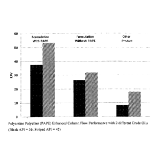
100901 Referring now to FIG. 5, the results of the tests are illustrated by
a chart showing the
flow performance of Mix no. 6, both with and without the polyamine polyether
(PAPE) for three
different -crude oils. The flow performance of the mixtures is represented by
the RockPerte
value (the "RPV") on. the Y-axis of the chart: The tests took into account the
time it takes for the
displacement of oil from the sand pack. This time is representative of the
time it takes for the
surfactant to migrate to the oil/water interface from the bulk aqueous phase.
21
100911 As shown by FIG. 5, the inclusion of the polyamine polyether in Mix
no. 6 improved
the RPV value (FIG. 5, W/PAPE) on multiple crude oils (FIG. 5, dark grey,
light grey, red
columns as compared to the same surfactant formulation without the polyamine
polyether (FIG.
5, No PAPE)) and the other demulsifying agent.
100921 Therefore, the present treatment additives and methods are well
adapted to attain the
ends and advantages mentioned, as well as those that are inherent therein. The
particular
examples disclosed above are illustrative only, as the present treatment
additives and methods
may be modified and practiced in different but equivalent manners apparent to
those skilled in
the art having the benefit of the teachings herein. Furthermore, no
limitations are intended to the
details of construction or design herein shown. It is therefore evident that
the particular
illustrative examples disclosed above may be altered or modified, and all such
variations are
considered within the scope and spirit of the present treatment additives and
methods. While
compositions and methods are described in terms of "comprising," "containing,"
"having," or
"including" various components or steps, the compositions and methods can
also, in some
examples, -consist essentially of' or -consist of' the various components and
steps. Whenever a
numerical range with a lower limit and an upper limit is disclosed, any number
and any included
range falling within the range are specifically disclosed. In particular,
every range of values (of
the form, "from about a to about b," or, equivalently, "from approximately a
to b," or,
equivalently, "from approximately a-b") disclosed herein is to be understood
to set forth every
number and range encompassed within the broader range of values. Also, the
terms have their
plain, ordinary meaning unless otherwise explicitly and clearly defined by the
patentee.
22
Date recue / Date received 2021-11-25