Note: Descriptions are shown in the official language in which they were submitted.
CA 03090873 2020-08-10
WO 2019/158554
PCT/EP2019/053492
1
DEVICE FOR INCREASING PERFORMANCE, COMFORT AND/OR
PREVENTING INJURY OF A USER OF A COMPUTER MOUSE
Technical field
The present disclosure relates to a wearable device for increasing
performance, comfort and/or preventing injury of a user of a computer mouse,
or the like. The device may be used as a gaming glove, i.e. a glove that is
intended for use in computer gaming, or as an ergonomic implement intended
for use by any computer operator.
Background
Many computer games are controlled at least partially by a computer
mouse. Especially in so-called first-person-shooter games, the mouse may be
used to control the aim of the player's weapon. Such control may require a
large range of movements, from minute ones to relatively large ones.
Moreover, such movements often need to be performed very quickly, leading
to a very high movement speed.
It is well known, that use of computer mice may lead to injuries, such
as carpal tunnel syndrome, and the like. Various devices have been produced
with the aim to reduce the risks associated with the use of computer mice.
U55925007A discloses a carpal cuff, which is designed to reduce the
risk of injuries on users of computer mice. Similar devices are disclosed in
U56082684A, W00236050A1 and W009059492A1.
There is a need for further improvements of these devices.
Summary
An object of the present disclosure is to provide an improved device for
reducing the risk of injury, as well as for improving the performance and/or
comfort, of computer mouse users.
The invention is defined by the appended independent claims, with
embodiments being set forth in the appended dependent claims, in the
following description and in the drawings.
CA 03090873 2020-08-10
WO 2019/158554
PCT/EP2019/053492
2
According to a first aspect, there is provided a device for increasing
performance, comfort and/or preventing injury of a user of a computer mouse
or the like. The device comprises a wrist support, having an upper side
adapted for receiving the user's wrist and/or lower forearm and an underside
adapted to bear against a planar surface, such as a table. The underside
presents a bearing arrangement for reducing friction against the planar
surface. The device further comprises a hand support, adapted for receiving a
part of the user's hand, wherein the hand support is horizontally +/- 40
degrees, preferably +/- 20 degrees or +/- 10 degrees, movable relative to the
wrist support.
The bearing arrangement for reducing friction against the planar
surface may be embodied as a roller bearing (e.g. ball transfer units) or as a
friction bearing, e.g. using one or more low friction polymer coated support
surface.
The device may generally be referred to as a "glove", which in the
present context implies a device that may be applied to the user's hand, wrist
and/or forearm.
The hand support may be movably connected to the wrist support.
In the device, movement between the hand support and the wrist
support may be limited.
The connection may comprise interacting surfaces on the hand support
and on the wrist support, at least one of the surfaces comprising a second
bearing arrangement, such as a ball bearing or a slide bearing.
The connection may comprise a rotatable connection by which the
hand support is rotatably connected to the wrist support, such that the hand
support and the wrist support are rotatable relative to each other about an
axis that provides an angle of less than 40 degrees, preferably less than 30
degrees or less than 15 degrees, relative to a vertical direction, when the
device is placed on a horizontal surface.
The hand support may be connected to the wrist support by a flexible
element, which may be fixedly connected or connectable to each of the hand
support and the wrist support.
CA 03090873 2020-08-10
WO 2019/158554
PCT/EP2019/053492
3
The flexible element may comprise a pair of attachment portions,
connectable to a respective one of the hand support and the wrist support
and a waist portion, whereby the attachment portions are movable relative to
each other through bending about the waist portion.
The flexible element may present less rigidity in a direction of said
bending about the waist portion than in a direction perpendicular thereto,
such
that the flexible element is easier to bend about an axis (A) that provides an
angle of less than 40 degrees, preferably less than 20 degrees or less than
degrees, relative to a vertical direction, than about an axis that is
10 horizontal.
A biasing element may be provided to bias the hand support and the
wrist support towards a predetermined relative position.
The hand support may be connected to the wrist support by means of
a joint which is provided at a position below the user's hand.
Alternatively, or as a supplement, the hand support is connected to the
wrist support by means of a joint which is provided at a position above the
user's hand.
A device as defined above provides improved performance with
respect to smaller sideways movements that the user carries out by merely
moving the hand, and not the wrist, relative to the planar surface.
Furthermore, as it reduces the resistance to be overcome when
making sideways movements by the hand and/or lower arm, the device
reduces the risk of injuries to the shoulder, arm and hand regions, or it
alleviates such injuries which have already arisen or begun to arise.
The bearing arrangement may comprise at least one ball bearing,
configured such that a spherical surface of the ball bearing protrudes from
the
underside such that it forms a lowermost portion of the wrist support.
The bearing arrangement may comprise a plurality of ball bearings,
positioned such that they define a two-dimensional support area.
Alternatively, or as a supplement, the bearing arrangement may
comprise a friction reducing surface, arranged on the underside of the wrist
support, and optionally also on an underside of the hand support. Such
CA 03090873 2020-08-10
WO 2019/158554
PCT/EP2019/053492
4
friction reducing surface may be provided so as to reduce friction against the
support on which the computer mouse is operated.
The rotatable connection may comprise a roller bearing.
The device may further comprise a wrist fastening device, for securing
the wrist and/or lower forearm to the wrist support.
The wrist fastening device may comprise one or more straps, a cuff or
a wristlet.
The device may further comprise a hand frame, connected to the hand
support, extending upwardly and/or forwardly and configured to at least
laterally interact with the hand.
The hand frame provides added leverage in transferring the hand's
movement to the hand support.
The device may further comprise a hand fastening device, for securing
the hand to the hand support.
The hand fastening device may comprise a glove, one or more straps,
a lacing arrangement, a cuff and/or a wristlet.
The wrist support may be sized to extend over at least 60 % of the user's
radius bone, preferably at least 70 %, at least 80 % or at least 90 %.
The device may further include a wrist positioning element, comprising
a support surface that is shaped so as to position a distal portion of the
user's
radius bone at a higher vertical level than a proximal portion of the user's
radius bone.
According to a second aspect, there is provided a kit of parts
comprising a device as describe dabove, and a sleeve, adapted for being
applied to a wrist or forearm of the user.
The sleeve may be a compression sleeve, adapted to provide a
compressive pressure of 15-60 mmHg on at least a portion of the user's wrist
or forearm.
The sleeve may be attached or attachable to the device.
According to a third aspect, there is provided a method of applying a
device for increasing performance, comfort and/or preventing injury of a user
of a computer mouse or the like. The method comprises providing a device as
described above, arranging a lower portion of a ventral side of the user's
wrist
CA 03090873 2020-08-10
WO 2019/158554
PCT/EP2019/053492
and/or lower forearm to bear against the upper side of the wrist support, and
arranging a portion of the user's hand comprising the carpus bones to bear
against an upper side of the hand support.
The method may further comprise attaching the user's wrist and/or
5 lower forearm to the wrist support by means of a wrist fastening device,
and
optionally attaching the user's hand to the hand support by means of a hand
fastening device.
The method may further comprise applying a compression sleeve to
the user's wrist or forearm prior to arranging the lower portion of the
ventral
side of the user's wrist to bear on the upper side of the wrist support.
According to a fourth aspect, there is provided use of a device as
described above, for computer gaming, preferably for a battle game, such as
a first-person shooter type game or a multiplayer online battle arena type
game.
Hence, the device is suitable for use in first-person shooter type
games, such as Counter-Strike: Global Offensive , since it reduces friction
against the support surface (such as a table) for long sideways movements.
Moreover, the device is suitable for online battle arena type games, such as
League of Legends , since it also allows for reduced friction when making
small sideways movements.
Brief description of the drawings
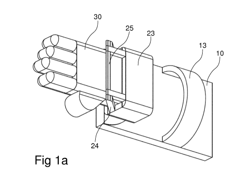
Fig la is a schematic perspective view of a gaming glove.
Fig lb is a schematic side view of the gaming glove in fig. la.
Fig 2a is a schematic top view of the gaming glove in fig. la.
Fig 2b-2d are schematic sectional views of the gaming glove in fig. 2a.
Fig. 3 schematically illustrates a first joint concept for providing a
rotatable joint between the wrist support and the hand support.
Fig. 4 schematically illustrates a second joint concept.
Figs 5a-5b schematically illustrates a third joint concept.
Fig. 6 schematically illustrates a fourth joint concept.
Fig. 7 schematically illustrates a fifth joint concept.
Fig. 8 schematically illustrates a sixth joint concept.
CA 03090873 2020-08-10
WO 2019/158554
PCT/EP2019/053492
6
Fig. 9 schematically illustrates an embodiment of a gaming glove worn
by a user, as seen from below.
Fig. 10 schematically illustrates an embodiment of a gaming glove
worn by a user, as seen from above.
Figs 11a-11b schematically illustrate an ergonomic support member,
which may be incorporated into the gaming glove.
Detailed description
Referring to the drawings, a gaming glove will according to the present
disclosure will now be described.
The gaming glove comprises a wrist support 10, which is formed by a
base member having at an underside 12 thereof, downwardly exposed
bearing members 121a, 121b, 121c, 121d, 121e and an upwardly exposed
face 11, which is adapted for receiving and supporting a part of a user's
forearm, typically the ventral side of the user's forearm.
The wrist support 10 may be formed as a relatively flat, longitudinal
member having a length of about 10-20 cm, preferably 15-20 cm, and a width
of about 5-10 cm, preferably 7-10 cm.
In other embodiments, the wrist support may be designed to extend
over at least 60 % of the user's radius bone, as seen along the user's arm,
preferably at least 70 %, at least 80 % or at least 90 %. In some
embodiments, the wrist support may extend through 100-120 % of the user's
radius bone. That is, the wrist support may also provide support for the
user's
elbow. The gaming glove may be provided in different sizes to fit differently
sized users.
The wrist support 10 may be formed of a polymeric material, such as
plastic or reinforced plastic. Alternatively, a relatively light metal, such
as
aluminum or titanium, may be used. In any event, it may be desirable to
select a material that provides minimum irritation to the user's skin. In
particular embodiments, the wrist support 10, and or the hand support, may
be formed of a thermoplastic polyurethane or by a thermoplastic elastomeric
material.
CA 03090873 2020-08-10
WO 2019/158554
PCT/EP2019/053492
7
An upper surface 11 of the wrist support may present a groove running
along the longitudinal direction and adapted to receive the user' forearm.
The upper surface 11 may be provided with a surface structure and/or
a material that promotes transfer of air around the user's arm. For example,
the surface may have protrusions and/or depressions, ridges, grooves, etc.,
which allow air to flow between the user's arm and the upper surface.
As an alternative, or supplement, the upper surface 11 may be
provided with a textile or fibrous material.
As yet another alternative, or supplement, the upper surface 11 may
present one or more padded areas, e.g. near edges of the upper surface.
As another option, at least 50 %, preferably 60 % or 80 % of the upper
surface 11 may be provided with padding to increase comfort.
Hence, the wrist support and/or the hand support may be padded, so
as to provide increased comfort. Examples of material include fabrics and
foamed polymer materials.
Moreover, the wrist support and/or the hand support may be formed
from at least two materials, including a first material that provides rigidity
and
a second, less rigid material that provides comfort. For example, the first
material may be a normal engineering plastic, whereas the second material
may be a rubber or TPE type material. The materials may be formed
separately and then bonded to each other, or they may be formed through a
co-injection molding process.
A wrist fastening device 13 may be provided, configured for attaching
the wrist support to the user's wrist, such that the wrist support will follow
movements of the user's wrist.
The wrist fastening device 13 may comprise one or more straps, which
may be resilient or non-resilient. The straps may be provided with an
attachment mechanism, such as a buckle, a hook-and-loop arrangement, or
the like, to allow the user to releasably and comfortably attach the wrist
support to the wrist. In the case where the strap(s) is/are resilient, no
attachment mechanism may be necessary.
A strap typically extends over less than 30 %, preferably less than 20
% or less than 10 %, of the length of the wrist support.
CA 03090873 2020-08-10
WO 2019/158554
PCT/EP2019/053492
8
As an alternative, a resilient cuff or wristlet may be provided, which
may extend over more than 30 %, preferably more than 50 % or more than 80
% of the length of the wrist support.
As yet another alternative, it is possible to use a lacing arrangement,
similar to a shoe-lacing arrangement, but preferably adapted so as to enable
it to be operated with one hand. An example of such an arrangement is
disclosed in US2004172853A.
A more general example may be where the free ends of the lacing
arrangements are twisted about a spool, followed by a locking action of the
spool and the lace ends. For example, the spool may be axially movable
between a first position, wherein it is rotatable for winding/unwinding the
lace
ends and a second position, wherein it is prevented from rotating. A bayonet
type locking mechanism may be provided for locking the spool in the second
position.
In embodiments using a sleeve or cuff, whether laced or otherwise
possible to tension around the user's arm, it is possible to arrange such
sleeve or cuff to be detachably attachable to the wrist support and optionally
the hand support. This may be rendered possible by attaching the sleeve or
cuff to the wrist/hand support by means of e.g. buttons, hook-and-look type
fasteners or the like.
This may be particularly advantageous in embodiments where the
sleeve or cuff extends over more than 30 % of a length of the user's radius
bone, such as 50-120%, preferably 50-100% of the length.
Needless to say, the sleeve or cuff may be fixedly attached to the wrist
support and optionally also to the hand support.
The underside 12 of the wrist support may present the bearing
members 121a, 121b, 121c, 121d, 121e. There may be 3-10, preferably 3-7
or 4-5 bearing members 121a, 121b, 121c, 121d, 121e, arranged to define a
two-dimensional support surface. For example, as illustrated, four bearings
121a, 121b, 121c, 121d may be arranged at corners of the wrist support, such
that they together define a rectangle, and one or more bearings 121e may be
arranged inside the rectangle, e.g. at or near its geometric center of
gravity.
CA 03090873 2020-08-10
WO 2019/158554
PCT/EP2019/053492
9
The bearing members 121a, 121b, 121c, 121d, 121e may be ball
transfer units, or similar, each comprising a housing and a load ball, and
optionally a plurality of support balls. The load ball may be made of a
metallic,
polymeric or ceramic material.
Alternatively, or as a supplement, the underside of the wrist support
may be provided with one or more low friction surfaces, e.g. surfaces coated
with a low-friction type polymer, such as PTFE. Such low friction surface may
extend over all or parts of the length of the wrist support and the hand
support.
At least one of the housings of the ball transfer units may be received
in recesses in the underside of the wrist support.
Alternatively, at least one of the housings may be arranged on the
outside of the underside of the wrist support.
As yet another option, at least one of the housings may be integrated
with the wrist support. For example, a recess in the underside of the wrist
support may directly receive the load ball and any support balls.
The gaming glove further comprises a hand support 20. The hand
support may be made of the same material as the wrist support 10.
The hand support 10 should be configured to provide support for the
carpus bones of the hand, while preferably not impeding movement of the
metacarpal bones.
Hence the hand support 10 may be entirely comprised within the two-
dimensional footprint provided by the wrist support 10.
Alternatively, the hand support 10 may extend slightly beyond the
footprint of the wrist support. Typically, such extent will be less than 20 %
of
the length of the wrist support, preferably less than 10 % or less than 5 %.
An upper surface 21 of the hand support may be approximately flush
with the upper surface 11 of the wrist support. To this end, the part of the
wrist support 10 where the hand support 20 is connected may be recessed,
so as to fit the hand support 20 and the bearing 26.
At least 50 %, preferably 60 % or 80 % of the upper surface 21 may be
provided with padding to increase comfort.
CA 03090873 2020-08-10
WO 2019/158554
PCT/EP2019/053492
The hand support 20 may be movable relative to an upwardly facing
surface of the wrist support 10. In particular, the hand support may be
movable relative to the wrist support along a plane that is horizontal +/- 40
degrees, preferably -F1- 20 degrees or -F1- 10 degrees.
5 Alternatively, an interface surface between the hand support and the
wrist support may be part spherical.
As one example, the hand support 20 may be rotatably connected to
the wrist support 10. The rotatable connection may be configured such that
the hand support and the wrist support are rotatable relative to each other
10 about an axis A that provides an angle of less than 40 degrees,
preferably
less than 30 degrees or less than 15 degrees, relative to a vertical
direction,
when the device is placed on a horizontal surface. Typically, the axis may be
substantially vertical.
The axis A may be situated within the two-dimensional footprint of the
wrist support, and preferably also within a two-dimensional footprint defined
by the bearings 121a, 121b, 121c, 121d on which the wrist support 10 rests
on the base, e.g. a table.
The rotational connection 26 may typically comprise a roller bearing,
one race of which being connected to the wrist support 10 and the other race
of which being connected to the hand support 20.
Alternatively, the hand support 20 may be slidable relative to the wrist
support 10. The underside 27 of the hand support and the upwardly oriented
bearing surface of the wrist support may be provided with a bearing
arrangement, such as a glide bearing or a roller bearing.
Moreover, one of the hand support 20 and the wrist support 10 may
comprise one or more guide members, which may interact with corresponding
guide members on the other one of the hand support 20 and the wrist support
10. For example, a guide member may comprise a pin or a fin and a
corresponding guide member may comprise a groove or a slot, which may be
curved.
The guide members may control the movement direction and limit the
movement, e.g. such that the hand support 20 may move and/or rotate
horizontally through a limited angle relative to the wrist support 10.
CA 03090873 2020-08-10
WO 2019/158554
PCT/EP2019/053492
11
Optionally, such guide members may also limit movement in the
vertical direction.
Guide members as described above may be combined with the
rotational connection 26 described above.
The hand support 20 may further comprise a frame 22, 23, 24, 25,
which is adapted to interact laterally with the user's hand, to make sure that
any sideways movement of the hand relative to the user's forearm results in a
rotation about the axis A.
As illustrated, the frame may comprise one, or a pair of, vertical
section(s) 22, extending upwardly from an upper surface of the hand support
20. The frame may further comprise one or two lateral sections 24, which may
extend forwardly of the vertical section 22, and optionally a transversal
section 25, which may extend between distal parts of the vertical sections 24
and/or between distal parts of the lateral sections 24.
The hand support 20 may further comprise a hand fastening device 30,
adapted to safely attach the user's hand to the hand support 20, such that the
hand support 20 will follow the user's hand movements.
The frame 22, 23, 24, 25 may be at least partially detachably
connected to the hand support 20. For example, the frame may, at one lateral
side thereof, be provided with a hinge and at the other lateral side thereof
with
a connector. Alternatively, the frame 22, 23, 24, 25 may be so flexible as to
render any hinge unnecessary.
As yet another alternative, the frame 22, 23, 24, 25 may be resilient
and flexible to such an extent that it returns to a closed position after
having
been opened, but does not need any connector.
The hand fastening device may comprise one or more of a cuff, a
wristlet, a strap or a glove. In the case of a glove, possibly a fingertip-
less
glove.
The hand fastening device 30 may be attached to the hand support
and/or to the frame 22, 23, 24, 25, if any. For example, a hand fastening
device in the form of a cuff, wristlet or glove may be attached both to the
hand
support 20 and to the frame 22, 23, 24, 25. It may be suitable to attach such
CA 03090873 2020-08-10
WO 2019/158554
PCT/EP2019/053492
12
hand support to distal parts of the lateral frame members 24, to distal parts
of
the vertical members 22 and/or to a cross member 23, 25.
The device may be used by arranging a lower portion of a ventral side
of the user's forearm to bear against the upper side 11 of the wrist support
and arranging a portion of the user's hand comprising the carpus bones to
bear against an upper side of the hand support.
Hence, in use, the lower part of the user's forearm rests against the
wrist support and the carpus bones of the user's hand rests against the hand
support.
The wrist support may be attached to the user's forearm by means of
the wrist fastening device 13.
The hand support may be attached to the user's hand by means of the
hand fastening device 30.
Hence, in use, the device may be securely attached to the user's arm
such that the wrist support's 10 downwardly exposed bearings reduce friction
against the supporting surface, which may be a table, optionally provide with
a mouse mat, thus allowing the device to follow the user's arm movements.
The hand support may be securely attached to the user's hand, such
that movements of the user's hand relative to the wrist are facilitated by the
bearing 26 forming the rotatable connection between the hand support 20 and
the wrist support 10.
The hand frame 22, 23, 24, 25 will abut, in particular, sides of the
user's hand to ensure that the user's hand movements are properly
transferred to the hand support.
Fig. 3 schematically illustrates a first joint concept for providing a
rotatable joint between the wrist support and the hand support. The joint may
comprise a pair of joint members 210, 220, which may be attached to, or
formed in one piece with, a respective one of the wrist support and the hand
support.
The joint members may be formed so as to partially overlap each
other. An area or overlap may be recessed in one or both of the joint
members, such that the joint members will take up less space in the direction
parallel with an axis of rotation of the joint. For example, the recesses 211,
CA 03090873 2020-08-10
WO 2019/158554
PCT/EP2019/053492
13
221 may be designed so that a total thickness of the joint members at the
area of overlap is about the same as that of the joint members outside the
area of overlap. The difference may preferably be less than 20%, less than
% or less than 5 % of the thickness of the area outside the area of overlap.
5 Moreover, one or more rotation guide portions 212, 213, 214; 222, 223,
224 may be provided. In the illustrated example, there is provided an outer
guide portion 212, 213; 222, 223 and a central guide portion 214; 224.
The central guide portion 214, 224 may be formed by a protrusion 214
in one of the recesses 211 and a depression or through hole 224 in the other
10 one of the recesses 221.
The outer guide portion may be formed by an arched portion 212, 222
of the transition between the recess 211, 221 and the non-overlapping portion
of the joint member. This arched portion may be formed so as to fit with a
distal portion 213, 223 of the other one of the joint members.
A joint lock (not shown) may be provided with a view to preventing the
joint members from separating in the direction along the axis of rotation.
Such
joint lock may be provided by e.g. a fastener attaching a washer to the
protrusion, the washer being larger than the corresponding recess of the
other joint member.
Fig. 4 schematically illustrates a second joint concept. This concept
resembles the one in fig. 3, but with one of the members 310 providing a slot
313 between a pair of edge portions 311, 312 and the other one (not shown)
providing a tongue that is to be received in the slot, together with a pin or
other joint lock (not shown) that may provide an axle about which the other
joint member (not shown) may rotate.
Fig. 6 illustrates a further design, wherein the arched portion 212 of
one of the joint members is further spaced from the distal portion 223 of the
other joint member, such that a gap is formed therebetween. This gap may
correspond to at least 1 %, preferably 5 %, 10 % or 15 %, of a length of the
overlap area as seen along the direction of the user's arm. The gap may
reduce friction.
Figs 5a-5b schematically illustrates a third joint concept. This concept
is based on a flexible member 535, which may be formed by a separate part
CA 03090873 2020-08-10
WO 2019/158554 PCT/EP2019/053492
14
that is attached to one or both of the hand support 351 and the wrist support
350, or which may be formed in one piece with one or both of the hand
support and the wrist support.
The flexible member 353 may comprise a pair of attachment portions
354, 355, which are separated by a waist portion 356. By designing the
member so that its thickness, at and near the waist portion is greater than
its
width at the waist portion, the member will be prone to bending about the
waist portion 356.
The waist portion 356 may be formed by a respective lateral space
357, 358 being provided to extend from an outer lateral edge of the member
and inwardly towards the waist portion 356. The lateral spaces 357, 358 may
be designed to define a respective central angle W about a bending axis, that
will limit the lateral bending of the member.
It is thus possible to control the amount of bending that is to be allowed
through the size of the lateral space. Notably, it is possible to provide
symmetric or asymmetric bending properties.
With a flexible member, it is possible to provide a bias towards a
predetermined relative position of the hand support and the wrist support, in
that the flexible member may be elastically flexible, so as to be prone to
returning to its original, unloaded position.
The flexible member may be formed of an elastomeric material, which
may be foamed. Examples of materials include rubber materials,
polyurethane and thermoplastic elastomers.
The flexible member may be releasably attachable to the joint
members, such that it is possible to exchange it, e.g. in order to change the
angle limitations and/or to change the stiffness of the joint.
Fig. 7 and fig. 8 illustrate embodiments wherein such a biased effect
can be provided by means of a spring member 360. The spring member 360
may be combined with the articulated joint designs according to figs 3, 4 and
6. Moreover, the spring member 360 may be used together with the flexible
and optionally elastic member 353 of figs 5a-5b, as illustrated in fig. 8.
The spring member 360 may be releasably attached, such that it is
possible to change it in order to provide a desired stiffness of the joint.
CA 03090873 2020-08-10
WO 2019/158554 PCT/EP2019/053492
Finally, and as illustrated in fig. 7, it is possible to base the entire joint
on the spring member 360. That is, the spring member may be the device
which holds the joint members together. Optionally, an area of overlap
between the joint members may be used to limit the bending motion to a
5 single plane.
Fig. 9 schematically illustrates an embodiment of a gaming glove worn
by a user, as seen from below. In this figure, the wrist support and the hand
support are illustrated, as is the joint. While in the illustrated version,
the joint
is based on figs 5a-5b, it is understood that any one of the joint designs
10 provided herein may be used.
Moreover, in fig. 9, there is illustrated the bearing arrangements 3501,
3511 which are provided on the wrist support 350 and on the hand support
351, as well as the sleeves 3502, 3512 and straps 3513 that are used to
attach the glove to the user's lower arm, to his hand and to his fingers. It
is
15 noted that in the embodiment illustrated in fig. 9, the joint is
provided on the
underside of the device, i.e. below the user's arm and closer to the support
surface on which the computer mouse is operated.
Fig. 10 schematically illustrates an embodiment of a gaming glove
worn by a user, as seen from above. In this embodiment, the joint 353 is
arranged on the upper part of the glove, i.e. on the upper side of the user's
hand 502 and wrist 501. The joint may be designed just like in fig. 9.
Figs 11a-11b schematically illustrate an ergonomic support member
600, which may be incorporated into the gaming glove. This ergonomic
support member is designed to insure that the distal part of the user's radius
bone is spaced further from the support surface than it would normally be,
such that a desired angle of the user's wrist can be effortlessly maintained.
The support member may comprise a first support surface 601 that is
straight or slightly curved in the longitudinal direction of the user's arm
and
concave as seen in a transversal direction. This first support surface may be
intended to support part of the user's lower arm 501. The support member
may comprise a summit portion 603, which is concave also in the longitudinal
direction, where the user's wrist joint 503 is to be positioned. Finally, the
support member may comprise a second support surface 602, that is
CA 03090873 2020-08-10
WO 2019/158554
PCT/EP2019/053492
16
intended to support the proximal portion of the user's hand 502. When placed
on a horizontal surface, the second support surface may present a greater
slope than the first support surface, as seen along the longitudinal direction
of
the user's arm.
The support member 600 may be integrated, such as attached to or
formed in one piece with, the wrist support.
The support member 600 may present one or more through holes or
openings, such that it will allow air flow to/from the user's arm.
While the device may be used with any type of computer mouse and
with any type of program, one specifically suitable use case is for first-
person-
shooter type games, such as Counter-Strike: Global Offensive . In such use,
a mouse sensitivity may typically be set to less than about 1000 DPI (dots per
inch). In such use, the wrist support will be essential in providing friction
reduction for large sideways movements of the mouse.
Another specifically suitable use case is for the multiplayer online battle
arena type games, such as League Of Legends . In such use, a mouse
sensitivity may typically be set to more than about 2000 DPI (dots per inch).
In such use, the hand support will be essential in providing friction
reduction
for small sideways movements of the mouse.
It may be desirable to provide one or more joint covers. For example,
referring to fig. 9, it may be desirable to provide a joint cover on the
underside
of the joint, to provide a smooth transition between the wrist support 350 and
the hand support 351. Such a support may be formed by extending the hand
support and the wrist support such that they provide a rotary joint with
closely
spaced arched edges like illustrated in fig. 4, as opposed to the open joint
illustrated in fig. 9. Alternatively, a portion of the hand support and/or of
the
wrist support may extend below the joint, and optionally overlap the other one
of the hand support and/or the wrist support.
For example, it may be desirable to provide a downwardly facing
support which extends all the way from the hand support through the wrist
support to provide a substantially continuous downwardly facing support
surface. Such downwardly facing support surface may thus be continuous as
a consequence of an overlap, or it may be articulated.
CA 03090873 2020-08-10
WO 2019/158554
PCT/EP2019/053492
17
It may also be desirable to provide padding on the side of the joint that
faces the user's wrist joint.
In a further embodiment, the gaming glove may comprise a sleeve that
is adapted to provide a compression effect on the user's wrist and/or forearm.
In particular, such sleeve may be adapted to provide a compression on
the order of 15-60 mmHG. In various embodiments, the sleeve may be
designed to provide a pressures in the following ranges: 20-30 mmHg, 30-40
mmHg, 40-50 mmHg or 50-60 mmHg. In yet further embodiments, the sleeve
may be designed to provide pressures in the following ranges: 15-21 mmHg,
23-32 mmHg or 34-46 mmHg.
The sleeve may be provided as a closed sleeve that is pulled onto the
user's arm like a sock. Alternatively, the sleeve may be at least partially
open,
along its length, such that it can be closed by e.g. a zipper, hook-and-loop
type fastener or the like.
The sleeve may separate from the remainder of the gaming glove,
such that the sleeve is applied to the user's wrist or forearm prior to
applying
the glove. Alternatively, the sleeve may be attached to or attachable to, the
gaming glove.
The sleeve present a length and shape sufficient for it to extend from
above the user's elbow, along the forearm and over part of the user's hand. In
particular, the sleeve may present a loop, strap or hole adapted for receiving
at least one of the user's fingers, for example the user's thumb.
Moreover, at the portion of the gaming glove overlapping the user's
hand, it may be desirable to leave the underside of the hand uncovered, such
that direct skin contact with the computer mouse is achieved.
Such longer sleeves may be particularly preferred in conjunction with a
wrist support designed to extend over at least 60 (:)/0 of the user's radius
bone,
as seen along the user's arm, preferably at least 70 %, at least 80 (:)/0 or
at
least 90 %. In some embodiments, the wrist support may extend through 100-
120% of the user's radius bone.
Where a separate sleeve is used, the wrist fastening device and the
hand fastening device may operate as described above.
CA 03090873 2020-08-10
WO 2019/158554
PCT/EP2019/053492
18
As yet another feature, it may be possible to provide an illumination
device in or on the gaming glove. For example, an illumination device may be
provided to illuminate the base on which the gaming glove/mouse are
operated. Such illumination device may comprise a power source, such as a
battery, one or more light sources, such as LEDs and optionally one or more
light guides. A controller may also be provided, e.g. to turn the illumination
on/off and optionally also to change color of the illumination, should the
light
sources be provided in the form of e.g. RGB enable light sources. The
controller may communicate with e.g. a computer, a computer peripheral or a
smartphone/tablet. Such communication may be wireless. Thus a user
interface may be provided via an app in the smartphone/tablet or in the
computer.