Note: Descriptions are shown in the official language in which they were submitted.
ADJUSTABLE PLIERS
Technical Field of the Invention
The present invention relates generally to pliers. More particularly, the
present invention
relates to adjustable pliers having increased contact surface area between the
jaws of the pliers
and a work piece.
Background of the Invention
Pliers are a common hand tool used to rotate work pieces. Many different types
of pliers
exist, including locking pliers, needle nose pliers, and adjustable pliers. As
shown in FIG. 10, a
conventional adjustable pliers 1000 include a first handle 1005 and a second
handle 1010
pivotally movable relative to each other. The first handle 1005 leads to a
first jaw 1015 and the
second handle 1010 leads to a second jaw 1020, wherein the first and second
jaws 1015, 1020
cooperatively form a jaw gripping area that is adapted to grip a work piece.
The second handle
1010 includes a slot 1025 through which a pin 1030 can be inserted to allow
the first handle 1005
to pivot about the second handle 1010.
As shown, conventional adjustable pliers 1000 grip work pieces with teeth
located on the
first and second jaws 1015, 1020 of the pliers. This provides two gripping
surfaces between the
pliers and the work piece and a contact surface area equal to, at most, the
area of the teeth on the
first and second jaws 1015, 1020. Compressive gripping forces from the pliers
1000 is
transmitted to the work piece through the contact area between the pliers and
work piece. For
this reason, additional contact surface area between the pliers and the work
piece would be
advantageous to more efficiently apply compressive gripping forces from the
pliers to the work
1
Date Recue/Date Received 2020-11-26
piece. This additional contact surface area subsequently minimizes wear on
fasteners as well as
reduces wear on the plier gripping areas.
Summary of the Invention
The present invention broadly comprises pliers with enhanced contact surface
area
.. between the pliers jaw and a work piece. For example, the tool can include
receiving surfaces
defined within the handles of the tool to increase the number of surfaces that
are adapted to
contact the work piece and therefore increase the contact surface area between
the pliers and the
work piece to maximize the pliers' grip on the work piece.
For example, the present invention broadly comprises pliers for applying
compressive
gripping forces to a work piece having a work piece shape, for example, and
without limitation, a
hex head bolt. The pliers include a first handle, a first jaw extending from
the first handle and
having first jaw teeth, a second handle pivotally coupled to the first handle,
a second jaw
extending from the second handle and having second jaw teeth, a pin pivotably
coupling the first
and second handles at an adjustment slot, wherein the pin is adapted to be
selectively movable
within the slot to adjust a gap distance between the first and second jaws, a
first receiving surface
defined within the first handle and extending at a first angle relative to the
first jaw teeth, and a
second receiving surface defined within the second handle and extending at a
second angle
relative to the second jaw teeth. The first and second receiving surfaces and
first and second jaw
teeth, cooperatively defines a shape that substantially corresponds to the
exterior shape of a work
piece, and at least a portion of the first receiving surface, second receiving
surface, first jaw
teeth, and second jaw teeth contact the work piece during use to maximize grip
of the pliers
against the work piece.
2
Date Recue/Date Received 2020-11-26
The present invention also broadly comprises pliers for applying compressive
gripping
forces to a work piece with a work piece shape. The pliers include first and
second handles
respectively extending to first and second jaws respectively having first and
second teeth
substantially parallel to one another, the second handle including a slot
disposed therein. The
.. pliers can further include a pin extending through the slot and dimensioned
to be selectively
movable within the slot to adjust a gap between the first and second jaws, a
first receiving
surface defined within the first handle, the first receiving surface extending
at a first angle to the
first jaw teeth, and a second receiving surface defined within the second
handle, the second
receiving surface extending at a second angle to the second jaw teeth. The
first and second
.. receiving surfaces and the first and second jaw cooperatively define a
shape that corresponds to
the exterior shape of the work piece, and wherein at least a portion of the
first and second
receiving surfaces and first and second jaw teeth are adapted to contact the
exterior surface of the
work piece during use.
Brief Description of the Drawings
For the purpose of facilitating an understanding of the subject matter sought
to be
protected, there are illustrated in the accompanying drawings embodiments
thereof, from an
inspection of which, when considered in connection with the following
description, the subject
matter sought to be protected, its construction and operation, and many of its
advantages should
be readily understood and appreciated.
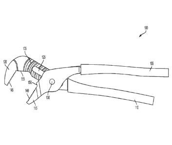
FIG. 1 is a side view of pliers according to an embodiment of the present
invention.
FIG. 2 is a side view of pliers with an example smaller work piece gripped by
the jaws
according to an embodiment of the present invention.
3
Date Recue/Date Received 2020-11-26
FIG. 3 is a side view of pliers with an example larger work piece gripped by
the jaws
according to an embodiment of the present invention.
FIG. 4 is an enlarged partial side view of pliers gripping an example smaller
hexagonal
work piece according to an embodiment of the present invention.
FIG. 5 is an enlarged partial side view of pliers gripping an example larger
hexagonal
work piece according to an embodiment of the present invention.
FIG. 6 is an enlarged partial side view of pliers gripping an example square
work piece
according to an embodiment of the present invention.
FIG. 7 is an enlarged partial side view of pliers gripping an example
rectangular work
piece according to an embodiment of the present invention.
FIG. 8 is an enlarged partial side view of pliers gripping an example circular
work piece
according to an embodiment of the present invention.
FIG. 9 is an enlarged partial sectional view of an adjustment mechanism
according to an
embodiment of the present invention.
FIG. 10 is a side view of a prior art pliers.
Detailed Description of the Embodiments
While this invention is susceptible of embodiments in many different forms,
there is
shown in the drawings, and will herein be described in detail, a preferred
embodiment of the
invention with the understanding that the present disclosure is to be
considered as an
exemplification of the principles of the invention and is not intended to
limit the broad aspect of
the invention to embodiments illustrated. As used herein, the term "present
invention" is not
intended to limit the scope of the claimed invention and is instead a term
used to discuss
exemplary embodiments of the invention for explanatory purposes only.
4
Date Recue/Date Received 2020-11-26
The present invention broadly comprises pliers with receiving surfaces formed
in the
handles of the pliers that are cooperatively adapted to increase the contact
surface area between
the pliers and a work piece. The receiving surfaces can cooperatively grip the
work piece with
increased contact surface area between the pliers and work piece, compared to
conventional
pliers that are adapted to only contact the work piece at the jaws.
Referring to FIGs. 1-3, a tool 100 can include a first handle 105 and a second
handle 110
coupled together in a pivotal manner. The first handle 105 can lead to a first
jaw 115 and the
second handle 110 can lead to a second jaw 120. The second handle 110 can have
a slot 125
disposed therein that is adapted to receive a pivot pin 130 coupled to the
first handle 105 and
allow a pivotal movement between the first handle 105 and second handle 110.
The first 105 and
second 110 handles can be further coupled together with an adjustment
mechanism 135 that
resists pivotal movement of the first handle 105 about the second handle 110
when engaged. The
adjustment mechanism 135 can include offset teeth of both first and second
handles 105, 110
meshingly engaging one another, as described below in more detail.
The head of the tool 100 can have various components that are adapted to grip
a work
piece during use to apply compressive gripping forces to the work piece. For
example, the first
jaw 115 can include first teeth 140 and the second jaw 120 can include second
teeth 145 that are
adapted to grip the work piece in a conventional manner. However, the first
handle 105 can also
include a first receiving surface 150 formed within the first handle 105 and
that provides an
additional contact surface for gripping the work piece and applying
compressive gripping forces
to the work piece. Similarly, the second handle 110 can include a second
receiving surface 155
that can grip the work piece during use. By providing additional contact
surfaces, the tool 100
5
Date Recue/Date Received 2020-11-26
can contact the work piece with more surface area and more efficiently apply
compressive
gripping force from the tool 100 to the work piece.
The first receiving surface 150 can be angled at about 60 degree angle
relative to the teeth
140 of the first jaw 115 and, similarly, the second receiving surface 155 can
be angled at an
.. angle of about 60 degrees relative to the teeth 145 of the second jaw 120.
In this manner, and as
shown in FIGs. 2 and 3, the teeth 140, 145 and receiving surfaces 150, 155 can
cooperatively
grip, for example, a hexagonally shaped work piece W, such as, for example, a
hex head bolt or
nut, with additional surface area and therefore with improved efficiency,
compared to
conventional pliers, which only grip the work piece W with the teeth 140, 145.
For example, the
.. same tool 100 can grip a smaller hexagonal work piece W, as shown in FIGs.
2 and 4; and also
grip a larger hexagonal work piece W, as shown in FIGs. 3 and 5.
The tool 100 can further grip square or rectangular work pieces in an improved
manner,
as shown in FIGs. 6 and 7, respectively. For example, as shown in FIG. 6, the
teeth 140, 145 of
the jaws 115, 120 directly contact the work piece W during use. However, the
tool 100 can
.. include a first corner 156 intersecting the first teeth 140 and the first
receiving surface 150, and a
second corner 157 intersecting the second teeth 145 and the second receiving
surface 155. These
corners 156, 157 provide additional contact areas with the work piece W during
the application
of compressive gripping forces. In particular, the corners 156, 157 also
contact the work piece W
and reduce the chances of the work piece W slipping about the teeth 140, 145,
which a rotational
force is applied to the tool.
Referring to FIG. 8, the tool 100 can also be advantageously be used on
circular shaped
work pieces W. For example, and as shown, the tool 100 can grip circular
shaped work piece W
with the teeth 140, 145, as with conventional pliers. The tool 100 can also
contact the circular
6
Date Recue/Date Received 2020-11-26
work piece W at the receiving surfaces 150, 155, despite the receiving
surfaces 150, 155 not
forming a shape entirely complementary to the circular shape of the work piece
W. As shown,
the receiving surfaces 150, 155 can be tangent to the work piece W and grip
the work piece W at
the contact points between the receiving surfaces 150, 155 and work piece W.
FIG. 9 illustrates an adjustment mechanism 135 according to an embodiment of
the
present invention. As shown, the adjustment mechanism 135 can include first
adjustment teeth
160 associated with the first handle 105, and second adjustment teeth 165
associated with the
second handle 110. The adjustment teeth 160, 165 can be generally parallel to
one another and
can meshingly engage the first handle 105 with the second handle 110 for
releasable coupling of
the first 105 and second 110 handles. The adjustment teeth 160, 165 can
further be angled
relative to a handle direction in which the first 105 and second 110 handles
extend. For example,
the first adjustment teeth can have first leading faces 167 and first trailing
faces 169, and the
second adjustment teeth 165 can have second leading faces 171 and second
trailing faces 173.
The first leading face 167 and the second trailing face 173 can extend at a
non-normal angle to a
handle direction about which the first 105 and second 110 handles extend. For
example, the first
leading face 167 and the second trailing face 173 can extend at an angle that
is about 8.5 degrees
to an angle normal to the handle direction. Similarly, the first trailing face
169 and the second
leading face 171 can extend at an angle that is about 25 degrees to an angle
normal to the handle
direction. With this undercut, the adjustment mechanism 135 has been found to
form a better
grip between the first 105 and second 110 handles, compared to other angular
orientations of
conventional adjustment teeth.
As used herein, the term "coupled" and its functional equivalents are not
intended to
necessarily be limited to direct, mechanical coupling of two or more
components. Instead, the
7
Date Recue/Date Received 2020-11-26
term "coupled" and its functional equivalents are intended to mean any direct
or indirect
mechanical, electrical, or chemical connection between two or more objects,
features, work
pieces, and/or environmental matter. "Coupled" is also intended to mean, in
some examples, one
object being integral with another object.
The matter set forth in the foregoing description and accompanying drawings is
offered
by way of illustration only and not as a limitation. While particular
embodiments have been
shown and described, it will be apparent to those skilled in the art that
changes and modifications
may be made without departing from the broader aspects of the inventors'
contribution. The
actual scope of the protection sought is intended to be defined in the
following claims when
.. viewed in their proper perspective based on the prior art.
8
Date Recue/Date Received 2020-11-26