Note: Descriptions are shown in the official language in which they were submitted.
COLLAPSIBLE HANDLE FOR A TOOL
[0001] This paragraph intentionally left blank.
BACKGROUND
[0002] The present invention generally relates to tools having long
handles, such as
without limitation implements such as brooms, mops, or others as some
examples.
[0003] Conventional push brooms, dust brooms, mops, and other
household cleaning or
other implements have long handles that typically end in a threaded cap that
can be screwed
into a mop head or brush head having an internally threaded hole for receiving
the handle. The
purpose of the handle is to enable the user to use the implement comfortably,
but at the same
time, the handle causes the implement to take up a lot of space.
[0004] The problem associated with the length of conventional handles
manifests itself
in various ways. The shipping of brooms from the manufacturer or distribution
center to a
retail store where they will be sold, or to a purchaser is cumbersome and
unduly expensive in
comparison to the value of the item because the implements take up so much
shipping space
and are awkward to stack or otherwise bundle conveniently for shipment.
Likewise,
implements with long handles are difficult to store in small spaces such as
janitorial closets, the
work vehicles of tradesmen and tradeswomen, or in other places. Long
conventional handles
also present problems in terms of placement on store shelves where space is
well-known to be
at a premium.
[0005] Handles that slide into one another, or "telescope," have been
used to provide
collapsibility for some implements, but they are not ideally suited for the
application of axial
forces such that which occurs when using a broom, mop, or other tool or
implement. Such
telescope handles generally tend to break prematurely or collapse unexpectedly
when in use.
Moreover, these types of handles require some sections to have a smaller
diameter than others,
which unacceptably reduces strength and rigidity. Another problem with
telescoping handles is
that foreign particles or liquids can find their way into the telescoping
portions and can
interfere with proper operation to collapse or extend the handle. Still
another problem is that
the internal mechanism that permits the telescoping action can break, which
renders the handle
to about half the size it needs to be for comfortable operation.
1
Date Recue/Date Received 2022-02-15
CA 03091432 2020-08-17
WO 2019/161379 PCT/US2019/018555
[0006] Although some cleaning implements are shipped for convenience with
separate
handle segments that must be assembly by the end user, such constructions
cannot readily be
broken back down easily or conveniently once assembled and therefore do not
offer a usable
solution.
[0007] What is needed is an implement that has an elongated handle that can
easily be
broken down for storage or shipment so that it takes up much less space,
maintain a mechanical
coupling between segments of the handle when collapsed, and still be very
sturdy and
dependable.
SUMMARY OF THE INVENTION
[0008] A tool with foldable tool handle according to the present disclosure
provides a
hinge mechanism comprising a double-jointed articulating hinged joint. The
hinge mechanism
generally comprises four active hinge components in one embodiment, which are
configured to
cooperate for creating a rigid and torque resistant coupling between pivotably
connected first
and second handle sections or members. The use of multiple springs or
fasteners is not
required, thereby providing a mechanical simple and reliable constructions
without need for
use of multiple springs or fasteners. The handle is changeable via operation
of a toggle linkage
which couples first and second handle members together between (i) an unfolded
condition in
which first and second handle members pivotably coupled together by the hinged
joint are
coaxially aligned with a longitudinal axis of the handle, and (ii) a folded
condition in which the
second handle member movable to a position laterally offset from the
longitudinal axis in side-
by-side relationship to the first handle member for compactly shipping or
storing the tool. In
some non-limiting embodiments, the tool may be a maintenance tool such as
broom or mop.
Other type tools may use the articulating joint.
[0009] The hinge mechanism includes a multitude of different locking
features and
actions which collectively form a mechanically interlocked joint when the
first handle member
is coaxially aligned and coupled to the second handle member with the handle
assembly in the
straight operational unfolded configuration or condition. The multiple locking
feature act in
concert to form an axially rigid handle assembly which resists twisting and
torsional forces
acting about the joint around the longitudinal axis when the tool is in use.
Such robust joints
thus have many practical uses and applications, only one of which is described
herein as an
example.
2
CA 03091432 2020-08-17
WO 2019/161379 PCT/US2019/018555
[00010] In one aspect, a foldable elongated tool handle for compact storage
of a tool
comprises: a longitudinal axis; an elongated first handle member comprising a
terminal end
configured for coupling to a tool, and a coupling end; an elongated second
handle member
comprising a coupling end; the coupling ends of the first and second handle
members hingedly
coupled together at a first articulated joint via an elongated toggle linkage;
the toggle linkage
having a rigid body comprising a first arm portion opposite a second arm
portion, and a central
middle portion therebetween; the first arm portion of the toggle linkage
slideably insertable
into a first central axial passage in the coupling end of the first hinge
member, and the second
arm portion of the toggle slideably insertable into a second central axial
passage in the coupling
end of the second handle member; the handle changeable via operation of the
toggle linkage
between (i) an unfolded condition in which the first and second handle members
are coaxially
aligned with the longitudinal axis. and (ii) a folded condition in which the
second handle
member is laterally offset from the longitudinal axis in side-by-side
relationship to the first
handle member.
[00011] In another aspect, a foldable tool handle with articulating joint
comprises: a
longitudinal axis; an elongated first handle member comprising first and
second ends; an
elongated second handle member comprising first and second ends; the first
handle member
hingedly coupled to the second handle member by a double-jointed articulating
joint; the
articulating joint comprising a first coupler fitting attached to the first
end of the first handle
section, a second coupler fitting attached to the first end of the second
handle section, and a
toggle linkage; the toggle linkage comprising an elongated body including a
first arm portion
opposite a second arm portion, and a central middle portion located
therebetween; the toggle
linkage pivotably coupled to: (i) the first coupler fitting via a first pivot
pin slideably received
in an elongated slot of the first arm portion, and (ii) the second coupler
fitting via second pivot
pin slideably received in an elongated slot of the second arm portion; the
handle changeable via
operation of the toggle linkage between (i) an unfolded condition in which the
first and second
handle members are coaxially aligned with the longitudinal axis, and (ii) a
folded condition in
which the second handle member is laterally offset from the longitudinal axis
in side-by-side
relationship to the first handle member via sliding the pivot pins in their
respective slots.
[00012] In another aspect, a method for operating a tool having a foldable
elongated tool
handle comprises: providing a tool handle comprising an elongated first handle
member in a
3
CA 03091432 2020-08-17
WO 2019/161379 PCT/US2019/018555
folded configuration axially offset from a second handle member, the handle
members
hingedly coupled together at their respective coupling ends by a toggle
linkage, the toggle
linkage pivotably coupled to the first handle member via a first pivot pin,
and the toggle
linkage pivotably coupled to the second handle member via a second pivot pin
forming a
double-jointed articulating joint; rotating the first handle member about the
joint into coaxial
alignment to the second handle member; inserting a first aim portion of the
toggle linkage into
a first axial passage of the coupling end of the first hinge member, the first
arm portion having
a rectilinear cross-sectional shape which locking engages a complementary
configured cross-
sectional shape of the first axial passage; inserting a second arm portion of
the toggle linkage
into a second axial passage of the coupling end of the second hinge member,
the second arm
portion having a rectilinear cross-sectional shape which locking engages a
complementary
configured cross-sectional shape of the second axial passage; and inserting a
first plurality of
axial protrusions at the coupling end of the first handle member between a
second plurality of
axial protrusion at the coupling end of the second handle member to form an
interlocked
arrangement; wherein the first handle member coupled to the second handle
member in coaxial
alignment defines an unfolded configuration.
BRIEF DESCRIPTION OF THE DRAWINGS
[00013] The features of the exemplary embodiments will be described with
reference to
the following drawings where like elements are labeled similarly, and in
which:
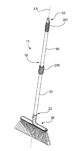
[00014] FIG. 1 is a perspective view of a long-handled tool comprising a
collapsible tool
handle shown in an axially straight unfolded operational configuration or
condition,
constructed in accordance with an embodiment of the present invention.
[00015] FIG. 2 is a perspective side view thereof showing only the handle;
[00016] FIG. 3 is a side view thereof showing the handle from a different
angle,
[00017] FIG. 4 is a perspective view showing the tool handle in a folded
storage
configuration or condition;
[00018] FIG. 5 is a cross-sectional side view of the tool;
[00019] FIG. 6 is an enlarged cross-sectional detail of the hinged joint
taken from FIG.
5;
[00020] FIG. 7 is enlarged perspective view of the hinged joint showing the
collapsible
handle in the folded configuration or condition;
4
CA 03091432 2020-08-17
WO 2019/161379 PCT/US2019/018555
[00021] FIG. 8 is an exploded view thereof;
[00022] FIG. 9 is a first side view of the hinged joint in an axially
coupled position;
[00023] FIG. 10 is a second side view thereof from a different angle 90
degrees from the
view shown in FIG. 9;
[00024] FIG. 11 is the side view of FIG. 9 showing the hinged joint in a
partially open
position;
[00025] FIG. 12 shows the too handle in the unfolded and axially straight
configuration
or condition;
[00026] FIG. 13 shows the tool handle in the folded configuration or
condition in which
a first handle section is laterally offset and parallel to a first handle
section coupled to an
implement of the tool;
[00027] FIG. 14 is an enlarged view of the implement coupled to the handle;
[00028] FIG. 15 is a side cross-sectional view of the tool handle in a
first folded
position;
[00029] FIG. 16 is a perspective view thereof;
[00030] FIG. 17 is a side cross-sectional view of the tool handle in a
second position;
[00031] FIG. 18 is a perspective view thereof;
[00032] FIG. 19 is a perspective view of the tool handle in a third
position;
[00033] FIG. 20 is a side cross-sectional view thereof;
[00034] FIG. 21 is a perspective view of the tool handle in a fourth
position;
[00035] FIG. 22 is a side cross-sectional view thereof;
[00036] FIG. 23 is a perspective view of the tool handle in a fifth
position;
[00037] FIG. 24 is a side cross-sectional view thereof;
[00038] FIG. 25 is a first perspective view of the upper coupler fitting of
the tool handle
of FIG. 1;
[00039] FIG. 26 is a second perspective view thereof;
[00040] FIG. 27 is first side view thereof;
[00041] FIG. 28 is a second side view thereof;
[00042] FIG. 29 is a third side view thereof;
[00043] FIG. 30 is a fourth side view thereof;
[00044] FIG. 31 is a bottom view thereof;
CA 03091432 2020-08-17
WO 2019/161379 PCT/US2019/018555
[00045] FIG. 32 is a top view thereof;
[00046] FIG. 33 is a first perspective view of the lower coupler fitting of
the tool handle
of FIG. 1;
[00047] FIG. 34 is a second perspective view thereof;
[00048] FIG. 35 is first side view thereof;
[00049] FIG. 36 is a second side view thereof;
[00050] FIG. 37 is a third side view thereof;
[00051] FIG. 38 is a fourth side view thereof;
[00052] FIG. 39 is a bottom view thereof;
[00053] FIG. 40 is a top view thereof;
[00054] FIG. 41 is a perspective view of the toggle linkage of the tool
handle of FIG. 1;
[00055] FIG. 42 is front view thereof;
[00056] FIG. 43 is a side view thereof; and
[00057] FIG. 44 is a top view thereof.
[00058] All drawings are schematic and not necessarily to scale. Parts
shown and/or
given a reference numerical designation in one figure may be considered to be
the same parts
where they appear in other figures without a numerical designation for brevity
unless
specifically labeled with a different part number and described herein.
DETAILED DESCRIPTION OF EMBODIMENTS
[00059] The features and benefits of the invention are illustrated and
described herein by
reference to preferred but non-limiting exemplary ("example") embodiments.
This description
of the embodiments is intended to be read in connection with the accompanying
drawings,
which are to be considered part of the entire written description.
Accordingly, the invention
expressly should not be limited to such embodiments illustrating some possible
non-limiting
combination of features that may exist alone or in other combinations of
features; the scope of
the invention being defined by the claims appended hereto.
[00060] In the following description, for purposes of explanation, numerous
specific
details are set forth in order to provide a thorough understanding of example
embodiments. It
will be evident to one skilled in the art, however, that embodiments can be
practiced without
these specific details, or with various combinations of these details.
6
CA 03091432 2020-08-17
WO 2019/161379 PCT/US2019/018555
[00061] In the description of embodiments disclosed herein, any reference
to direction or
orientation is merely intended for convenience of description and is not
intended in any way to
limit the scope of the present invention. Relative terms such as "lower,"
"upper," "horizontal,"
"vertical," "above," "below," "up," "down," "top" and "bottom" as well as
derivative thereof
(e.g., "horizontally," "downwardly," "upwardly," etc.) should be construed to
refer to the
orientation as then described or as shown in the drawing under discussion.
These relative terms
are for convenience of description only and do not require that the apparatus
be constructed or
operated in a particular orientation. Terms such as "attached," "affixed," -
connected,"
"coupled," "interconnected," and similar refer to a relationship wherein
structures may be
secured or attached to one another either directly or indirectly through
intervening structures, as
well as both movable or rigid attachments or relationships, unless expressly
described
otherwise.
[00062] With initial reference to FIGS. 1-14, one non-limiting embodiment
of a long-
handed tool 11 with collapsible handle according to the present disclosure is
illustrated for
creating a compact tool configuration for shipment, storage, packaging, and/or
display. Tool
11 includes a collapsible and jointed elongated handle assembly 10 (or
variously "handle" 10
for brevity) defining a proximal end 52 closest to a user, a distal end 22,
and longitudinal axis
LA extending therebetween. Distal end 22 is configured for mounting an
implement 30
thereto, such as broom or other implement as further described herein. Distal
end 22 of the
tool handle 10 may rigidly coupled to implement 30 as shown, or alternatively
rotatably/pivotably coupled to the implement in other embodiments.
[00063] The collapsible handle 10 includes elongated lower handle member 20
and
elongated upper handle member 50 pivotably and hingedly coupled together by a
hinge
mechanism 60 comprising an articulated joint 61. In one embodiment, the hinge
mechanism
60 is configured so that the upper handle member 50 is rotatable at least 180
degrees relative to
the lower handle member 20 to place the handle 10 in a collapsed folded
configuration for
shipment, storage, packaging, and/or display. This rotation is illustrated by
a comparison for
example of FIGS. 12 and 13. Furthermore, the hinge mechanism 60 is configured
such that the
lower and upper handle members are not only pivotably coupled together, but
the upper handle
member 50 may be displaced to a position laterally offset and parallel to the
lower handle
member 20 in a stowed and collapsed folded configuration or condition, while
concurrently
7
CA 03091432 2020-08-17
WO 2019/161379 PCT/US2019/018555
still maintaining the physical coupling between the handle members as further
described
herein.
[00064] Handle members 20, 50 may each have an elongated cylindrical body
in one
implementation. However, any suitable configuration and structure may be used.
In one
embodiment, as illustrated, handle members 20, 50 may each have hollow tubular
construction
for weight reduction. In other embodiments, portions of or the entire handle
members may
have a generally solid cross section. Handle members 20, 50 as depicted are
cylindrical and
have a circular transverse cross-sectional shape. In other embodiments, the
handle members
may have other configurations and solid or hollow cross-sectional shapes such
as polygonal
(e.g. hexagonal, octagonal, triangular, etc.), rectilinear (e.g. square or
rectangular), a
combination thereof, or other. Accordingly, the shape and structure of the
handle members
does not limit the invention.
[00065] In certain embodiments, the hinge mechanism 60 comprises an upper
hinge
member such as coupler fitting 70 fixedly coupled to distal end 58 of the
upper handle member
50 opposite its proximal end 52, and a lower hinge member such as coupler
fitting 80 fixedly
coupled to proximal end 28 of the lower handle member 20 opposite its distal
end 22.
[00066] Hinge coupler fittings 70, 80 each have a generally cylindrical
body with
various features formed therein as described below. The fittings each have a
first mounting end
71, 81 fixedly coupled to the ends of the upper and lower handle members 50,
20 at joint 61,
and an opposite second coupling end 72, 82 configured for forming an
interlocked arrangement
between the fittings and toggle linkage 100 when the handle 10 is in the fully
coupled and
coaxially aligned operational configuration or condition. In one embodiment,
the mounting
ends 71, 81may have a cylindrical configuration of smaller diameter than the
exposed main
body of the fittings 70, 80. Mounting ends 71,81 have a diameter slightly
smaller diameter
than the inside diameter of the open ends of handle members 20, 50 to which
the coupler
fittings 70, 80 are attached. This allows the cylindrical mounting ends 71, 81
to slide inside the
handle members. The coupler fittings 70, 80 may be rigidly and fixedly coupled
to the handle
members 50, 20 at their mounting ends 71, 81 by any suitable means, such as
for example
without limitation fasteners, crimping, pins, welding, soldering, brazing,
industrial adhesives,
threaded coupling, interlock couplings, combinations thereof, or other
methods.
8
CA 03091432 2020-08-17
WO 2019/161379 PCT/US2019/018555
[00067] The coupling ends 72, 82 have a castellated configuration each
comprising a
plurality of lockable axial fingers or protrusions 110 that extend axially
parallel to the
longitudinal axis LA away from the ends of their respective handle members 50,
20. The
locations of the axial protrusions 110 of the upper hinge coupler fitting 70
on upper handle 50
are the inverse of the locations of the axial protrusions 110 of the lower
hinge coupler fitting 80
on lower handle member 20 so that they interlock when the handle 10 is placed
in operational
configuration, as further described herein.
[00068] Each set of axially-extending protrusions 110 includes a spaced
apart pair of
first axial protrusions 110-1 on a first side of the coupler fittings 70, 80,
and an axially-
extending single second axial locking protrusion 110-2 on a second
diametrically opposite side
of the coupler fittings. The first axial protrusions 110-1 may be have the
same shape, but may
be oriented so that they are arranged as a mirror image of each other (see,
e.g. FIG. 7). An
axially (upwardly) and laterally inwards and outwards open locking receptacle
110-3 is defined
between the pair of first axial protrusions 110-1 on coupler fitting 70. The
second axial locking
protrusions 110-2 are arranged diametrically opposite to the locking
receptacle 110-3 on each
coupler fitting. Receptacle 110-3 of coupler fitting insertably receives the
single second axial
locking protrusion 110-2 of the other coupler fitting 80 when the handle 10 is
in the straight
operational configuration or condition in which each handle member 20, 50 is
coaxially aligned
with the longitudinal axis. Similarly, an axially and laterally open locking
receptacle 110-3 is
defined between the pair of first axial protrusions 110-1 on coupler fitting
80 which insertably
receives the single axial locking protrusion 110-2 of the other coupler
fitting 20 when the
handle 10 is in the operational position. The mating sets of receptacles 110-3
and second
locking protrusions 110-2 form a meshed and interlocked relationship to lock
the coupler
fittings 70, 80 together forming a rigid assemblage.
[00069] To enhance the rigidity of the connection between the coupler
fittings 70, 80,
the second axial locking protrusions 110-2 and their respective locking
receptacles 110-3
preferably have a rectilinear complementary configuration in transverse cross-
sectional shape.
FIGS. 25-40 shown the coupler fittings 70 and 80 in isolation and detail. With
additional
reference to these figures, the second axial locking protrusions 110-2 may
have a three-
dimensional substantially rectilinear configuration such as a rectangular
cuboid (i.e. right
rectangular prism) or square cuboid (right square prism). The term
"substantially" connotes
9
CA 03091432 2020-08-17
WO 2019/161379 PCT/US2019/018555
that some or all of the comers of the axial locking protrusions may be
slightly chamfered or
rounded to conform to the circular transverse cross-sectional shape of the
coupler fittings and
handle members, and to facilitate inserting the axial locking protrusions 110-
2 into the locking
receptacles 110-3. In one embodiment, the second protrusions 110-2 and locking
receptacles
110-3 thus each have a rectilinear cross-sectional shape (e.g. square or
rectangular) which
when interlocked, advantageously resists twisting of the coupler fittings 70,
80 (and their
attached pole members 50, 20) about the longitudinal axis LA.
100070] The interlocked pairs of axial locking protrusions 110-2 and
receptacles 110-3
define a first locking feature of the hinged joint 61. Axial locking
protrusions 110-2 define a
pair of planar bearing surfaces 1 1 l facing in opposite directions on
opposite sides of the axial
locking protrusions. Bearing surfaces 111 abuttingly engage a mating pair of
opposing planar
bearing surfaces 112 formed on opposing sides of the locking receptacle 110-3.
The interface
between bearing surfaces 111 and 112 is one of flat-to-flat. Bearing surfaces
112 may be
formed by inward facing sides of each first axial protrusion 110-1 (see also
FIG. 7). The axial
locking protrusions 110-2 and receptacles 110-3 are preferably dimensioned so
that a snug
frictional fit is formed therebetween when the axial locking protrusions are
inserted into their
respective receptacles. This enhances creation of a tight and rigid joint.
[00071] The axially extending first axial protrusions 110-1 may have a
substantially
triangular prismatic shape. The term "substantially" connotes that some or all
of the comers
and outward facing side surface of the first axial protrusions may be slightly
chamfered or
rounded to conform to the circular transverse cross-sectional shape of the
coupler fittings and
handle members, and to facilitate inserting the axial locking protrusions 110-
2 into the locking
receptacles 110-3. In one embodiment, the outward facing side surface of each
first axial
protrusion 110-1 may be arcuately convexly curved (see, e.g. FIGS. 7, 8, and
32).
[00072] It bears noting that other suitable shapes and configurations of
the first axial
protrusions 110-1 and second axial locking protrusions 110-2 may be used in
other possible
embodiments and does not limit the invention.
[00073] Referring generally to FIGS. 7, 8, and 25-40, a laterally extending
elongated
locking channel 113 is formed between the first axial protrusions 110-1 and
second axial
locking protrusion 110-2 of each coupler fitting 70, 80. Channel 113 extends
below the axial
protrusions 110-1, 110-2 towards the mounting ends 71, 81 of the coupler
fittings 70, 80.
CA 03091432 2020-08-17
WO 2019/161379 PCT/US2019/018555
Channel 113 extends laterally and diametrically from side-to-side of the
coupler fittings, and
perpendicularly intersects the longitudinal axis LA of the handle 10 at the
centerline of the
handle members 20, 50. Channel 113 is defined by two opposing and parallel
sidewalls 116
which extend transversely across the coupler fittings 70, 80. The locking
channel 113 further
defines first lower and inboard planar surface 114 forming a bottom wall of
the channel.
Surface 114 is oriented perpendicularly to longitudinal axis LA. A second
upper and outward
planar surface 115 is defined by the coupler fittings 70. 80 at opposite sides
of the fitting above
the locking channel 113. Upper surface 115 is oriented parallel to lower
surface 114 and
perpendicularly to longitudinal axis LA. The axially extending protrusions 110
of each coupler
fitting 70, 80 originate at upper surface 115 and extend upwards therefrom
(see, e.g. FIGS. 7
and 8).
[00074] Mounted channel 113 receives and lockingly engages an elongated
toggle
linkage 100 (further described herein) when the tool 11 is in the stowed
configuration or
condition (see, e.g. FIGS. 4 and 7). This helps maintain the tool in the
folded condition.
[00075] In one embodiment, each coupler fitting 70, 80 comprising the
foregoing
features is formed as a monolithic unitary structure. The coupler fittings may
be formed of a
single injection molded polymeric body in one construction.
[00076] The hinge coupler fittings 70, 80 are pivotably and hingedly
connected together
by toggle linkage 100 in one embodiment. FIGS. 41-44 show toggle linkage 100
in isolation
and detail. Referring to these figures and FIGS. 7-11, toggle linkage has an
elongated rigid
body comprising an elongated first arm portion 121 opposite an elongated
second arm portion
122, and an elongated rectilinear block-shaped central or middle portion 123
formed
therebetween. Thought of another way, the arm portions 121, 122 may also be
considered as
extending in opposite directions from the block-shaped middle portion. A
centerline CL is
defined as extending between opposing ends 129 of the body; each end 129 being
defined by
one of the arm portions 121, 122. The arm portions 121. 122 extend parallel to
and along the
centerline CL. The elongated block-shaped middle portion 123 is oriented
transversely to the
centerline CL and arm portions. Toggle linkage 100 may thus be considered as
having
generally cruciform in overall configuration which is symmetrical about
centerline CL.
[00077] Middle portion 123 defines an integral opposing pair of locking
block
protrusions 124, 125 each of which project laterally outwards in opposite
directions of the
11
CA 03091432 2020-08-17
WO 2019/161379 PCT/US2019/018555
toggle linkage body from the centerline CL. The locking block protrusions 124,
125 may
therefore extend outwards farther from centerline CL of toggle linkage 100
than the opposing
lateral sides 128 of arm portions 121, 122 as shown. The block-shaped middle
portion 1223
and each of its locking block protrusion 124, 125 has a generally rectangular
or square cuboid
configuration with a rectilinear transverse cross-sectional shape.
[00078] To couple the coupler fitting 70 to coupler fitting 80, a pair of
elongated captive
slots 120 are formed in toggle linkage 100. The slots 120 are oriented
parallel to and intersect
the centerline CL of the toggle linkage body. One slot 120 is formed in each
arm portion 121,
122 of toggle linkage 100 on opposite sides of the block-shaped middle portion
123. Pivot pins
130 pass transversely through the hinge couplers 70, 80, and also pass through
the slots 120 in
toggle linkage 100 to translationally capture the linkage. This enables the
hinge couplers 70,
80 to be pulled far enough away from each other such that the axial
protrusions 110 no longer
interlock, thereby allowing the handle members 20, 50 and coupler fittings 70,
80 to be rotated
relative to each other while still being connected via the linkage 100. The
elongated slots 120
allow the handle members 20, 50 to assume a laterally offset and side-by-side
relationship to
each other (see, e.g. FIGS. 4, 7, and 13).
[00079] The foregoing term "captive" is used to connote that the slots 120
have closed
ends and sides being completely contained with the confines the of toggle
linkage body. Slots
120 therefore do not extend through the lateral sides 128 or ends 129 of the
arm portions 121,
122. Each slot does however extend completely through opposing and parallel
major front and
rear surfaces 126, 127 of the toggle linkage 100 as shown. Pivot pins 130 that
pass through the
hinge couplers 70, 80, also pass through the linkage 100 and translationally
capture the linkage
100 whereby the linkage 100 enables the hinge couplers 70, 80 to be pulled far
enough away
from each other that the fingers no longer interlock and the members can be
rotated relative to
each other while still being connected via the linkage 100.
[00080] It bears noting that the two slots 120 and corresponding pivot pins
130 form a
double-jointed hinge mechanism 60 because each handle member 20 and 50 is
independently
rotatable about their respective pivot pin in toggle linkage 100, and toggle
linkage is rotatable
about each pivot pin. Furthermore, the slot and pin arrangement allows the pin
130 to slide
along the arm portions 121, 122 of toggle linkage 100 so that the handle
members can be
laterally displaced and translated relative to each. The present double-
jointed hinge mechanism
12
CA 03091432 2020-08-17
WO 2019/161379 PCT/US2019/018555
60 contrasts to other folding long-handled tools having a single pivot which
do not permit
forming the laterally offset and side-by-side relationship between the upper
and lower handle
members 50, 20 shown for example in FIGS. 4, 7, and 13.
[00081] Referring to FIGS. 6, 8, and 25-40, each coupler fitting 70, 80
includes an
elongated central axial through passage 140 which extends along and coaxial
with the
longitudinal axis LA of the handle 10. Passages 140 pass completely through
the mounting
portions 71, 81 of the fittings at one end and penetrate through the body of
the fitting to the
open transverse channels 113 formed in the coupling ends 72, 82 of the
fittings at the other end.
The passages 140 are therefore in communication with the channels 113. Each
passage may
extend axially for about one-half or more of the length of the coupler
fittings 70, 80 in certain
embodiments, and are therefore distinguishable from simply short holes in an
object. The arm
portions 121, 122 of toggle linkage 100 are insertable into a respective one
of the axial
passages 140 when the handle 10 is in the straight operations configuration or
condition. This
forms an interlocked arrangement between the linkage 100 and walls of each of
the passages
140 (see, e.g. FIG. 6). This defines a second locking feature of hinge
mechanism 60 that
contributes to the rigid and robust coupling between the handle members 20,
50, thereby
advantageously resisting twisting or torsional forces imparted to the hinged
joint 61 when the
tool 11 is in use.
[00082] To enhance the rigidity of the connection between the coupler
fittings 70, 80 and
the toggle linkage arm portions 121, 122, the central axial passages 140 and
their respective
arm portions preferably have a rectilinear complementary configuration in
transverse cross-
sectional shape. The cross-sectional shape of the arm portions 121, 122 and
passages 140 may
be rectangular or square in some embodiments. Each central axial passage 140
defines a
plurality of inward facing planar bearing surfaces 141 (e.g. 2 pairs of
orthogonal parallel
surfaces) which engage the outer mating planar surfaces of each linkage arm
portion 121, 122
defined by the pair of lateral sides 128 and major front and rear surfaces
126, 127 of the toggle
linkage 100. The linkage arm portions 121, 122 slideably engage the bearing
surfaces 141
when inserted into axial passages 140 from the lateral channels 113 of the
coupler fittings 70,
80. Once located, the planar bearing surfaces 141 engage the mating outer
surfaces of toggle
linkage arm portions 121, 122 via a flat-to-flat interface to resist twisting
or torsional forces
impacts by the handle when in use.
13
CA 03091432 2020-08-17
WO 2019/161379 PCT/US2019/018555
[00083] To further enhance the rigidity of the connection between the
coupler fittings
70, 80 and the toggle linkage arm portions 121, 122, the central axial
passages 140 may each
have an axial length at least equal to or greater than an axial length of
their respective first and
second arm portions 121, 122 of the toggle linkage 100 in some embodiments.
[00084] The block-shaped middle portion 123 of toggle linkage 100 with its
locking
block protrusions124, 145 define a third locking feature of the hinged joint
61, which
contributes to forming a rigid and anti-rotational coupling between the
coupler fittings 70, 80
and handle portions 20, 50 of the handle 10. When the handle members 20 and 50
are laterally
offset from each arranged in a side-by-side relationship shown in FIG. 7 (with
the handle 10 in
the folded configuration or condition), the toggle linkage 100 is oriented
horizontally
(assuming the handle members are oriented vertically). In this position, the
block-shaped
middle portion 123 of toggle linkage 100 is located between the coupler
fittings 70, 80 and
handle members 20, 50 as shown.
[00085] To change the handle 10 to the axially aligned operational unfolded
configuration or condition shown in FIG. 1, the toggle linkage 100 is rotated
about each pivot
pin 130 to coaxially align the centerline CL of the linkage with longitudinal
axis LA.
[00086] When the hinge couplers 70,80 are interlocked in the operational
configuration
or condition, the handle members 20, 50 are substantially coaxial and hinge
mechanism 60
resists rotational forces and twisting of the handle members relative to each
other about the
longitudinal axis LA. When the hinge couplers 70. 80 are separated and pulled
as far apart
from each other as the pivot 130 pins captured in the slots 120 will allow,
the upper handle
member 50 may be rotated 180 degrees to place the handle 10 in collapsed or
folded
configuration or condition for storage, packaging, and/or shipping. In this
condition, the toggle
linkage 100 may be horizontally and transversely oriented (i.e.
perpendicularly or obliquely)
relative to the handle members 20, 50. Block-shaped middle portion 123 of
toggle linkage 100
is located between the coupler fittings 70, 80 and handle members at the joint
61 (see, e.g. FIG.
7)
[00087] In certain embodiments, the handle 10 is further stabilized in the
axially-aligned
operational unfolded configuration by a joint locking sleeve or collar 200. In
an embodiment,
referring to FIGS. 6 and 11, the locking collar 200 may have a hollow tubular
construction (e.g.
cylindrical) and slideably mounted on the upper handle member 50. Collar 200
is movable to
14
CA 03091432 2020-08-17
WO 2019/161379 PCT/US2019/018555
cover and conceal the articulated joint 61 (see, e.g. FIG. 1). After the
handle assembly 10 is
placed in operational unfolded configuration or condition, the locking collar
200 is slid down
over the joint 61 and hinge mechanism 60 to provide further stabilization of
the interlocked
upper and lower handle members 50, 20. In certain embodiments, the lower
coupler fitting 80
contains external threads 83 that are mated to internal threads 85 formed on
the inside lower
portion of the locking collar 200 inside its central passage, whereby the
collar may be screwed
onto the hinge mechanism 60 to threadably engage the lower handle member 20
vis-a-vis
coupler fitting 80.
1000881 In some embodiments, the lower coupler fitting 80 may include an
annular and
laterally protruding locking flange 84 located immediately below and adjacent
to threads 83
(see, e.g. FIG. 11). Flange 84 frictionally engages an internal annular
bearing surface 86
formed inside the lower portion of locking collar 200 when the collar
threadably engages the
lower coupler fitting 80. In one embodiment, annular flange 84 may have a
frustoconical
shaped outer surface in side profile to increase frictional engagement flange
with the locking
collar 200 when the collar is tightened. Threading the collar 200 onto the
lower coupler fitting
80 gradually increases engagement to the frustoconical surface until the
collar can no longer be
advanced downwards and is snuggly engaged with the annular flange.
[00089] FIGS. 1, 3, and 12 illustrates an operational unfolded
configuration or condition
of the collapsible handle 10 for a broom having an implement 30 in the form of
a broom head
with brush comprising a plurality of bristles, or other long-handled tool.
FIGS. 4 and 13 show
the folded storage configuration or condition of the handle 10. The handle 10
in the collapsed
configuration may be about half the length of the handle in the operational
configuration in
some embodiments.
[00090] Referring to FIGS. 1-4 and 12-24, in certain embodiments, lower
handle
member 20 may be mounted to implement 30 via a movable spring-loaded button or
pin 40, or
other fastening mechanism. Pin 40 may be formed on a living hinge integrally
formed as a
unitary structural portion of tool fastening fitting 41 fixedly mounted on
distal end 22 of lower
handle member 20 (see. e.g. FIG. 2), or other suitable fastening mechanism. In
certain
embodiments, the fastening fitting 41 may permit for the implement 30 to be
removably
attached from the handle 10, or it may be permanently affixed to the handle
10. Fitting 41 is
inserted into a socket 42 formed in the rigid head frame 43 of the implement
30 (e.g. broom
CA 03091432 2020-08-17
WO 2019/161379 PCT/US2019/018555
head). When the fastening fitting 41 is inserted fully into socket 42, the pin
40 projects
laterally outward through and engages a complementary configured retention
hole 44 in the
implement frame 43 to lock the handle 10 to the implement. The pin 40 may be
subsequently
pushed inwards by the user to uncoupled the handle 10 from the implement.
[00091] The upper handle member 50 may include a terminal end cap 201 with
optional
loop for handling and storage of the tool 11. End cap may be tubular and
elongated in one
construction and is slideably received over proximal end 52 of the handle
member 50.
[00092] FIGS. 15-24 show a sequential views of a method for operating tool
11 having
the foldable elongated tool handle 10 discloses herein. These figures
illustrate changing the
tool handle 10 from the folded storage configuration or condition to the
operational unfolded
configuration or condition.
[00093] The steps of the method are summarized as follows. FIGS. 15 and 16
shown
the tool handle 10 started in the folded configuration or condition described
before. Upper
handle member 50 is laterally offset from and adjacent to the lower handle
member 20 in side-
by-side relationship. Toggle linkage 100 spatially displaces the two handle
members, which
may be arranged substantially parallel to each other (recognizing that some
angular deviation
may existing in their relative positioning). The arm portions 121, 122 of the
toggle linkage are
locked in channels 113 of each coupler fitting 70. 80 to help maintain the
position of the handle
members (see also FIG. 7 for additional detail) Locking collar 200 is loosely
retained on the
upper handle member.
[00094] In FIGS. 17 and 18, the upper handle member 50 is rotated upwards
by the user
about coupler fitting 80 of the lower handle member 20. The upper handle
member may rotate
about its pivot pin 130 and toggle linkage slot 140 assembly and/or the same
pivot assembly on
the lower handle member. Due to the double-jointed hinge mechanism 60, any of
these
motions is possible. In these figures, arm portion 121 of the toggle linkage
100 may become
axially aligned with it mating locking passage 140 of the upper coupler
fitting 70 as shown.
This alignment can be produced later in the sequence in other embodiment and
does not affect
the process of coupling the upper handle member to the lower handle member.
[00095] The upper handle member 50 continues to be rotated upwards until it
is
coaxially aligned with the lower handle member 20 and the longitudinal axis LA
of the handle
16
CA 03091432 2020-08-17
WO 2019/161379 PCT/US2019/018555
(see also FIGS. 5-6 and 9-11). The toggle linkage 100 and its arm portions
121, 122 are
axially aligned with the longitudinal axis and handle members.
[00096] With the axial alignment achieved, the upper handle member 50 is
advanced and
pushed towards the lower handle member 20 as shown in FIGS. 21 and 22. Each
arm portions
121, 122 is initially slideably inserted into and frictionally engages its
respective axially
aligned elongated locking passage 130 as shown during this motion.
[00097] In the penultimate step of the method or process, the upper handle
member 50
is pushed further towards the lower handle member 20 until the upper and lower
coupler
fittings 70, 80 are fully engaged as shown in FIGS. 23 and 24. The arm
portions 121, 122 of
toggle linkage 100 are inserted and positioned into further engagement with
their respective
locking passages of coupler fittings 70, 80. The axial protrusions 110 of
upper fitting 70 are
fully nested and engaged with the axial protrusions 110 of lower fitting 80,
thereby forming an
interlocked arrangement or relationship which is resistant to twisting or
torsional forces acting
about the longitudinal axis LA at the hinged joint 61 when the tool is used.
The block-shaped
central or middle portion 123 of cruciform shaped toggle linkage 100 is
inserted into the lateral
locking channel 113 of the upper and lower coupler fittings 70, 80. The
foregoing forms three
of the locking features of the hinged joint 61.
[00098] Once the coupler fittings 70, 80 are fully engaged as described
above, the final
step of securing the double-jointed hinged joint 61 involves sliding the
locking collar 200 over
the joint and threading the collar onto lower coupler fitting 80. The collar
is rotated until the
threaded engagement is fully tightened to releasably lock the collar onto the
join. During the
process, the inward facing annular surfaces inside collar 200 frictionally
engage the
frustoconical annular flange 84 of the lower coupler fitting 80 to further
secure the
engagement. The upper handle member 50 is now fully locked to the lower handle
member 20,
and the tool 11 is ready for use.
[00099] It bears noting that the tool handle 10 may be converted back to
the folded
configuration or condition after use by simply reversing the foregoing steps.
[000100] FIG. 12 shows the tool handle 10 in the straight operational and
unfolded
configuration or condition having an axial length D1 measured from the top of
upper handle
member 50 to the head frame 43 of the implement 30. FIG. 13 shows the tool
handle 10 in the
folded configuration or condition for storage and packaging having an axial
length D2
17
CA 03091432 2020-08-17
WO 2019/161379 PCT/US2019/018555
measured from the top of the articulated joint 61 which is less than Dl. D2 is
about one half
D1 in this example; however, in other examples D2 may be greater or less than
one half Dl.
[000101] In some embodiments, more than one joint 61 and hinge mechanism 60
may be
used to produce an even shorter and more compact folded configuration of the
handle 10 for
storage, packaging, and/or shipping. It will further be evident by analogy
that the unique
double-jointed articulated joint 61 may be used with tool handles that are
longer than a typical
broom or mop handle disclosed herein by using multiple joints 61. These
additional joints 61
may be spaced apart on the long handle at intervals selected to achieve the
final collapsed and
folded height of the handle desired. One non-limiting example of such a long-
handled tool is a
commercial light bulb changer pole which may be about ll feet or more in total
assembled
length. This contrasts to a typical broom or mop handle which be about 3.5 to
4 feet in length.
Accordingly, the present invention is not limited to use of a single hinge
joint.
[000102] In addition to mops, broom, rakes, lightbulb changing poles, pole
pruners, snow
shovels, and similar indoor/outdoor maintenance tools, the present invention
may be used with
a wide and virtually unlimited variety and types of tools that may benefit
from a collapsible
and foldable tool handle having a sturdy and rotationally resistant hinged
joint construction
having multiple interlocking features. Some non-limiting examples include
construction or
camping tools such as shovels. Accordingly, the present invention is expressly
not limited for
use with any particular type of implement attached to a jointed handle.
[000103] Any appropriate materials may be used for fabricating the jointed
long-handled
tool components described herein. As some non-limiting examples, the upper and
lower
handle member 20, 50 may be formed of metal or alternatively a suitable rigid
polymer. The
coupler fittings 70, 80, toggle linkage 100, and hinge collar 200 may be
formed of injection
molded rigid polymers. The pins used if any preferably may be metal. Rigid
polymers and/or
semi-rigid elastomeric polymers may be used for the handle end cap 201 and
frame of the
implement 30. Other suitable materials may be used and does limit the
invention.
[000104] While the foregoing description and drawings represent preferred
or exemplary
embodiments of the present invention, it will be understood that various
additions,
modifications and substitutions may be made therein without departing from the
spirit and
scope and range of equivalents of the accompanying claims. In particular, it
will be clear to
those skilled in the art that the present invention may be embodied in other
forms, structures,
18
CA 03091432 2020-08-17
WO 2019/161379 PCT/US2019/018555
arrangements, proportions, sizes, and with other elements, materials, and
components, without
departing from the spirit or essential characteristics thereof. In addition,
numerous variations
in the methods/processes as applicable described herein may be made without
departing from
the spirit of the invention. One skilled in the art will further appreciate
that the invention may
be used with many modifications of structure, arrangement, proportions, sizes.
materials, and
components and otherwise, used in the practice of the invention, which are
particularly adapted
to specific environments and operative requirements without departing from the
principles of
the present invention. The presently disclosed embodiments are therefore to be
considered in
all respects as illustrative and not restrictive, the scope of the invention
being defined by the
appended claims and equivalents thereof, and not limited to the foregoing
description or
embodiments. Rather, the appended claims should be construed broadly, to
include other
variants and embodiments of the invention, which may be made by those skilled
in the art
without departing from the scope and range of equivalents of the invention.
19