Note: Descriptions are shown in the official language in which they were submitted.
CA 03092555 2020-08-28
WO 2019/231454
PCT/US2018/035437
DIFFUSER ASSEMBLY FOR UPWARD, DOWNWARD AND RADIAL
PUMP PROTECTION
BACKGROUND
The present disclosure relates generally electrical submersible pumping
equipment
useful in operations related to subterranean wellbores, e.g., for oil and gas
exploration,
drilling and production. More particularly, embodiments of the disclosure
include bearing
assemblies for electric submersible pumps that include a support mechanism for
reducing
operational wear and fretting.
A variety of pumping systems have been employed to lift fluids from
subterranean
wellbore locations to the surface. One such pumping system is an Electrical
Submersible
Pump (ESP), which may be supported within the wellbore and submersed in the
fluids to be
produced. Generally, an ESP includes a pump and a drive motor, which operate
together to
pressurize the wellbore fluids and pass them through production tubing to the
surface. For
example, the pump may include an impeller coupled with a stationary diffuser,
and the drive
motor may rotate the impeller to impart an upward thrust to the wellbore
fluid. Often,
impeller and diffuser pairs are stacked in stages along a shaft coupled to the
drive motor. An
ESP may be operational over a span of months or years in a wellbore, causing
extended
exposure environmental and operational wear. Accordingly, ESP components must
be robust
and constructed in a manner to manage the expected wear.
BRIEF DESCRIPTION OF THE DRAWINGS
The disclosure is described in detail hereinafter, by way of example only, on
the basis
of examples represented in the accompanying figures, in which:
FIG. 1 is a partial cross-sectional side view a wellbore ESP system including
a pump
and drive motor in accordance with embodiments of the present disclosure;
FIG. 2 is a perspective cross-sectional view of an impeller and diffuser stack
for a the
pump of FIG. 1 illustrating a pair of diffuser subassemblies each having a
bearing set
employing a single sleeve with a flange for supporting a drive shaft;
FIG. 3A is a perspective view of one of the diffuser subassemblies of FIG 2
illustrated
with parts separated;
FIG. 3B is a cross-sectional side view of the diffuser assembly of FIG. 3A
illustrated
with parts assembled; and
CA 03092555 2020-08-28
WO 2019/231454
PCT/US2018/035437
FIG. 4 is a cross-sectional side view of an alternate embodiment of a diffuser
assembly having a pair of flanged sleeves for supporting a drive shaft.
DETAILED DESCRIPTION
The present disclosure includes a diffuser subassembly for use, e.g., in
wellbore
pumps such as downhole submersible pump assemblies or surface installed pump
assemblies
fluidly coupled to a wellbore. The wellbore pumps may be operable, e.g., to
facilitate
production of hydrocarbon or other fluids from a geologic formation through
the wellbore,
and/or to inject water, CO2 or other fluids into the wellbore. The diffuser
assembly includes a
sleeve therein for supporting a drive shaft in upward, downward and radial
directions. The
sleeve includes a central flange captured axially between a pair of bushings
press-fit into a
diffuser body. Axial loads from the drive shaft may be transferred through the
central flange
of the sleeve to one or the other of the bushings into the diffuser body. The
bushings may be
keyed to discourage rotational motion with respect to the diffuser body.
An example embodiment of a wellbore ESP system 10 in accordance with some
embodiments of the present disclosure is illustrated in FIG. 1. The wellbore
ESP system 10
is deployed in a wellbore 12 extending from a surface location "S" into a
geologic formation
"G." In the illustrated embodiment, the wellbore 12 extends from a terrestrial
or land-based
surface location "S." In other embodiments (not shown), the wellbore ESP
system 10 may be
employed satisfactorily in wellbores extending from offshore or subsea surface
locations
using with appropriate equipment such as offshore platforms, drill ships, semi-
submersibles
and drilling barges. The wellbore 12 defines an "uphole" direction referring
to a portion of
wellbore 12 that is closer to the surface location "S" and a "downhole"
direction referring to a
portion of wellbore 12 that is further from the surface location "S."
Wellbore 12 is illustrated in a generally vertical orientation. In other
embodiments,
the wellbore 12 may include portions in alternate deviated orientations such
as horizontal,
slanted or curved without departing from the scope of the present disclosure.
Wellbore 12
optionally includes a casing string 16 therein, which extends generally from
the surface
location "S" to a selected downhole depth. Portions of the wellbore 12 that do
not include
casing string 16 may be described as "open hole."
Various types of downhole hydrocarbon fluids may be pumped to the surface
location
"S" with ESP 20 deployed in the wellbore 12. The ESP 20 may be a multi-stage
centrifugal
pump that functions to transfer pressure to the hydrocarbon fluids (and/or
other wellbore
2
CA 03092555 2020-08-28
WO 2019/231454
PCT/US2018/035437
fluids present) to propel the fluids from to the surface location "S" at a
desired pumping rate.
ESP 20 may have any suitable size or construction based on the
characteristics, e.g., wellbore
size, desired pumping rate, etc., of the subterranean operation for which the
ESP 20 is
employed. The ESP 20 may operate, e.g., by adding kinetic energy to the
hydrocarbon fluids
via centrifugal force, and convert the kinetic energy to potential energy in
the form of
pressure using one or more impellers and diffusers as discussed below in
greater detail with
reference to FIG. 2.
The wellbore ESP system 10 includes a motor 22 for driving the one or more
impellers in the ESP 20. A drive shaft 24 may operably connect the motor 22 to
transmit the
rotation of motor 22 to one or more impellers located in ESP 20 and thereby
cause the
impellers to rotate. The motor 22 may also be coupled by a cable 28 to a
controller 30 at the
surface location "S," which may provide instructions to the motor 22 for
operating in a
particular manner. In other embodiments, a controller may be disposed at a
downhole
location.
Other various components of wellbore ESP system 10 include an intake 32, seal
chamber 34, and sensor package 36. The intake 32 may allow fluid to enter the
bottom of
ESP 20 and flow to the first stage of the ESP 20. Seal chamber 34 may extend
the life of the
motor 22 by, e.g., protecting the motor 22 from contamination, and providing
pressure
equalization between the motor 22 and the wellbore 12.
The motor 22 may operate at high rotational speeds, such as 3,500 revolutions
per
minute, to thereby drive the rotation of the impellers in the ESP 20. Rotation
of the impellers
may cause the ESP 20 to pump fluid to the surface location "S." The sensor
package 36 may
include one or more sensors used to monitor the operating parameters of the
ESP 20 and/or
conditions in the wellbore 12, such as the intake pressure, casing annulus
pressure, internal
motor temperature, pump discharge pressure and temperature, downhole flow
rate, or
equipment vibration. The sensor package 36 may be communicatively coupled to
the
controller 30.
As hydrocarbon fluid travels through the ESP 20, the pressure of fluid may
generally
increase at each stage due to the fluid traveling through the diffuser. The
increase in pressure
through each stage of the ESP 20 may result in a down-thrust condition. A down-
thrust
condition may exist when the pressure is higher in a subsequent stage of the
ESP 20 in the
direction of the fluid flow (referred to as a "higher stage") than the
pressure in a previous
3
CA 03092555 2020-08-28
WO 2019/231454
PCT/US2018/035437
stage of the ESP 20 (referred to as a "lower stage"). In some embodiments, a
higher stage
may be located uphole from a lower stage.
In some circumstances, an up-thrust condition may occur. An up-thrust
condition
may exist when the inertial forces of the fluid in ESP 20 toward a higher
stage of ESP 20
overcome the downthrust force component. As discussed hereinbelow, upthrust
and
downthrust forces may be accommodated by diffuser assemblies of the present
disclosure.
An impeller and diffuser stack 40 within the ESP 20 defines a longitudinal
axis Ao as
illustrated in FIG. 2. Example embodiments of the stack 40 include one or more
stages 42
stacked along the drive shaft 24. Each stage 42 includes an impeller 44
operatively coupled
to the drive shaft 24 such that rotation of the drive shaft about the axis Ao
induces rotation of
the impeller 44 about the axis Ao. Each stage 42 also includes a diffuser body
46, having a
flowpath "F' therethrough that reduces the velocity of a fluid while
increasing its static
pressure as recognized in the art. The diffuser body 46 may be arranged not to
rotate along
with the drive shaft 24. For example, the diffuser body 46 may be held
stationary with
respect to a housing 48 of the ESP 20. A bearing set 50 may be included within
one or more
stages 42 to provide thrust and radial support for the rotation of the drive
shaft 24. The stack
40 illustrated in FIG. 2 includes two stages 42 including bearing sets 50,
while other stages
52 that do not include bearing sets. In other embodiments, more or fewer
stages 42 with
bearing sets 50 may be provided.
Bearing set 50 and may include a sleeve 56 and a pair of bushings 58 coupled
to the
diffuser body 46. The bearing set 50 may be constructed of abrasion-resistant
components
and may include materials such as tungsten carbide, silicon carbide or
titanium carbide.
Sleeve 56 and impeller 44 may be secured to the drive shaft 24, such as by a
key, and may
rotate with the drive shaft 24. The diffuser body 46 and the bushings 58
should not rotate
about the axis Ao. Bushings 58 may be pressed into the diffuser body 46 by
interference fit
or may be secured to the diffuser body 46 in an alternate manner recognized in
the art.
Sleeve 56 may include a central flange 84 (see FIG. 3A) to provide thrust
support to the drive
shaft 24 and/or carry axial loads in both upward and downward directions. A
standoff sleeve
62 may support impeller 44, and a length of standoff sleeve 62 may determine
the operating
height of impeller 44. Standoff sleeve 62 may be constructed of a Ni-resist
austenitic cast
iron alloy or stainless steel if shimmed.
4
CA 03092555 2020-08-28
WO 2019/231454
PCT/US2018/035437
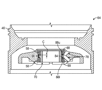
Figure 3A illustrates a diffuser subassembly 64 with parts separated, which
may
facilitate construction of one of the stages 42 (FIG. 2). The diffuser
subassembly 64
generally includes the diffuser body 46, sleeve 56, bushings 58 and lock rings
68. The
diffuser body includes a central bore 70 for receiving the sleeve 56, bearings
58 and lock
rings 68 therein. The central bore 70 includes a rim 72 projecting inwardly
from an inner
surface 73 of the diffuser body 46. The rim 72 does not extend over a full
circumference of
the inner bore 70, but includes interruptions therein to define gaps 74. The
gaps 74 are sized
to circumferentially accommodate tabs 76 of the bushings 58. In operation, the
tabs 76
extend into the gaps 74 such that the tabs 76 circumferentially engage the rim
72 and prohibit
free rotation of the bushings 58 about the longitudinal axis Ao. An optional
fluid flow
passage 78 intersects the rim 72, and permits the passage of fluids into and
out of the central
bore 70 to lubricate and/or cool the sleeve 56.
The sleeve 56 includes a generally cylindrical body portion 80 extending an
axial
length 81 of the sleeve 56. A bore 82 extends axially through the body portion
80 for
receiving the drive shaft 26 (FIG. 2) therein. The bore 82 may include a key
slot 99 or other
geometry for rotationally fixing the sleeve 56 to the drive shaft 26. In other
embodiments,
the bore 82 may be generally smooth. A flange 84 extends radially from a
central region of
the body portion 80. In some embodiments, the central flange 84 may intersect
an axial
center "0" of the body portion 80 of the sleeve 56. The axial center "0" is
disposed half the
axial length 81 from either longitudinal end of the body portion 80. The
central flange 84
defines upper and lower thrust surfaces 88u and 88/, respectively on opposite
sides of the
axial center "0." The upper and lower thrust surfaces 88u and 88/ are axially
separated from
longitudinal ends of the body portion 80. As used herein, the terms "upper"
and "lower" are
relative terms describing portions of an apparatus that may be positioned
above or below one
another, depending on the orientation of the apparatus.
The bushings 58 define axially facing thrust surfaces 90 thereon. An outer
perimeter
92 of the thrust surfaces 90 may engage the rim 72 of the diffuser body 46
when pressed or
otherwise assembled into the central bore 70 of the diffuser body 46. The tabs
76 of the
bushings extend axially from the thrust surfaces 90 and extend into the
circumferential gaps
74 defined in the rim when the bushings 58 are assembled to the diffuser body
46. An inner
perimeter 94 of the trust faces 90 may engage the thrust surfaces 88u, 881 of
the sleeve 56 in
operation to absorb up-thrust and down-thrust forces from the drive shaft 24.
The bushings
5
CA 03092555 2020-08-28
WO 2019/231454
PCT/US2018/035437
58 are illustrated as identical components facing opposite axial directions.
In other
embodiments (see FIG. 4) the bushings may exhibit dissimilar geometries.
The lock rings 68 are arranged to be received in corresponding annular grooves
96
defined in the central bore 70 of the diffuser body 46. The lock rings 68 may
have a c-shaped
or other cross section to provide some flexibility to the lock rings 68 and
permit the lock
rings to be radially compressed for installation into the grooves 96. After
installation, the
lock rings 68 may return to their un-compressed configuration to axially
retain the bushings
58 therebetween. The lock rings may be constructed of various materials such
as stainless
steel, carbon steel, inconel, Ni-resist, etc.
Figure 3B illustrates the diffuser subassembly 64 with parts assembled. The
bushings
58 are pressed into the bore 70 of the diffuser body 46 forming an
interference fit therewith.
In some embodiments, the interference fit may be sufficiently robust for
retaining the
bushings 58 to the diffuser body, and the lock rings 68 are installed to
provide a back-up
retaining mechanism. The sleeve 56 is positioned with the flange 84 captured
axially
between the thrust surfaces 90 of the bushings 58 and radially within the rim
72 of the
diffuser body 46. The rim 72 has a greater axial length than an axial length
of flange 84, and
thus, an axial clearance "C" is defined between the flange 84 and the bushing
58. The fluid
flow passage 78 extends at an oblique angle into the central bore 70 and
intersects the
clearance "C" to permit the fluids passing through the fluid flow passage 78
to lubricate the
flange 84.
In operation, the sleeve 56 with a central flange 84 provides upward and
downward
thrust protection utilizing just one sleeve. When an up-thrust condition is
encountered, the
upper thrust surface 88u of the flange 84 may engage the thrust surface 90 of
an upper
bushing 58. Similarly, when a down-thrust condition is encountered, the lower
thrust surface
88/ of the flange 84 engages the thrust surface 90 of a lower bushing 58. The
thrust surfaces
88u, 88/ and 90 are generally flat and normal to the longitudinal axis Ao.
Thus, thrust loads
may be transferred therebetween while the thrust surfaces 88u, 88/ and 90
rotate with respect
to one another. With the flange 84 disposed generally in the axial center of
the sleeve 56, the
deflection of the sleeve 56 due to moments about the radial support, e.g., the
inner diameter
of the rim 72 (see FIG. 3A), may be reduced with respect to other
configurations. For
example, a greater deflection would be encountered when a sleeve having a
flange on an axial
end thereof (see FIG. 4) absorbs a thrust load at one end, since the opposite
end of the sleeve
would be a greater distance from the thrust load. Thus, by placing the thrust
absorption faces,
6
CA 03092555 2020-08-28
WO 2019/231454
PCT/US2018/035437
e.g., 88u and 88/ at the axial center of the sleeve 56, the deflection of the
sleeve 56 may be
reduced, thereby reducing the wear and fretting of the shaft 24 (FIG. 2).
A single sleeve 56 arranged to absorb both up-thrust forces and down-thrust
force
may also lower the cost of a diffuser subassembly 64, as compared to a dual
sleeve
configuration (see FIG. 4) where two different sleeves are arranged to absorb
either an up-
thrust force or a down-thrust force.
The diffuser subassembly 64 may be pre-assembled in a stable configuration.
Since
the flange 84 is entrained or captured between the two bushings 58 (even
without being
coupled to a drive shaft), the sleeve will be maintained within the diffuser
body 46 during
transport and assembly, thus facilitating assembly of the ESP 20 (FIG. 1).
Capturing a sleeve
during assembly may be less feasible in configurations with a flange at one
end of the sleeve
(see FIG. 4). The diffuser subassembly 64 may be employed in high temperature
wells in
SAGD applications. Generally, only compression pumps having only radial
support bearings
are used since the bushings must be retained in place from the outside.
Because the sleeve 56
and bushings 58 are retained, the subassembly 64 has the capability to provide
radial, upward
and downward thrust protection.
The diffuser subassembly 64 may be constructed by first securing a first one
of the
bushings 58 to the diffuser body 46. For example, the bushing 58 may be press
fit into the
bore 70. Next, the sleeve 56 may be placed in the bore 70 such that the upper
thrust surface
88u on the sleeve is adjacent to the complementary thrust surface 90 defined
on the first
bushing 56. Next, the second bushing 58 may be secured within the bore 70 of
the diffuser
body 46 such that the thrust surface 90 on the second bushing is adjacent the
complementary
lower thrust surface 88/ defined on the sleeve 56 opposite the upper thrust
surface 88u to
thereby capture the sleeve 56 within the bore of the diffuser body 46. The
lock rings 68 may
then be optionally secured in the bore on opposite axial sides of the first
and second bushings
58 to further secure the sleeve within the bore 70.
With the sleeve 56 captured, the sleeve 56 may be coupled to the drive shaft
24 of an
ESP 20 (FIG. 1). For example, the drive shaft 24 may rotationally coupled to
the sleeve 56
by engaging a key slot 98 (FIG. 3A) with a corresponding key 99 (see FIG. 2)
defined on the
drive shaft 24. In other embodiments, (not shown) a key may be defined on the
drive shaft
and a key-slot may be defined sleeve.
7
CA 03092555 2020-08-28
WO 2019/231454
PCT/US2018/035437
Referring now to FIG. 4, an alternate embodiment of a diffuser subassembly 100
is
illustrated including a pair of sleeves 102, 104 disposed within a diffuser
body 106 defining a
longitudinal axis Al. A pair of bushings 108, 110 may be press-fit into the
diffuser body 106,
and one of the sleeves 102, 104 may be supported within a respective one of
the bushings
108, 110. The upper sleeve 102 includes a flange 112 at an upper axial end
thereof, which
may accommodate a down-thrust force of a drive shaft (not shown) extending
through the
sleeve 102. The lower sleeve 104 includes a flange 114 at a lower axial end
thereof, which
may accommodate and up-thrust force of the shaft The flanges 112, 114 arranged
at
longitudinal or axial ends of the sleeves 102, 104 are not axially captured in
the diffuser
subassembly 100, but may be captured when the diffuser subassembly 100 is
assembled into
a larger ESP pump assembly (not shown).
Each of the sleeves 102, 104 includes a key-slot 116 therein, which may
facilitate
rotationally coupling the sleeves 102 to a drive shaft. The drive shaft may
then rotate with
respect to the diffuser body 106 housing about the longitudinal axis to drive
the rotation of an
impeller 44 (FIG. 2).
The aspects of the disclosure described below are provided to describe a
selection of
concepts in a simplified form that are described in greater detail above. This
section is not
intended to identify key features or essential features of the claimed subject
matter, nor is it
intended to be used as an aid in determining the scope of the claimed subject
matter.
In one aspect, the disclosure is directed a diffuser subassembly for a
downhole
submersible pump. The diffuser subassembly includes a diffuser body defining a
bore
extending along a longitudinal axis, the diffuser body including a fluid flow
path around the
bore arranged to reduce a velocity of a fluid flowing therethrough while
increasing a static
pressure of the fluid. An upper bushing is pressed into the bore, and defines
a first thrust
surface on lower surface thereof within the bore. A lower bushing is pressed
into the bore,
and defines a second thrust surface on an upper surface thereof within the
bore. The diffuser
assembly also includes a sleeve for receiving a drive shaft. The sleeve
defines upper and
lower thrust surfaces thereon disposed axially between the first and second
thrust surfaces of
the upper and lower bushings.
In some example embodiments, the upper and lower thrust surfaces are defined
on a
flange extending radially from a sleeve body portion. The flange may intersect
an axial
center of the sleeve body portion.
CA 03092555 2020-08-28
WO 2019/231454
PCT/US2018/035437
In one or more embodiments, the diffuser body defines a circumferential rim
extending radially into the bore, and at least one gap is defined within the
circumferential rim
for receiving a tab of at least one of the first and second bushings to
prohibit free rotation of
the first and second bushings with respect to the diffuser body. The first and
second bushings
.. may be pressed into the diffuser body such that a perimeter of at least one
of the first or
second thrust surfaces engages the circumferential rim.
In some embodiments the diffuser subassembly further includes a pair of lock
rings
disposed on opposite axial sides of the first and second bushings and engaged
with the
diffuser body so as to retain the first and second bushings within the
diffuser body. In some
embodiments, the diffuser body includes a fluid flow passage therein, and the
fluid flow
passage extends at an oblique angle with respect to the longitudinal axis into
the central bore.
According to another aspect, the disclosure is directed to a downhole
submersible
pump. The submersible pump includes an electrical motor and a drive shaft
operably coupled
to the electrical motor for selective rotation of the drive shaft about a
longitudinal axis. An
impeller is coupled to the drive shaft such that rotation of the drive shaft
about the
longitudinal axis rotates the impeller about the longitudinal axis. A diffuser
body is disposed
adjacent the impeller, and the diffuser body defines a bore extending along
the longitudinal
axis and receiving the drive shaft therein. An upper bushing is disposed
within the bore, the
upper bushing defining a first thrust surface on lower surface thereof within
the bore. A
lower bushing is disposed within the bore, the lower bushing defining a second
thrust surface
on an upper surface thereof within the bore. A sleeve receives the drive shaft
therein; the
sleeve defines upper and lower thrust surfaces thereon disposed axially
between the first and
second thrust surfaces of the upper and lower bushings.
In one or more exemplary embodiments, the drive shaft is rotationally coupled
to the
.. sleeve by a keyed slot defined on at least one of the drive shaft and the
sleeve. At least one of
the bushings may be rotationally fixed to the diffuser body by a tab defined
on one of the
diffuser body and the at least one of the bushings extending into a gap
defined on the other of
the diffuser body and the at least one of the bushings. In some embodiments,
the wellbore
pump further includes an impeller and diffuser stack including the impeller
and diffuser body
and at least one additional impeller coupled to the drive shaft and at least
one additional
diffuser body circumscribing the drive shaft.
9
CA 03092555 2020-08-28
WO 2019/231454
PCT/US2018/035437
In some example embodiments, the sleeve may be axially captured within the
bore by
the upper and lower bushings. The sleeve may include a central flange
extending radially
from a sleeve body portion, and the central flange may define the upper and
lower thrust
surfaces thereon disposed axially between the upper and lower bushings. In one
or more
embodiments, the upper and lower bushings may be secured in the diffuser body
by at least
one of an interference fit with the diffuser body and a lock ring disposed on
axial sides of the
first and second bushings.
According to still another aspect, the disclosure is directed to a method of
assembling
a downhole submersible pump. The method includes (a) securing a first bushing
within a
bore of a diffuser body, (b) disposing a sleeve within the bore of the
diffuser body such that
an upper thrust surface on the sleeve is adjacent to a complementary thrust
surface defined on
the first bushing, (c) securing a second bushing within the bore of the
diffuser body such that
a thrust surface on the second bushing is adjacent a complementary lower
thrust surface
defined on the sleeve opposite the upper thrust surface to thereby capture the
sleeve within
the bore of the diffuser body, and (d) coupling, after securing the second
bushing, the sleeve
to a drive shaft of the submersible pump.
In one or more example embodiments, coupling the sleeve to the drive shaft
includes
rotationally coupling the drive shaft to the sleeve by engaging a key on one
of the drive shaft
and the sleeve with a keyslot defined on the other of the drive shaft and the
sleeve. Securing
the first bushing within a bore of a diffuser body may include rotationally
coupling the first
bushing with the diffuser body by inserting a tab defined on the first bushing
with a gap
defined within the diffuser body.
In some embodiments, disposing the sleeve within the bore includes aligning a
central
flange of the sleeve with the thrust surface defined on the first bushing.
Securing the second
bushing within the bore may include aligning the thrust surface on the second
bushing with
the central flange of the sleeve to thereby axially capture the central flange
between the first
and second bushings. Securing the first and second bushings within the bore
may include at
least one of forming an interference fit between the first and second bushing
with the diffuser
body and securing a pair of lock rings on opposite axial sides of the first
and second
bushings.
The Abstract of the disclosure is solely for providing the United States
Patent and
Trademark Office and the public at large with a way by which to determine
quickly from a
CA 03092555 2020-08-28
WO 2019/231454
PCT/US2018/035437
cursory reading the nature and gist of technical disclosure, and it represents
solely one or
more examples.
While various examples have been illustrated in detail, the disclosure is not
limited to
the examples shown. Modifications and adaptations of the above examples may
occur to
those skilled in the art. Such modifications and adaptations are in the scope
of the disclosure.
11