Note: Descriptions are shown in the official language in which they were submitted.
CA 03092655 2020-08-31
WO 2019/166831
PCT/GB2019/050589
1
Combined Power Source For Long Term Operation Of Downhole Gauges
Field of Invention
Described examples relate to systems, methods, and devices for use with wells,
such
as an oil and gas well, and in particular, systems, methods, and devices for
providing
measurements of conditions within a well.
Introduction
Downhole gauges are placed in wells and used to obtain measurements for
transmittal
to the surface. Typically downhole gauges take measurements of variables such
as
temperature and pressure for monitoring conditions within the well. Such
measurements are used by well operators to maintain appropriate operation of
the well.
Data comprising these measurements is sometimes wirelessly transmitted from a
gauge to a surface station. This provides for transmissions to be maintained
whilst a
gauge is in-hole without requiring a dedicated cabling system or the like.
Technologies
such as the Expro CaTSTm system may be used to transmit data using
electromagnetic
waves between a downhole gauge and the surface by utilising well tubing,
structures,
or casing as a transmission medium. Alternatively data may be transmitted
using other
wireless methods such as (but not limited to) by acoustic signals or with flow
modulation techniques.
It is not always economically viable for downhole gauges to be physically
maintained or
otherwise accessible after they have been placed downhole. Therefore, the
useful
lifetime of a downhole gauge of the type described above is restricted by the
capacity
of a battery used to power the gauge. Downhole gauges may be required to
operate for
many years. It is an object of the present invention to provide for an
improved useful
lifetime for a downhole gauge.
Summary of Invention
According to a first aspect of the invention there is provided a downhole
device for use
in a well (e.g. a gauge device). The downhole device may comprises one or more
CA 03092655 2020-08-31
WO 2019/166831
PCT/GB2019/050589
2
electrical systems including at least one measurement means for obtaining
measurement data. The device may comprise a data transmitting means configured
to
transmit measurement data to a receiving station. The device may comprise a
first
power supply configured to supply a first amount of power to any of the one or
more
electrical systems; a second power supply configured to supply a second amount
of
power that is greater than the first amount of power to any of the one or more
electrical
systems; and, means for selectively enabling one or both of the first and
second power
supply.
As used herein, any reference to a measurement means may refer to a sensor
capable
of measuring or detecting a physical property of an environment, in
particular,
temperature and pressure.
Any reference to a transmitting means may refer to a transmitter or set of
transmitting
equipment operable to generate and transmit electromagnetic waves carrying
signals
(either wirelessly or through wires).
Any reference to means for selectively enabling any power supply, or to an
enabling
means, may refer to an electrically actuated switch for electrically
connecting or
disconnecting a power supply to power an electrical circuit and/or for
engaging/disengaging any power supply.
The invention provides for the first power supply used for low power
electrical systems
to be separated from the second power supply to be used for high power
electrical
systems. The use of separate power supplies that are selectively enabled
provides for
power to be used efficiently by the down hole gauge device since each power
supply is
optimised to meet the differing power demands of different electrical systems.
For
example, in many systems a relatively large amount of power will be required
for the
transmitting means compared to a relatively low amount of power required for
the
measurement means or for systems used to maintain the device in a low-power
listening condition.
In one example application, a low-power measurement means may be required to
operate at relatively frequent intervals (for example to obtain measurements
at a 1
second frequency over a long period of time), whilst operators may only
require data to
CA 03092655 2020-08-31
WO 2019/166831
PCT/GB2019/050589
3
be transmitted using a high-power transmission means at relatively infrequent
intervals
(for example once a day or on-demand). The first (lower) power supply may
continuously supply sufficient power to the low-power systems, whilst the
second
(higher) power supply will supply power only when required by the high-power
systems.
In another example application, the first power supply is used to maintain the
device in
a "listening" or "dormant" mode during which the device is operable to receive
an
activation signal to wake up. Once the activation signal is received, the
second power
supply may be used to enable high-power systems that could include measurement
means and/or transmission means.
Optionally, the power supplied by the first power supply is sufficient to
power an
enabling means to enable or disable the second power supply.
Optionally, the first power supply is configured to supply power to the
enabling means
to maintain the enabling means in a listening condition for being operable to
detect an
activation signal and enable the second power supply when the activation
signal is
detected.
Optionally, the second power supply is configured to power the data
transmitting
means.
Optionally, one or both of the first and second power supplies are configured
to supply
power to the measurement means.
Optionally, the one or more electrical systems comprise at least one of a
processing
means and recording means.
As used herein, the term processing means may refer to a processor such as a
central
processing unit or logic circuitry operable to control and execute
computational
operations or instructions. The term recording means may refer to a digital or
analogue
data recorder operable to record data onto a storage medium such as hard
disks,
magnetic tapes or solid state memory.
CA 03092655 2020-08-31
WO 2019/166831
PCT/GB2019/050589
4
Optionally, one or both of the first and second power supply are operable to
be
selectively enabled based on a predetermined timing schedule.
Optionally, the downhole gauge device is configured to receive and/or transmit
signals.
Optionally, the wireless signals comprise acoustic signals.
Optionally, the wireless signals comprise electromagnetic waves that are
propagated
via a metallic well structure.
Optionally, the first power supply comprises a power transmission signal
comprising an
electromagnetic wave that has been propagated via the metallic well structure.
Optionally, the downhole gauge device comprises a rechargeable electrical
storage
device operable to recharge using power of the power transmission signal.
Optionally, the rechargeable electrical storage device is operable to receive
a trickle
charge via the power transmission signal.
Optionally, the wireless signals comprise an activation signal. Optionally,
one or both of
the first and second power supply are configured to be enabled by the
activation signal.
Optionally, the second power supply comprises at least one reserve battery
that is
operable to be enabled and configured to be substantially inert before being
enabled.
Optionally, the at least one reserve battery is configured to be activated
when the
downhole gauge device receives the activation signal, thereby enabling the
data
transmitting means to transmit data.
Optionally, the one or more reserve batteries comprise at least one thermal
reserve or
a liquid reserve battery.
Optionally, the first power supply comprises an atomic battery.
CA 03092655 2020-08-31
WO 2019/166831
PCT/GB2019/050589
Optionally, the first power supply comprises a power generation means that
generates
power from a flow of fluid through the well.
As used herein, the term power generation means may refer to a power generator
5 operable
to generate electrical power. Such a power generator may generate electrical
power by converting kinetic or heat energy into electrical energy via the use
of turbines,
alternators and/or thermoelectric generators.
Optionally, the downhole gauge device further comprises a data receiving means
for
receiving data transmitted by a second downhole gauge device. Optionally, the
transmitting means is configured to transmit the data received by the data
receiving
means to a third downhole gauge device and/or a receiving station.
As used herein, the term receiving means may refer to a data receiver operable
to
receive electromagnetic signals that have originated from a transmitter.
Optionally, the
data receiver decodes such signals into a form that is understood by a device
such as
a data logger or other processing unit.
Optionally, the downhole gauge device further comprises electronic memory
configured
to store data obtained by the data measurement means. Optionally, the
transmitting
means is configured to transmit data stored in the electronic memory.
Optionally, the downhole gauge device is configured to be permanently
installed in a
well.
Optionally, the downhole gauge device is configured to be installed in an
abandoned
well.
According to a second aspect of the invention there is provided a
communication
system for use with a well, the system comprising a downhole gauge device as
described in the first aspect; and, at least one receiving station configured
to be
deployed at a top of the well, and further configured to receive data signals
from the
downhole gauge device.
CA 03092655 2020-08-31
WO 2019/166831
PCT/GB2019/050589
6
Optionally, the at least one receiving station comprises at least one
transceiver
configured to transmit electrical power to the downhole gauge device via a
metallic
structure of the well.
Optionally, the at least one surface receiver is further configured to embed
an
activation signal into a activation-embedded power transmission signal and to
transmit
the activation-embedded power transmission signal to the downhole gauge
device,
wherein the downhole gauge device is configured to transmit data to the
surface
receiver when the downhole gauge device receives the activation-embedded power
transmission signal.
According to a third aspect of the invention there is provided a method of
operating a
downhole gauge device located in a well, the method comprising the step of
selectively enabling one or both of;
a first power supply of the downhole gauge;
and a second power supply of the downhole gauge device to supply a greater
amount of power than the first power supply. The method also includes the
steps of
obtaining measurement data using measurement means and transmitting data to a
receiving station using a data transmitting means.
Optionally, the method further comprises the step of powering an enabling
means by
the first power supply for enabling or disabling the second power supply.
Optionally, the method further comprises the step of powering an enabling
means by
the first power supply for maintaining the enabling means in a listening
condition for
being operable to detect an activation signal and enable the second power
supply
when the activation signal is detected.
Optionally, the method further comprises the step of transmitting an
activation signal
from a receiving station to the downhole gauge device, wherein at least one of
the first
and second power supply is enabled when the downhole gauge device receives the
activation signal.
CA 03092655 2020-08-31
WO 2019/166831
PCT/GB2019/050589
7
Optionally, the first power supply comprises an electrical power transmission
signal
transmitted to the downhole gauge device from the surface receiver as
electromagnetic
waves via a metallic structure of the well.
Optionally, the method further comprises the step of embedding the activation
signal
into the electrical power transmission signal.
Optionally, the method further comprises the step of charging a rechargeable
device of
the first power supply of the downhole device using the electrical power
transmission.
Optionally, the method further comprises the step of transmitting data
obtained by the
measurement means of the downhole gauge device from the downhole gauge device
to the receiving station.
Optionally, the method further comprises the step of transmitting data from
the
downhole gauge device occurs when the activation signal is received by the
downhole
gauge device.
Optionally, the method further comprises the step of activating a reserve
battery of the
second power supply when the activation signal is received by the downhole
gauge
device.
Optionally, the downhole gauge device is permanently installed in the well.
Optionally, the downhole gauge device is operated in an abandoned well.
The invention includes one or more corresponding aspects, embodiments or
features in
isolation or in various combinations whether or not specifically stated
(including
claimed) in that combination or in isolation. As will be appreciated, features
associated
with particular recited embodiments relating to devices may be equally
appropriate as
features of embodiments relating specifically to systems or methods of
operation, and
vice versa.
CA 03092655 2020-08-31
WO 2019/166831
PCT/GB2019/050589
8
It will be appreciated that one or more embodiments/aspects may be useful in
effective
monitoring of a well, and may help monitor conditions accurately during the
life of any
well.
The above summary is intended to be merely exemplary and non-limiting.
Brief Description of the Figures
A description is now given, by way of example only, with reference to the
accompanying drawing, in which Figure 1 shows a diagrammatic representation of
each of four stages (labelled A, B, C, and D) of an exemplary method of use of
an
exemplary device incorporated into exemplary methods and systems according to
the
invention.
Detailed Description
The following examples may be described in relation to oil and gas wells, and
in
particular production and appraisal wells. The same devices, methods, systems,
etc.,
may be used beyond oil and gas applications. A skilled reader will be able to
implement
those various alternative embodiments accordingly.
Generally, disclosed herein are devices, methods and systems for efficiently
managing
the electrical resources available to a downhole gauge device that is operable
to obtain
measurements of environmental conditions and transmit the measurements to a
receiver station. This provides for a downhole gauge to have an enhanced
useful
lifetime without requiring any further physical interaction with the downhole
gauge after
it has been sealed downhole.
It will be appreciated given the following examples that the devices described
herein
may be installed together with a well installation at the time of completion,
or indeed
deployed later in the lifecycle of a well. In some cases, the devices may be
provided
during an abandonment process, e.g. in order to monitor well conditions after
the well
has been abandoned (e.g. as may be required). In any event, in many
circumstances
the devices may be considered to be deployed permanently in the well, or at
least for a
significant period of time. In some cases, the devices may be initially
installed in the
CA 03092655 2020-08-31
WO 2019/166831
PCT/GB2019/050589
9
well, and then activated (or enabled further) sometime later ¨ which may be
significantly later (e.g. months, years). A skilled reader will appreciate
that such long-
term deployment may be different from, for example, devices that are not
intended to
be permanently installed, such as those that may be run as part of a drilling
or
intervention operation, and then removed from the well.
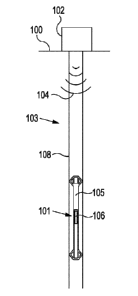
Figures 1(a-d) shows four simplified representations of a section of a well
103 including
a downhole gauge 101. Each of Figures 1(a-d) represents a condition of
communication between a downhole gauge 101 and receiving station 102 for each
of
four different steps of an exemplary method of powering the downhole gauge.
With reference to Figures 1 (a-d), a metallic well structure 108 extends from
a ground
surface 100 to a subterranean formation, as will be appreciated. Such well
structure
108 can include conductor, casing and other tubing used to recover product
from the
formation.
Downhole gauge 101 comprises first power supply 105 and second power supply
106.
First power supply 105 is operable to supply power to pressure and temperature
sensors (not shown) of the downhole gauge 101. Second power supply 106 is
operable
to supply power to a transmitting means (not shown) of the downhole gauge 101.
Receiving station 102 is operable to transmit a power transmission signal 104
that is
propagated via metallic well structure 108 as shown in Figures la, 1 b, and
id. In other
words, the metallic well structure 108 itself forms the signal path, rather
than a
dedicated cabling system or the like. Receiving station 102 is further
operable to
transmit an activation signal 104a as represented in Figure lb. The activation
signal
104a is embedded into power transmission signal 104. As shown in Figure lc,
downhole gauge 101 is operable to transmit data signals 107. In the shown
embodiment the data signals are propagated via the metallic structure 108.
However
they could be acoustic signals or any other type of wireless/wired signal.
Data signals
107 comprise measurements obtained by sensors on the gauge. These measurements
are typically pressure and temperature readings.
A processing means (not shown) within the downhole gauge 101 provides for
inbound
signals such as the activation signal to be interpreted, and, for measurement
data to be
CA 03092655 2020-08-31
WO 2019/166831
PCT/GB2019/050589
converted into a form suitable for transmission as a data signal. In the shown
embodiment the processing means is powered by the first power supply, and, in
other
embodiments may be powered by the second power supply.
5 A method of powering a downhole gauge will now be described with
reference to the
Figures 1(a-d).
With reference to Figure la, power transmission signal 104 is transmitted to
the
downhole gauge 101 by receiving station 102. Power transmission signal 104 is
10 propagated via metallic structure 108. Downhole gauge 101 receives the
power
transmission signal and the power of the power transmission signal is supplied
to the
first power supply 105. It will be appreciated that there is a significant
limitation on the
level of power that can be transmitted in this way. The level of power
transmitted is
limited by factors such as the conductivity and physical properties of the
metallic
structure of the well. In one embodiment, the power supplied by the first
power supply
is sufficient to run the measurement means. The first power supply may
comprise
rechargeable batteries or capacitors that are operable to recharge using the
transmitted power. In another embodiment, the power supplied by the first
power
supply is sufficient to maintain the downhole gauge in a "listening" or
"dormant" mode
where low-power signal detection systems (not shown) of the gauge are operable
to
listen for an activation signal.
In some embodiments, the first power supply comprises a nuclear (atomic)
battery (not
shown) that is utilised in combination with energy provided by the power
transmission
signal, or, provides power for the measurement means by itself.
In some embodiments, the first power supply comprises a power generation means
(not shown) that converts energy obtained from the environment (such as
thermal
energy or well fluid flow energy) to electrical power for the measurement
means.
It will be appreciated that the method described with reference to Figure 1 a
can be
applied for a significant period of time whilst the downhole gauge 101 is not
required to
transmit measurements. For example it may be many years after a downhole gauge
is
sealed in position before it is required to provide measurement readings.
Power
transmission signal 104 may provide a trickle charge to a battery of the first
power
CA 03092655 2020-08-31
WO 2019/166831
PCT/GB2019/050589
11
supply 105 during this time to ensure that there is always sufficient power
available for
the measurement means to be initiated at any time.
In this respect, the downhole gauge 101 may be intended to form part of an
initial well
installation. Furthermore, and as mentioned above, the downhole gauge 101 may
form
part of an integrated system that may be installed in the well during any
stage of
production or abandonment of the well for long term deployment. In some cases,
an
operator need not know at the time of installation of the downhole gauge 101
when it
will be required for use.
With reference to Figure lb an activation signal 104a is transmitted to the
downhole
gauge 101. In the embodiment of Figures 1(a-d), the activation signal 104a is
embedded within the power transmission signal 104. The activation signal 104a
may
be transmitted in response to a request for data by a user. The second power
supply is
configured to be enabled when the downhole gauge receives the activation
signal
104a.
With reference to Figure lc, after the second power supply has been enabled,
data
signals 107 are transmitted by the downhole gauge 101 to receiving station
102. This
transmission is powered by the second power supply. It will be appreciated
that the
data signals 107 can be propagated as electromagnetic signals via the metallic
structure of the well, or, data signals 107 could be transmitted by any other
known
means such as by using acoustic signals.
The second power supply 106 comprises a reserve battery (not shown). The
reserve
battery has effectively a 0% self-loss. In other words, it minimally
discharges during the
time before it is activated. Examples of reserve batteries that may be used
include
thermal or liquid reserve batteries. Typically, the reserve batteries can be
activated by
one of adding water, electrolyte, or by heating solid electrolyte to a
temperature at
which it becomes conductive. Use of the reserve battery provides for power to
be
stored for a long period of time such as over many years. Upon activation of
the
reserve battery due to the activation signal, power is provided to the
transmission
means. The reserve battery typically comprises substantially more power than
that
provided by the first power supply, and, provides enough power to enable a
transmission using the transmission means. The second power supply 106 may
include
CA 03092655 2020-08-31
WO 2019/166831
PCT/GB2019/050589
12
a plurality of reserve batteries, each battery being configured to be
activated when one
or more transmissions are required.
In some embodiments, the second power supply is used to power a high-power
measurement means or other systems that require more power than is provided by
the
first power supply.
It will be appreciated that the invention provides for selectively enabling
the first and
second power supplies in a method such as that described above. This provides
for
more efficient usage of available power compared to methods available where
there is
a single power supply. For example, initiation of a single power supply for
both
measurement and transmission would result in unfavourable discharge over time
of
such a single power supply during the time that measurements are recorded,
but,
transmission is not required.
With reference to Figure id, the downhole gauge has completed transmission of
data,
and the downhole gauge continues to utilise the first power supply to run low-
power
systems such as the measurement means and/or signal detection means. When the
downhole gauge receives a further activation signal 104a, the communication
conditions shown in Figures lb and lc will occur as discussed above.
The methods of communication and downhole gauge discussed above with reference
to Figures 1(a-d) facilitate a variety of advantageous methods and systems for
enhancing the usable lifetime of a downhole gauge device 101.
In a further embodiment, the second power supply is enabled based on a timing
mechanism (not shown).
In a further embodiment, the downhole gauge comprises electronic memory for
storing
a collection of measurement data that has been obtained over a period of time.
In this
embodiment, the downhole gauge device is configured to transmit the collection
of
measurement data using the transmission means when the activation signal is
received.
CA 03092655 2020-08-31
WO 2019/166831
PCT/GB2019/050589
13
In a further embodiment, the downhole gauge device is configured to lie in a
dormant
condition for a long time, such as many months or even years. The power
supplies of
the downhole gauge device may be initiated by transmittal of the power
transmission
signal and/or transmittal of the activation signal. It will be appreciated
that in such
dormant state, there is effectively a 0% loss of power stored in any power
supplies,
since any reserve batteries of the second power supply are not yet activated.
In a further embodiment, a system according to the invention includes multiple
downhole gauge devices including a first and second power supply as described
above, wherein some of the downhole gauge devices act as repeaters. For
example, a
first downhole gauge device is initiated by a signal from the receiving
station. The first
downhole gauge device transmits a signal for initiating a second downhole
gauge
device that is located deeper within a well. The second downhole gauge device
transmits measurements to the receiving station via the first downhole gauge
device
using the second power supply of each downhole gauge device.
It will be appreciated that while in the above examples, the systems and
methods have
been described in relation to gauge devices, e.g. for measuring/communicating
P/T
data, it will be appreciated that in other examples, the power supply
arrangements (e.g.
first and second power supplies as described above) may be used for different
applications when installed (e.g. permanently installed) in a well
installation. A skilled
reader will readily be able to implement those alternative embodiments.
Further, the applicant discloses in isolation each individual feature
described herein
and any combination of two or more such features, to the extent that such
features or
combinations are capable of being carried out based on the specification as a
whole in
the light of the common general knowledge of a person skilled in the art,
irrespective of
whether such features or combinations of features solve any problems disclosed
herein, and without limitation to the scope of the claims. The applicant
indicates that
aspects of the invention may consist of any such individual feature or
combination of
features. In view of the foregoing description it will be evident to a person
skilled in the
art that various modifications may be made within the scope of the invention.