Note: Descriptions are shown in the official language in which they were submitted.
86954723
TISSUE RETRACTION DEVICE AND DELIVERY SYSTEM
CROSS-REFERENCE TO RELATED APPLICATIONS
[0001] This application claims the benefit of priority of U.S.
Provisional
Application No. 62/665,441, filed May 1, 2018,
TECHNICAL FIELD
[0002] The present disclosure pertains to medical devices, and methods
for
manufacturing medical devices. More particularly, the present disclosure
pertains to a
tissue retraction device and related delivery system.
BACKGROUND
[0003] A wide variety of intracorporeal medical devices have been
developed for
medical use, for example, intravascular use. Some of these devices include
guidewires,
catheters, and the like. These devices are manufactured by any one of a
variety of
different manufacturing methods and may be used according to any one of a
variety of
methods. Of the known medical devices and methods, each has certain advantages
and
disadvantages. There is an ongoing need to provide alternative medical devices
as well
as alternative methods for manufacturing and using medical devices.
BRIEF SUMMARY
[0004] This disclosure provides design, material, manufacturing
method, and use
alternatives for medical devices. An example tissue retraction device includes
a first
tissue engagement member coupled to an elastic member by a coupling assembly.
The
coupling assembly including a first coupler body having a first end region and
a first
compression member. Further, the first end region of the first coupler body is
configured to extend into a portion of a lumen of the elastic member and the
compression member is designed to compress the elastic member onto the first
coupler
body such that the elastic member is fixedly engaged with the coupler body.
[0005] Alternatively or additionally to any of the embodiments above,
wherein the
first end region of the first coupler body includes a channel extending around
the
circumference thereof.
1
Date Recue/Date Received 2022-02-07
CA 03003011 2020-09-02
WO 2019/213126
PCT/US2019/029986
[0006] Alternatively
or additionally to any of the embodiments above, wherein the
first compression member is designed to compress the elastic member into at
least a
portion of the channel of the first coupler body.
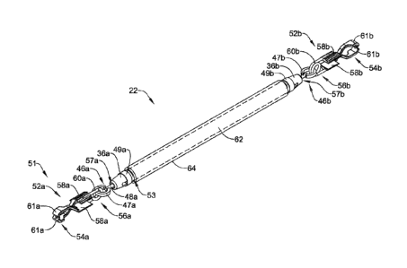
[0007] Alternatively
or additionally to any of the embodiments above, wherein the
compression member includes a compression ring.
[0008] Alternatively
or additionally to any of the embodiments above, wherein the
compression member includes a suture.
[0009] Alternatively
or additionally to any of the embodiments above, wherein the
coupling assembly further comprising a connection member, wherein the
connection
member is designed to couple the coupler body to the first tissue engagement
member.
[0010] Alternatively
or additionally to any of the embodiments above, wherein the
connection member includes a post member and an attachment member, wherein a
first
end region of the post member is coupled to the attachment member, and wherein
the
post member is configured to extend through an aperture of the coupler body.
[0011] Alternatively
or additionally to any of the embodiments above, wherein the
post member further includes a second end region opposite the first end
region, and
wherein the first end region of the post member includes a first diameter, and
wherein
the second end region of the post member includes a second diameter larger
than the
first diameter,
[0012] Alternatively
or additionally to any of the embodiments above, wherein the
aperture includes a first inner diameter, and wherein the second diameter of
the post
member is larger than the first inner diameter of the aperture.
[0013] Alternatively
or additionally to any of the embodiments above, wherein the
first tissue engagement member includes a first tissue engagement portion and
a first
spring, and wherein the attachment member is designed to engage the first
spring.
[0014] Alternatively
or additionally to any of the embodiments above, wherein the
attachment member is substantially C-shaped.
[0015] Alternatively
or additionally to any of the embodiments above, wherein the
attachment member includes a first fitting and a second fitting, and wherein
the first
fitting and the second fitting are designed to mate with one another.
[0016] Alternatively
or additionally to any of the embodiments above, wherein the
first fitting and the second fitting are designed to couple the first spring
with the first
end region of the post member.
2
CA 03003011 2020-09-02
WO 2019/213126
PCT/US2019/029986
[0017] Alternatively or additionally to any of the embodiments above,
further
comprising a second tissue engagement member, and wherein the elastic member
extends between the first tissue engagement member and the second tissue
engagement
member.
[0018] Alternatively or additionally to any of the embodiments above,
further
comprising a tubular support member including a lumen extending therein, and
wherein
at least a portion of the elastic member extends within the lumen of the
support member.
[0019] Alternatively or additionally to any of the embodiments above,
wherein the
support member is positioned between the first tissue engagement member and
the
second tissue engagement member.
[0020] Another tissue retraction device includes:
a first tissue clip coupled to an elastic member by a first coupling assembly,
and a second tissue clip coupled to the elastic member by a second coupling
assembly, and wherein the first and second coupling assemblies each include:
a coupler body having a first end region; and
a compression member;
wherein the first end region of each of the coupler bodies is configured to
extend into a portion of the lumen of the elastic member;
wherein each of the compression members are designed to compress the
elastic member onto each of the coupler bodies such that the elastic nriember
is fixedly
engaged to each of the coupler bodies.
[0021] Alternatively or additionally to any of the embodiments above,
wherein the
first end region of the each of the coupler bodies includes a channel
extending
around the circumference thereof.
[0022] Alternatively or additionally to any of the embodiments above,
wherein each
of the compression members is designed to compress the elastic member within
at
least a portion of the channel of each of the coupler bodies.
[0023] A method of dissecting tissue includes:
advancing a tissue retraction device to a target site, the tissue retraction
device
including:
a first tissue engagement member coupled to an elastic member by a
coupling assembly, the coupling assembly including:
a first coupler body having a first end region; and
3
86954723
a first compression member;
wherein the first end region of the first coupler body is configured to extend
into a
portion of a lumen of the elastic member;
wherein the compression member is designed to compress the elastic member onto
the first coupler body such that the elastic member is fixedly engaged with
the coupler body;
manipulating the first tissue engagement member between a first configuration
and a second
open configuration; and
attaching the first tissue engagement member to the target site.
[0023a] Some embodiments disclosed herein provide a tissue retraction
device, comprising:
a first tissue engagement member including movable jaws, the first tissue
engagement member
coupled to an elastic member by a coupling assembly, the coupling assembly
including:
a first coupler body having a first end region; and
a first compression member;
wherein:
the first end region of the first coupler body is configured to extend into a
portion of a lumen
of the elastic member; and
the compression member is designed to compress the elastic member onto the
first coupler
body such that the elastic member is fixedly engaged with the coupler body.
[002313] Some embodiments disclosed herein provide a tissue retraction
device, compising:
a first tissue clip rotatably coupled to an elastic member by a first coupling
assembly, the first
coupling assembly including:
a coupler body having a first end region; and
a compression member;
wherein:
the first end region of the coupler body is configured to be attached to the
elastic member.
100241 The above summary of some embodiments is not intended to describe
each disclosed
embodiment or every implementation of the present disclosure. The Figures, and
Detailed
Description, which follow, more particularly exemplify these embodiments.
4
Date recue/Date received 2023-05-03
86954723
BRIEF DESCRIPTION OF THE DRAWINGS
[0025] The disclosure may be more completely understood in consideration
of the
following detailed description in connection with the accompanying drawings,
in which:
[0026] FIG. 1 is a partial cross-sectional side view of an example tissue
retraction device
positioned within a body lumen;
[0027] FIG. 2 is a perspective view of an example tissue retraction
device;
[0028] FIG. 3 is an exploded view of the example tissue retraction device
shown in
FIG. 2;
[0029] FIG. 4 illustrates an example tissue engagement member;
[0030] FIG. 5 is a perspective view of another example tissue retraction
device;
[0031] FIG. 6 is an exploded view of the example tissue retraction device
shown in
FIG. 5;
[0032] FIGS. 7-9 illustrate example tissue engagement members;
[0033] FIGS. 10-14 illustrate a methodology for deploying and attaching
an example
tissue retraction device.
[0034] While the disclosure is amenable to various modifications and
alternative forms,
specifics thereof have been shown by way of example in the drawings and will
be described
in detail. It should be understood, however, that the intention is not to
4a
Date recue/Date received 2023-05-03
CA 03003011 2020-09-02
WO 2019/213126
PCT/US2019/029986
limit the disclosure to the particular embodiments described. On the contrary,
the
intention is to cover all modifications, equivalents, and alternatives falling
within the
spirit and scope of the disclosure.
DETAILED DESCRIPTION
[0035] For the
following defined terms, these definitions shall be applied, unless a
different definition is given in the claims or elsewhere in this
specification.
[0036] All numeric
values are herein assumed to be modified by the term "about",
whether or not explicitly indicated. The term "about" generally refers to a
range of
numbers that one of skill in the art would consider equivalent to the recited
value (e.g.,
having the same function or result). In many instances, the terms "about" may
include
numbers that are rounded to the nearest significant figure.
[0037] The
recitation of numerical ranges by endpoints includes all numbers within
that range (e.g. Ito 5 includes 1, 1.5, 2, 2,75, 3, 3.80, 4, and 5).
[0038] As used in
this specification and the appended claims, the singular forms
"a", "an", and "the" include plural referents unless the content clearly
dictates
otherwise. As used in this specification and the appended claims, the term
"or" is
generally employed in its sense including "and/or" unless the content clearly
dictates
otherwise.
[0039] It is noted
that references in the specification to "an embodiment", "some
embodiments", "other embodiments", etc., indicate that the embodiment
described may
include one or more particular features, structures, and/or characteristics.
However,
such recitations do not necessarily mean that all embodiments include the
particular
features, structures, and/or characteristics. Additionally, when particular
features,
structures, and/or characteristics are described in connection with one
embodiment, it
should be understood that such features, structures, and/or characteristics
may also be
used in connection with other embodiments whether or not explicitly described
unless
clearly stated to the contrary.
[0040] The following
detailed description should be read with reference to the
drawings in which similar elements in different drawings are numbered the
same. The
drawings, which are not necessarily to scale, depict illustrative embodiments
and are
not intended to limit the scope of the invention.
CA 03003011 2020-09-02
WO 2019/213126
PCT/US2019/029986
[0041] A number of
medical procedures, including intravascular procedures,
procedures along the digestive and/or biliary tract, thoracic procedures, etc.
utilize
medical devices to access tissue intended for removal (e.g., "target tissue")
within the
body. For example, in some current medical procedures (e.g., Endoscopic
Submucosal
Dissection (ESD), Peroral Endoscopic Myotomy (POEM), cholecystectomy, Video-
Assisted Thoracoscopic Surgery (VATS)), physicians may utilize an endoscope or
similar medical device to access and remove cancerous lesions. Further, as
part of the
procedure, the physician may utilize an endoscope capable of both accessing
the target
tissue site while also permitting a cutting device to be deployed therethrough
to excise
the target tissue. Additionally, in some instances, the endoscope may
incorporate
features which assist the physician in visualizing and performing the tissue
dissection
procedure. For example, some endoscopes may include a light and/or camera
designed
to illuminate the body lumen as the scope is navigated and positioned adjacent
to the
target tissue site. Additionally, some endoscopes may also include a lumen
(e.g., a
working channel) through which a cutting member or other accessory medical
devices
may be deployed and utilized.
[0042] While
physicians are becoming more proficient at extracting cancerous
lesions from within the body (e.g., within the digestive tract, abdominal
cavity, thoracic
cavity, etc.), the extraction methods continue to be inefficient and time-
consuming. For
example, in some instances poor visualization of the tissue dissection process
may
result in a prolonged tissue dissection procedure. In another example, the
actual tissue
that the physician is attempting to dissect may, itself, obstruct the pathway
of the tools
which the physician is using during the procedure. Therefore, in some
instances it may
be desirable to utilize a medical device which assists in improving the
visualization of
the target tissue while also mitigating the obstruction of dissection tools
the physician
is utilizing. Therefore, in some instances it may be desirable to utilize a
tissue retraction
device which lifts and retracts the region of tissue to be dissected by the
physician.
Disclosed herein are medical devices such as a tissue retraction device and
delivery
system that are designed to lift and retract the target tissue.
[0043] FIG. 1 is a
partial cross-sectional side view of an example tissue retraction
delivery system 10 including a distal portion 12 and a proximal portion 14.
FIG. 1
shows the distal portion 12 of the tissue retraction system 10 positioned
within an
example body lumen 16. Further, FIG. I shows that the proximal portion 14 of
the
6
CA 03003011 2020-09-02
WO 2019/213126
PCT/US2019/029986
tissue retraction system 10 may extend out of the body lumen 16 to a position
outside
the body. As shown in FIG. 1, the tissue retraction system may include a
tissue
retraction device 22. Additionally, the tissue retraction system 10 may
include a
delivery catheter 26. The delivery catheter 26 may be constructed from a semi-
rigid or
compliant material such as a thermoplastic elastomer, silicone rubber, nylon,
polyurethane, polyethylene terephthalate (PET), latex, or similar materials.
The
delivery catheter 26 may have a distal end region 28 and a proximal end region
30.
Further, a lumen 32 may extend through the delivery catheter 26 from proximal
end
region 30 to the distal end region 28. As illustrated, the tissue retraction
device 22 may
be positioned along the distal end region 28 and within the lumen 32 of the
delivery
catheter 26.
[0044] Additionally,
FIG. I illustrates that the delivery catheter 26 (including the
tissue retraction device 22) may extend through an example medical device 18.
As
discussed above, in FIG. 1 the medical device 18 may take the form of an
endoscope,
laproscope, needle, catheter, guide tube, or the like. The medical device 18
may include
a distal portion 23 and a proximal portion 25. Further, FIG. 1 illustrates
that the distal
portion 23 of the medical device 18 may be advanced within a portion of a body
lumen
1610 a position adjacent a target tissue 50, such as a lesion, while the
proximal portion
25 of the medical device 18 may extend out of the body lumen 16 to a position
outside
the body.
[0045] Medical
device 18 may include a lumen 21 extending from the proximal
portion 25 to the distal portion 23 of the medical device 18. In some
examples, the
lumen 21 may be referred to as the "working channel" of the medical device 18.
The
lumen 21 may be designed to permit a variety of medical devices to pass
therethrough.
For example, a physician may pass or exchange a variety of medical devices
through
the working channel 21 over the course of a given medical procedure. For
example, as
illustrated in FIG. 1. the delivery catheter 26 (including the tissue
retraction device 22)
may extend through the lumen 21 of the medical device 18. In other words, FIG.
1
illustrates that a physician may insert the distal end 28 of the delivery
catheter 26 into
the proximal portion 25 of the medical device 18 (which is outside the body),
advance
the delivery catheter 26 through the lumen 21 whereby the distal end 28 of the
delivery
catheter may eventually extend out of the distal portion 23 of the medical
device 18 to
a position adjacent the target tissue 50.
7
CA 03003011 2020-09-02
WO 2019/213126
PCT/US2019/029986
[0046] The proximal
end 30 of the delivery catheter 26 may include a control
member 42. The control member 42 may be utilized as a grip to control the
translation
of the delivery catheter 26. Further, the control member 42 may also permit a
user to
rotate the delivery catheter 26. As will be described in greater detail below,
the control
member 42 may be utilized by a physician to advance the distal end 28 of the
delivery
catheter 26 to a position adjacent a target tissue 50 prior to deploying the
tissue
retraction device 22 from the distal end 28 of the delivery catheter 26.
[0047] In some
examples, the medical device 18 may include additional features.
For example, the medical device 18 shown in FIG. 1 may include an accessory
feature
20 (e.g., light, camera etc.) positioned on the distal portion 23 of the
medical device
18. Further, other medical devices 18 having additional features may be
utilized in
conjunction with the tissue retraction system 10.
[0048] As
illustrated in FIG. 1, in some examples the tissue retraction system 10
may include a manipulating device 34 ("manipulator") designed to advance
(e.g., push,
deploy, etc.) the tissue retraction device 22 out of the distal end 28 of the
delivery
catheter 26. As will be described in greater detail below, once the
manipulator 34 has
pushed the tissue retraction device 22 out of the delivery catheter 26, it may
also be
used to position and/or manipulate the tissue retraction device 22 within the
body lumen
16.
[0049] As shown in
FIG. 1, the manipulator 34 may extend within the lumen 32 of
the delivery catheter 26. In other words, FIG. 1 illustrates that a distal end
38 of the
manipulator 34 may extend from the proximal end 30 of the delivery catheter 26
(which
is outside the body), through the lumen 32 of the delivery catheter 26 whereby
the distal
end 38 of the manipulator 34 may be positioned adjacent the proximal end of
the tissue
retraction device 22.
[0050] The proximal
end 40 of the manipulator 34 may include a handle member
44. Handle member 44 may include one or more finger grips 45 which permit a
user
to grasp and thereby advance (e.g., translate) the distal end 38 of the
manipulator within
the lumen 32 of the delivery catheter 26. in other words, by grasping and
manipulating
the handle 44, a user may be able to translate the manipulator 34 along the
longitudinal
axis of the delivery catheter 26. The handle design illustrated in FIG. 1 is a
schematic.
Other handle designs are contemplated. For example, handle designs that
include
8
CA 03003011 2020-09-02
WO 2019/213126
PCT/US2019/029986
different grip arrangements, ergonomic features, etc. that may be utilized
with the tissue
retraction system 10 (and components thereof) described herein are
contemplated.
[0051] The distal
end 38 of the manipulator 34 may include a grasping member 39
(e.g., forceps, jaws, etc.). When positioned within the lumen 32 of the
delivery catheter
26, the grasping member 39 may be in a closed position (e.g., the jaws of the
grasping
member 39 may be closed and contacting one another). Further, the handle
member 44
may be designed to control the opening and/or closing of the grasping member
39. In
other words, when the grasping member 39 is advanced to a position outside of
the
lumen 32 of the delivery catheter 26, a user may manipulate the handle member
44 to
open and/or close the grasping member 39.
[0052] As described
above, the manipulator 34 may be utilized to deploy the tissue
retraction device 22 out of the distal end 28 of the delivery catheter 26.
Specifically, it
can be appreciated that, when positioned adjacent to tissue target 50, a user
may
advance the manipulator 34 in a proximal-to-distal direction within the lumen
32 of the
delivery catheter 26 such that the grasping member 39 may contact and push the
proximal end of the tissue retraction device 22 out of the distal end 28 of
the delivery
catheter 26.
[0053] In at least
some examples contemplated herein, the manipulator 34 and the
tissue retraction device 22 may be positioned within the delivery catheter 26
as depicted
in FIG. I prior to the delivery catheter 26 being advanced through the lumen
21 of the
medical device 18. In other words, in some examples, both the manipulator 34
and the
tissue retraction device 22 may be "pre-loaded" into the delivery catheter 26
prior to
being inserted and advanced through the working channel 21 of the medical
device 18
to a position adjacent to target tissue 50. In other examples, however, only
the tissue
retraction device 22 may be preloaded into the delivery catheter 26 and
advanced within
the lumen 21 of the medical device 18 to a position adjacent to target tissue
50, after
which the manipulator 34 may be separately inserted into the lumen 21 of the
medical
device 18 and advanced to a position in which grasping member 39 is adjacent
and/or
contacting the proximal end of the tissue retraction device 22.
[0054] It can be
appreciated from the above discussion that the tissue retraction
system 10 may be designed such that the delivery catheter 26 and the
manipulator 34
may be moved (e.g., translated, rotated, etc.) relative to one another. For
example, once
the distal end 28 of the delivery catheter 26 is positioned adjacent to the
target tissue 50
9
CA 03003011 2020-09-02
WO 2019/213126
PCT/US2019/029986
(with the manipulator 34 positioned adjacent to the distal end of the tissue
retraction
device 22), a user may grasp both the control member 42 and the handle member
44.
This may permit the user to maintain the distal end 28 of the delivery
catheter 26 in a
fixed position while advancing the manipulator 34 in a distal direction such
that the
grasping member 39 moves distally relative to the distal end 28 of the
delivery catheter
26. It can be appreciated that this relative movement may push the tissue
retraction
device 22 out of the distal end 28 of the delivery catheter 26.
[0055] In other
examples, it can be appreciated that instead of a user advancing the
manipulator 34 in a distal direction to deploy the tissue retraction device
22, the user
may, alternatively, retract the delivery catheter 26 while maintaining the
manipulator
34 in a fixed position. The retraction of the delivery catheter 26 may
"uncover" the
tissue retraction device 22, thereby releasing it from the lumen 32 of the
delivery
catheter 26.
[0056] FIG. 2
illustrates an example tissue retraction device 22. The tissue
retraction device 22 may include one or more engagement members 51 (e.g.,
clip, clasp,
fastener, clamp, etc.). For example, FIG. 2 illustrates that the tissue
retraction device
22 may include a first engagement member 52a and a second engagement member
52b.
The first engagement member 52a may include a first end 54a and a second end
56a.
The first end 54a may include one or more jaws 61a (e.g., end effectors). The
jaws 61a
may be designed such that they move relative to one another. FIG. 2 further
illustrates
that the second end 56a of the first engagement member 52a may include a
spring 60a.
It can be appreciated that the spring 60a may be designed to provide a
compressive
force that is translated through the body of the first engagement member 52a
to the jaw
members 61a, thereby biasing the jaw members 61a in a closed position (e.g., a
position
in which the jaw members 61a are contacting one another).
[0057] In some
examples, the ends of the jaw members 61a may not necessarily
contact one another while in a closed position. The jaw members 61a may be
spaced
apart from one another while in a closed position. Spacing the jaw members 61a
apart
from one another while in a closed position may permit additional compressive
force
to be generated when in contact with tissue. This additional compressive force
could be
termed "preload." The range of preload forces could vary from about 5 grams of
force
to about 200 grams of force, or about 15 grams of force to about 40 grams of
force.
CA 03003011 2020-09-02
WO 2019/213126
PCT/US2019/029986
[0058] It can be
appreciated that the engagement members 51 depicted in the
examples disclosed herein are schematic. In other words, it is contemplated
that the
engagement members 51 described herein may include alternative design
arrangements, features, geometries etc. without departing from the scope of
the
examples contemplated herein. For example, it is contemplated that the spring
60a of
the first engagement member 52a may be positioned between the first end 54a
and the
second end 56a of the first engagement member 52a). Additionally, it is
contemplated
that the jaws (e.g., end effectors) may have a variety of different shapes
and/or
geometries without departing from the scope of the examples contemplated
herein.
Other variations are contemplated.
[0059] FIG. 2
further illustrates that the first engagement member 52a may include
one or more gripping members 58a. For example, FTC]. 2 illustrates that the
gripping
member 58a may be formed from the same material as the jaw member 61a. In
other
words, the jaw 61a and the gripping member 58a may be formed as a monolithic
component. For example, the jaws 61a (e.g., end effectors) and the gripping
members
may be metal injection molded (MIM), conventionally machined, stamped,
additive
manufactured or the like. However, this is not intended to be limiting.
Rather, it is
contemplated that the jaw 61a and the gripping member 58a may be formed as two
separate components which are attached (e.g., welded, glued, press fit, etc.)
together to
form the structure shown in FIG. 2. Additionally, FIG. 2 illustrates that, in
some
examples, a portion of the gripping member 58a may be designed to engage,
mate,
interconnect, attached to, etc. the spring 60a. For example, FIG. 2
illustrates a portion
of the spring 60a extending into a channel of the gripping member 58a. The
spring 60a
may be rigidly attached (e.g., weld, affixed, etc.) to the gripping member
58a.
[0060] As described
above, after the tissue retraction device 22 has been deployed
out of the distal end 28 of the delivery catheter 26, the manipulator 34 may
be utilized
to position and/or attach the tissue retraction device 22 to the target tissue
50 within
body lumen 16. It can be appreciated that the gripping members 58a may be
designed
to engage the grasping member 39 (located on the distal end 38 of the
manipulator 34).
In other words, the gripping members 58a may provide an interface for which
the
grasping member 39 may engage, attach, grip, grab, capture, etc. the first
engagement
member 52a,
11
CA 03003011 2020-09-02
WO 2019/213126
PCT/US2019/029986
[0061] Furthermore,
the gripping members 58a may be designed such that they
permit the manipulator 34 to efficiently acquire, position (and/or
reposition), and
open/close the jaws 61a of the first engagement member 52a. While FIG. 2
depicts the
gripping members 58a positioned between the first end 54a and/or the second
end 56a
of first engagement member 52a, it is contemplated that the gripping members
58a may
be located along other portions of first engagement member 52a. For example,
the
gripping members 58a may be positioned on the first end 54a and/or the second
end
56a of first engagement member 52a.
[0062] As discussed
above, the tissue retraction device 22 may include more than
one tissue engagement member (e.g., another engagement member in addition to
the
first tissue engagement member 52a described above). For example, FIG. 2
illustrates
that the tissue retraction device 22 may include a second tissue engagement
member
52b. The second tissue engagement member 52b may be similar in form and
function
to the first tissue engagement member 52a. For example, the second tissue
engagement
member 52b may include a first end 54b and a second end 56b. The first end 54b
may
in chide one or more jaws 61b. The jaws 61b may be designed such that they
move
relative to one another. FIG. 2 further illustrates that the second end 56b of
the second
tissue engagement member 52b may include a spring 60b. It can be appreciated
that
the spring 60b may be designed to provide a compressive force that is
translated through
the body of the second engagement member 52b to the jaw members 61b, thereby
biasing the jaw members 61b in a closed position (e.g., a position in which
the jaw
members 61b are contacting one another). It can be appreciated that the second
engagement member 52b depicted in the examples disclosed herein is schematic.
In
other words, it is contemplated that the second engagement member 52b
described
herein may include alternative design arrangements, features, geometries, etc.
without
departing from the scope of the examples contemplated herein. For example, it
is
contemplated that the spring 60b of the second engagement member 52b may be
positioned between the first end 54b and the second end 56b of the second
engagement
member 52b). Other variations are contemplated_
[0063] FIG. 2
further illustrates that the first engagement member 52a may include
one or more gripping members 58b. For example, FIG. 2 illustrates that the
gripping
member 58b may be formed from the same material as the jaw member 61b. In
other
words, the jaw 61b and the gripping member 58b may be formed as a monolithic
12
CA 03003011 2020-09-02
WO 2019/213126
PCT/US2019/029986
component. For example, the jaws 61a (e.g., end effectors) and the gripping
members
may be metal injection molded (MIM), conventionally machined, stamped,
additive
manufactured or the like. However, this is not intended to be limiting.
Rather, it is
contemplated that the jaw 61a and the gripping member 58a may be formed as two
separate components which are attached (e.g., welded, glued, press fit, etc.)
together to
form the structure shown in FIG, 2. Additionally, FIG. 2 illustrates that, in
some
examples, a portion of the gripping member 50 may be designed to engage, mate,
interconnect, attached to, etc. the spring 60b. For example, FIG. 2
illustrates a portion
of the spring 60b extending into a channel of the gripping member 58b. The
spring 60b
may be rigidly attached (e.g., weld, affixed, etc.) to the gripping member
58b.
[0064] FIG. 2
further illustrates that the tissue retraction device 22 may include one
or a tether 62 (depicted as the dashed line in FIG. 2) coupled to the first
engagement
member 52a, the second engagement member 52b or both the first engagement
member
52a and the second engagement member 52b. The tether 62 may be a tubular
member
having a lumen extending therein. The tether 62 may be referred to as an
elastic
member, band, rope, cord, leash, strap, strand, etc. The tether 62 may include
a variety
of cross-sectional geometries. For example, the tether may be circular,
rectangular,
triangular, or the like. Further, the tether 62 may be bioabsorbable.
[0065] In at least
some examples, the tether 62 may be elastomeric. In some
examples, the tether 62 may be constructed from an elastomeric material such
as latex,
Nitrile rubber, ethylene propylene diene rubber, silicone rubber,
chloroprene,
polychloroprene (e.g., Neoprene), poly olefin, thermoplastic elastomer,
polyisoprene,
etc.
[0066] The tether
member 62 may elongate from a first, unelongated (e.g., relaxed)
position to a second, elongated position. It can be appreciated that when the
tissue
retraction device 22 is in an elongated position, the tissue elongation device
is in
tension, and therefore includes a retraction force which is pulling the first
engagement
member 52a toward the second engagement member 52b along the longitudinal axis
of
the tissue retraction device 22.
[0067] As described
above, prior to being deployed from the delivery catheter 26,
the tissue retraction device 22 may be positioned in an unelongated, relaxed
state within
the distal end 28 of the delivery catheter. Furthermore, proper alignment of
the tissue
retraction device 22 within the delivery catheter 26 (prior to deployment)
must be
13
CA 03003011 2020-09-02
WO 2019/213126
PCT/US2019/029986
maintained to ensure that the tissue retraction device 22 is efficiently
deployed within
the body lumen 16. For example, it is important to prevent the tissue
retraction device
22 from folding and/or wrapping upon itself (e.g., folding back on itself)
while being
advanced and/or manipulated within the distal end 28 of the delivery catheter
26.
[0068] FIG. 2
illustrates that in some examples, the tissue retraction device 22 may
include a support member 64. In some instances, the support member 64 may be a
tubular member having a lumen 53 extending therein. For example, the tissue
retraction
device 22 shown in FIG. 2 illustrates the tether member 62 extending within
the lumen
53 of the support member 64. Additionally, FIG. 2 illustrates that the support
member
64 may extend between (e.g., be positioned between) the first tissue
engagement
member 52a and the second tissue engagement member 52b. While FIG. 2 depicts
the
support member 64 as a tubular member, other cross-sectional shapes of support
member 64 are contemplated. For example, the cross-sectional shape of the
support
member 64 may be rectangular, triangular, ovular, square, or the like.
Additionally, it
is contemplated that the tissue retraction device 22 may include more than one
support
member 64. For example, the tissue retraction device 22 may include 1, 2, 3,4
or more
support members.
[0069] As described
above, FIG. 2 shows that the support member 64 may be
disposed along the tether member 62. For example, in some examples the tether
member 62 may extend through the lumen 53 of the support member 64. In at
least
some examples, the support member 64 may permit the tether 62 to compress into
the
lumen 53 of the support member 64. Therefore, diameter of the lumen 53 of the
support
member 64 may be wide enough to permit the tether 6210 curl upon itself to be
"stored"
within the lumen of the support member 64. Allowing the tether 62 to be stored
within
the lumen of the support member 64 may prevent the tether 62 from being
entangled
with the first engagement member 52a.
[0070] Additionally,
in at least some examples described herein, the support
member 64 may include sufficient stiffness and column strength to withstand
compression during packaging and storage prior to device delivery. Possible
materials
include polypropylene, PET, thermoplastic elastomers (TPE), polyethylene (PE),
or
high density polyethylene (HDPE) such as Celanese GUR HOSTALLOY 731.
[0071] FIG. 2
further illustrates that the tether 62 may be coupled to the tissue
engagement member 52a via a coupler body 36a and a connection member 46a. As
14
CA 03003011 2020-09-02
WO 2019/213126
PCT/US2019/029986
will be described in greater detail below, the connection member 46a may
include a
post member 48a and an attachment member 47a. FIG. 2 further illustrates that
a
proximal end of the coupler body 36a may extend within the lumen 53 of the
tether
member 62. A compression member 49a may be positioned overtop both the
proximal
end of the coupler body 36a and the tether 62, whereby the compression member
49a
may radially compress the tether 62 onto the proximal end of the coupler body
36a with
sufficient force to fixedly attach the tether 62 to the coupler body 36a. In
other words,
the tether 62 may be attached to the coupler body 36a by "sandwiching" the
tether 62
between the coupler body 36a and the compression 49a. The compression member
49a
may include a variety of different structures without departing from the scope
of the
examples contemplated herein. For example, the compression member 49a may
include a compression ring, a suture, a clamp, a string, a knot, a crimped
ultrasonic
weld, a loop, etc.
[0072] As will be
described in greater detail below, the post member 48a may
extend through an aperture 57a formed in the coupler body 36a, whereby a
proximal
end of the post member 48a may be prevented from being pulled through the
aperture
57a. In other words, as will be illustrated in FIG. 3 below, the post member
48a may
include a proximal end which is designed to allow the post member 48a to
rotate while
preventing the post member 48a from separating from the coupler body 36a.
[0073] Additionally,
FIG. 2 illustrates that the distal end of post member 48a may
be attached to the attachment member 47a. For example, FIG. 2 illustrates that
the
attachment member 47a may include a curved portion (e.g., a substantially C-
shaped
portion), which may resemble a partial ring. FIG. 2 further illustrates that
the
attachment member 47a may extend through the looped portion of the spring 60a,
thereby coupling the attachment member 47a to the tissue engagement member 52a
via
the spring 60a. Additionally, FIG. 2 illustrates that the attachment member
47a may be
attached to the distal end of the post member 48a, thereby coupling the
attachment
member 47a to the coupler body 36a via the post member 48a. It can be
appreciated,
therefore, that the connection member 46a (which includes the attachment
member 47a
and the post member 48a) together with the coupler body 36a and the
compression ring
49a, may couple the tissue engagement member 52a to the tether member 62.
[0074] It is noted
that be above description my also apply to coupling the second
tissue engagement member 52b with the tether 62. For example, the second
tissue
CA 03003011 2020-09-02
WO 2019/213126
PCT/US2019/029986
engagement member 52b may be coupled to a coupler body 36b via a connection
member 46b. Similar to that described above, the connection member 46b may
include
an attachment member 47b and a post member 48b. The attachment member 47b may
be coupled to the spring 60b. Additionally, the attachment member 47b may be
attached to the post member 48b. The post member 48b may extend through an
aperture
57b (not visible in FIG. 2) in the coupler body 36b, as described above.
Further, the
tether 62 may be attached to the coupler body 36b via radial compression of
the
compression ring 49b onto the coupler body 36b.
[0075] FIG. 3 is an
exploded view of one end of the tissue retraction device 22
described above. FIG. 3 illustrates the individual components utilized to
couple the
tether member 62 to the tissue engagement member 52a, as described above. For
example, FIG. 3 illustrates the tissue engagement member 52a, which includes
spring
60a. As shown in FIG. 3, the spring 60a may include a coiled portion through
which
the attachment member 47a may extend. As described above and further
illustrated in
FIG. 3, the attachment member 47a may include a curved portion 75a which
resembles
a partial ring. Additionally, the attachment member 47a may include an opening
67a
which, for purposes of assembly, may permit the attachment to be inserted into
the
coiled portion of the spring 60a.
[0076] FIG. 3
further illustrates both the compression member 49a and the coupler
body 36a. In some examples the coupler body 36a may include a channel 55a
which
extends circumferentially around the coupler body 36a The channel 55a may be
designed to mate with the compression member 49a. For example, the width,
depth
and/or profile of the channel 55a may mate with the width, thickness and/or
profile of
the compression member 49a. As described above, the tether 62 may be radially
compressed between the coupler body 36a and the compression member 49a to
fixedly
attach the tether 62 to the coupler body 36a.
[0077] Additionally,
FIG. 3 illustrates that the coupler body 36a may include an
aperture 57a through which the post member 48a may extend. The diameter of the
aperture 57a is depicted as "Xi" in FIG, 3, Additionally, FIG. 3 illustrates
that the post
member 48a may include a first end region 59a and a second end region 63a. The
second end region 63a of the post member 48a may include a tapered portion.
The
tapered portion may include a diameter "Yi" which is greater than the diameter
Xi of
the aperture 57a, It can be appreciated that the post member 48a may include a
length
16
CA 03003011 2020-09-02
WO 2019/213126
PCT/US2019/029986
which permits the post member 48a to extend through the aperture 57a whereby
the
first end region 59a may be fixedly attached to the attachment member 47a. For
example, the first end region 59a of the post member 48a may be welded to the
attachment member 47a. It can further be appreciated that after the post
member 48a
is extended through the coupler body 36a and attached to the attachment member
47a,
the coupler body 36a may be coupled to the attached combination of the
attachment
member 47a and the post member 48a.
[0078] FIG. 3
further illustrates that the lumen 53 of the tether 62 may be sized such
that it may be positioned over a portion of the coupler body 36a. For example,
the
tether 62 may be positioned overtop the proximal portion of the coupler body
36a such
that a portion of the tether 62 may be positioned along the channel 55a. As
described
above, the compression member 49a may be positioned overtop the tether 62 such
that
it radially compresses the tether 62 onto the coupler body 36a, thereby
attaching the
tether 62 to the coupler body 36a.
[0079] FIG. 4
illustrates an example tissue engagement member 52a. As discussed
above, the tissue engagement member 52a may include a jaw members 61a,
gripping
members 58a and a coiled spring 60a. FIG. 4 further illustrates that the
spring portion
60a may include one or more stems 68a that engage (e.g., mate) with a groove
portion
69a located in the gripping member 58a. It is contemplated that the stems 68a
may be
attached within the groove 69a with a variety of techniques. For example, the
stern 68a
may be welded, press fit, glued, etc. within the groove portion 69a.
[ONO] Additionally,
FIG. 4 illustrates that the jaws 61a may each include one or
more teeth 65. It can be appreciated that the teeth 65 may include a variety
of different
of shapes which are oriented in a variety of different configurations. Each
jaw 61a
illustrated in FIG. 4 may include two teeth 65, wherein the teeth 65 of one
jaw 61a may
mirror the teeth 65 of the other jaw 61a. In other words, the teeth 65 of the
"top" jaw
may be aligned with the teeth 65 of the "bottom" jaw. Further, FIG. 4
illustrates that
the particular arrangement of the teeth results in an aperture 66 located in a
central
region of the teeth 65. Furthermore, it can be appreciated that the jaws 61a
may be
designed to exhibit a slope facing the coiled portion 60a of the first
engagement member
52a. For example, FIG. 4 illustrates that the "face" of each jaw 61a defining
each of
the teeth 65 may be sloped inward at an angle, depicted as "0" in FIG. 4. FIG.
4
illustrates that the angle may create a sharp point that may engage tissue
more
17
CA 03003011 2020-09-02
WO 2019/213126
PCT/US2019/029986
aggressively. The direction of the slope enhances tissue engagement by
discouraging
captured tissue from disengaging.
[0081] FIG. 5
illustrates another example tissue retraction device 122. The tissue
retraction device 122 may be similar in form and function to the tissue
retraction device
22 described above. For example, the tissue retraction device may include a
first tissue
engagement member 52a (including jaws 61a, gripping members 58a and spring
60a)
and a second tissue engagement member 52b ((including jaws 61b, gripping
members
58b and spring 60b). Additionally, the first tissue engagement member 52a may
be
coupled to a tether 62 via a connection member 146a and a coupler body 136a.
Similarly, the second tissue engagement member 52b may be coupled to the
tether 62
via a connection member 146b and a coupler body 136b, As discussed above, the
tissue
retraction device 122 may include a support member 64 disposed along the
tether 62.
[0082] FIG. 6 is an
exploded view of one end of the tissue retraction device 122
described above. Similar to that described above with respect to FIG. 3, FIG.
6
illustrates the individual components utilized to couple the tether 62 to the
tissue
engagement member 52a shown in FIG. 5. For example, FIG. 6 illustrates the
tissue
engagement member 52a, which includes the gripping members 58a and the spring
60a.
Additionally, FIG. 6 illustrates the tether 62 including the lumen 53
extending therein.
However, FIG. 6 further illustrates the individual components of the
connection
member 146a (described in FIG. 5) and which, in conjunction with the coupler
body
136a, couple the tissue engagement member 52a with the tether 62.
[0083] To that end,
the connection member 146a (described in FIG. 5) may include
a post member 148a, a first fitting 167a and a second fitting 168a. The post
member
may include a first end 159a and a second end 163a. It can be appreciated that
the first
fitting 167a and the second fitting 168a may be designed to mate with one
another. In
other words, the first fitting 167a and the second fitting 168a may be two
separate
components which "snap" together to form a single component Additionally, it
can be
further appreciated that the first fitting 167a and the second fitting 168a
may include
one or more "voids" or "protrusions" which are designed to capture both the
coiled
portion of the spring 60a and a projection 170a located on the first end 159a
of the post
member 148a.
[0084] For example,
the projection 170a may be designed to engage a void 171a,
half of which is formed in the first fitting 167a and half of which is formed
in the second
18
86954723
fitting 168a (it is noted that the half of the void 171a formed in the first
fitting 167a
cannot be seen in FIG. 6). Additionally, FIG. 6 illustrates a first protrusion
172a
extending outward from the second fitting 168a which is designed to mate with
a second
protrusion 173a extending outward from the first fitting 167a. As discussed
above, the
first protrusion 172a and the second protrusion 173a may be designed to
interlock
within one another through an opening 174a formed in the spring portion 60a,
thereby
capturing the spring portion 60a between the first fitting 167a and a second
fitting 168a.
[0085] Additionally, FIG. 6 illustrates that the coupler body136a may
include an
aperture 157a through which the post member 148a may extend. The diameter of
the
aperture 157a is depicted as "X2" in FIG. 6. Additionally, FIG. 6 illustrates
that the
post member 148a may include a first end region 159a and a second end region
163a.
The second end region 163a of the post member 148a may include an enlarged
portion.
The enlarged portion may include a diameter "Y2" which is greater than the
diameter
X2 of the aperture 157a. It can be appreciated that the post member 148a may
include
a length which permits the post member 148a to extend through the aperture
157a,
whereby the projection 170a of the first end region 159a may be fixedly
attached with
the void 171a formed via the first fitting 167a and the second fitting 168a.
It can further
be appreciated that after the post member 148a is extended through the coupler
body
136a and attached to the first fitting 167a and the second fitting 168a, the
coupler body
136a may be coupled to the attached combination of the first fitting 167a, the
second
fitting 168a and the post member 148a.
100861 FIG. 6 further illustrates that the lumen 53 of the tether 62
may be sized such
that it may be positioned over a portion of the coupler body 136a. For
example, the
tether 62 may be positioned overtop the proximal portion of the coupler body
136a such
that a portion of the tether 62 may be positioned along a channel 155a
(extending
circumferentially around the coupler body 136a). As described above, a
compression
member (e.g., compression ring, suture, band, clamp, etc.) may be positioned
overtop
the tether 62 such that it radially compresses the tether 62 onto the coupler
body 136a,
thereby attaching the tether 62 to the coupler body 136a.
[0087] FIGS. 7-9 illustrate different example tissue engagement
members. The
tissue engagement members illustrated in FIGS. 7-9 may differ in size, shape,
geometry, etc. without departing from the scope of the examples contemplated
herein.
For example, the particular shape and geometries of the end effectors (e.g.,
jaws, teeth,
19
Date Recue/Date Received 2022-02-07
CA 03003011 2020-09-02
WO 2019/213126
PCT/US2019/029986
gripping members, etc.) disclosed herein may be different. However, it is
contemplated
that any of the features disclosed with respect to an example tissue
engagement member
may be compatible with any other tissue engagement member disclosed herein.
[0088] FIG. 7
illustrates another example tissue engagement member 251. The
tissue engagement member 251 may be similar in form and function to the tissue
engagement member 51 described above. For example, the tissue engagement
member
251 may include jaws 261, gripping members 258 and a spring 260. Additionally,
FIG.
7 illustrates that each of the jaws 261 may include a single, flat tooth 265,
wherein each
tooth 265 faces the other. As described above with respect to the tissue
engagement
member 52a shown in FIG, 4, each tooth 265 may be sloped such that it is
angled toward
the coiled portion 260. The direction of the slope enhances tissue engagement
by
discouraging captured tissue from disengaging.
[0089] FIG. 8
illustrates another example tissue engagement member 351. The
tissue engagement member 351 may be similar in form and function to other
tissue
engagement members described above. For example, the tissue engagement member
351 may include jaws 361, gripping members 358 and a spring 360. Additionally,
FIG.
8 illustrates that the "top" jaw 361 of FIG. 8 may include a first tooth 365
and a second
tooth 375, wherein the first tooth 365 is wider than the second tooth 375.
Additionally,
the first tooth 365 may be spaced away from the second tooth 375 to create a
gap 366
between the first tooth 365 and the second tooth 375. Similarly, the "bottom"
jaw 361
of FIG. 8 may include a first tooth 365 and a second tooth 375, wherein the
first tooth
365 is wider than the second tooth 375. Additionally, the first tooth 365 may
be spaced
away from the second tooth 375 to create a gap 366 between the first tooth 365
and the
second tooth 375. Additionally, it can be appreciated that the teeth may be
arranged
such that the first tooth 365 of the top row is aligned with the gap 366 of
the bottom
row, while the first tooth 365 of the bottom row is aligned with the gap 366
of the top
row. In other words, teeth of the top row are designed to interdigitate with
the teeth of
the bottom row.
[0090] Furthermore,
it can be appreciated that each of the first teeth 365 and each
of the second teeth 375 may be sloped such that they are angled toward the
coiled
portion 360 (as described above with respect to other tissue engagement
members). The
direction of the slope enhances tissue engagement by discouraging captured
tissue from
disengaging.
CA 03003011 2020-09-02
WO 2019/213126
PCT/US2019/029986
[0091] FIG. 9
illustrates another example tissue engagement member 451. The
tissue engagement member 451 may be similar in form and function to other
tissue
engagement members described above. For example, the tissue engagement member
451 may include jaws 461, gripping members 458 and a spring 460. Additionally,
FIG.
9 illustrates that the jaw 461 may each include one or more teeth 465. It can
be
appreciated that the teeth 465 may include a variety of different of shapes
which are
oriented in a variety of different configurations. Each jaw 461 illustrated in
FIG. 9 may
include two teeth 465, wherein the teeth 465 of one jaw 461 may mirror the
teeth 465
of the other jaw 461. In other words, the teeth 465 of the "top" jaw may be
aligned
with the teeth 465 of the ''bottom" jaw. Further, FIG. 9 illustrates that the
particular
arrangement of the teeth 465 results in an aperture 466 located in a central
region of the
teeth 465.
[0092] Furthermore,
as described above with respect to other tissue engagement
members, each tooth 465 may be sloped such that it is angled toward the coiled
portion
460. The direction of the slope enhances tissue engagement by discouraging
captured
tissue from disengaging.
[0093] FIGS. 10-14
illustrate a series of steps to deploy and utilize the tissue
retraction system 10 described above. The tissue retraction device 22 may be
utilized
to lift and reposition target tissue which has been dissected by a clinician.
As will be
made clear by the following illustrations, as the clinician cuts away target
tissue, the
tissue retraction device may lift and reposition it, thereby providing the
clinician with
an unobstructed view of the ongoing procedure.
[0094] FIG. 10
illustrates a first step in utilizing the tissue retraction system 10 in a
dissection procedure. As described above and illustrated in FIG. 10, the
clinician may
first advance the manipulator 34 in a proximal-to-distal direction (relative
to the distal
end 28 of the delivery catheter 26). This forward movement of the manipulator
will
force the grasping member 39 of the manipulator to push the tissue retraction
device 22
forward and out the distal end 28 of the delivery catheter 26. FIG. 10
illustrates the
tissue retraction device 22 having been advanced out of the distal end 28 of
the delivery
catheter 26, whereby it is positioned adjacent to the tissue target 50 (e.g.,
a cancerous
lesion).
[0095] FIG, 11
illustrates an example second step in utilizing the tissue retraction
system 10 in a dissection procedure. FIG. 11 illustrates that a clinician may
manipulate
21
CA 03003011 2020-09-02
WO 2019/213126
PCT/US2019/029986
the distal end 38 of the manipulator 34 to grasp the first engagement member
52a (for
clarity, the grasping member 39 is shown in a closed configuration in FIG. 11.
It can
be appreciated that the grasping member 39 may open up to grasp the first
engagement
member 52a). For example, the clinician may manipulate the handle 44 of the
tissue
retraction system 10 to open the jaws of the grasping member 39. Once opened,
the
jaws of the grasping member may engage the gripping members 58a of the first
engagement member 52a. After engaging the gripping members 58a, the clinician
may
close the jaws of the grasping member 39, thereby opening the jaws 61a of the
first
engagement member 52a. Using the grasping member 39, the clinician may then
position the jaws 61a onto the surface of the target tissue 50. By releasing
the grasper
39 from the gripping members 58b, the jaws 61a of the first engagement member
52a
may close and attach the jaws 61a (and, by extension, the first engagement
member
52a) to the surface of target tissue 50.
[0096] FIG. 12
illustrates an example third step in utilizing the tissue retraction
system 10 in a dissection procedure. FIG, 12 illustrates that a clinician may
manipulate
the distal end 38 of the manipulator 34 to grasp the second engagement member
52b
(for clarity, the grasper 39 is shown in a closed configuration in FIG. 12).
It can be
appreciated that the grasper 39 may open up to grasp the second engagement
member
52b. For example, the clinician may manipulate the handle 44 (described above)
of the
tissue retraction system '10 to open the jaws of the grasper 39. Once opened,
the jaws
of the grasper may engage the gripping members 58b of the second engagement
member 52b. After engaging the gripping members 58b, the clinician may close
the
jaws of the grasper 39, thereby opening the jaws 61b of the second engagement
member
52b. The clinician may then pull on the second engagement member 52b, thereby
lengthening the tissue retraction device 22 (as described above with respect
to FIG. 2A
and FIG. 3). Once the tissue retraction device is elongated to a desired
length (which
may be confirmed visually via reference markers 66 as described above), the
clinician
may position the jaws 61b of the second engagement member 52b onto the surface
of
the target tissue site 50. By releasing the grasping member 39 from the
gripping
members 58b, the jaws 61b of the second engagement member 52b may close,
thereby
attaching the jaws 61b (and, by extension, the second engagement member 52b)
to the
inner surface of body lumen 16.
22
CA 03003011 2020-09-02
WO 2019/213126
PCT/US2019/029986
[0097] FIG. 13
illustrates an example fourth step in utilizing the tissue retraction
system 10 in a dissection procedure. FIG. 13 illustrates that after the tissue
retraction
device 22 has been attached to both the target tissue site 50 and to the inner
surface of
the body lumen 16 at a position spaced away from the target tissue site (which
places
the tissue retraction device 22 in tension), the clinician may exchange the
manipulator
34 for a cutting tool 74. The cutting tool 74 may include a cutting member 76
positioned
at the target tissue 50. Further, the cutting tool 74 may be advanced within
the working
channel 21 of the medical device 18 as described above.
[0098] FIG. 14
illustrates an example fifth step in utilizing the tissue retraction
system 10 in a dissection procedure. FIG. 14 illustrates the clinician
performing the
tissue dissection by utilizing the cutting tool 74 to cut a portion of the
target tissue 50.
As can be appreciated from FIG. 14, as the cutting tool 74 cuts a portion of
the target
tissue 50, the tissue retraction device 22 retracts (via the retraction of
tether members
62a/62b), and thereby lifts the dissected portion 78 of the target tissue 50
up and away
from the plane of tissue being cut by the physician. By lifting and retracting
the
dissected portion 78 of the target tissue 50, a clear, unobstructed view of
the procedure
is maintained for the clinician. It is noted that, if necessary, the
engagement members
52a/52b of the tissue retraction system 10 may be repositioned. In other
words,
adjustments in tension and/or direction may be imparted into the tissue
retraction
system 10 as desired.
[0099] It should be
noted that the features of any of the tissue retraction systems
described with respect to particular figures and/or embodiments are not
limited to that
particular example. Rather, it is contemplated that all of the features or
examples
disclosed with respect to a single example may be incorporated into any other
example
disclosed herein.
[0100] The materials
that can be used for the various components of tissue
retraction system 10 and the various devices disclosed herein may include
those
commonly associated with medical devices. For simplicity purposes, to the
extent the
following discussion makes reference to tissue retraction system 10, it is not
intended
to limit the devices and methods described herein only to tissue retraction
system 10,
as the discussion may be applied to other similar devices disclosed herein.
[0101] Tissue
retraction system 10 and/or other components of tissue retraction
system 110 may be made from a metal, metal alloy, polymer (some examples of
which
23
CA 03003011 2020-09-02
WO 2019/213126
PCT/US2019/029986
are disclosed below), a metal-polymer composite, ceramics, combinations
thereof, and
the like, or other suitable material. Some examples of suitable polymers may
include
polytetrafluoroethylene (FIFE), ethylene tetrafluoroethylene (ETFE),
fluorinated
ethylene propylene (FEP), polyoxymethylene (POM, for example, DELRIN
available
from DuPont), polyether block ester, polyurethane (for example, Polyurethane
85A),
polypropylene (PP), polyvinylchloride (PVC), polyether-ester (for example,
ARNITEL available from DSM Engineering Plastics), ether or ester based
copolymers (for example, butylene/poly (alkylene ether)phthal ate and/or other
polyester
elastomers such as HYTREL available from DuPont), polyatnide (for example,
DURETHAN available from Bayer or CRISTAMID available from Elf Atochem),
elastomeric polyamides, block polyamide/ethers, polyether block amide (PEBA,
for
example available under the trade name PERAX*), ethylene vinyl acetate
copolymers
(EVA), silicones, polyethylene (PE), Marlex high-density polyethylene, Marlex
low-
density polyethylene, linear low density polyethylene (for example REXELLe),
polyester, polybutylene terephthalate (PBT), polyethylene terephthalate (PET),
polytrimethylene terephthalate, polyethylene naphthalate (PEN),
polyetheretherketone
(PEEK), polyimide (PI), polyetherimide (PEI), polyphenylene sulfide (PPS),
polyphenylene oxide (PPO), poly paraphenylene terephthalamide (for example,
KEVLARC), poly sulfone, nylon, nylon-12 (such as GRILAMID 7..) available from
EMS
American Grilon), perfluoro (propyl vinyl ether) (PFA), ethylene vinyl
alcohol,
polyolefm, polystyrene, epoxy, polyvinylidene chloride (PVdC), poly(styrene-b-
isobutylene-b-styrene) (for example, SIBS and/or SIBS 50A), styrene ethylene
buthylene styrene (SE.13S), Thermoplastic Elastomers (TPE) (such as Medalist
available from Teknor Apex and/or mediprene available from Hexpol TPE),
polycarbonates, ionomers, biocompatible polymers, other suitable materials, or
mixtures, combinations, copolymers thereof, polymer/metal composites, and the
like.
In some embodiments the sheath can be blended with a liquid crystal polymer
(LCP).
[0102] Some examples
of suitable metals and metal alloys include stainless steel,
such as 304V, 3041,, and 316LV stainless steel; mild steel; nickel-titanium
alloy such
as linear-elastic and/or super-elastic nitinol; other nickel alloys such as
nickel-
chromium-molybdenum alloys (e.g., UNS: N06625 such as INCONEL 625, UNS:
N06022 such as HASTELLOY C-220, UNS: N10276 such as HASTELLOY
C276 , other HASTELLOY alloys, and the like), nickel-copper alloys (e.g.,
UNS:
24
CA 03003011 2020-09-02
WO 2019/213126
PCT/US2019/029986
N04400 such as MONELO 400, NICKELVAC 400, NICORROS 400, and the like),
nickel-cobalt-chromium-molybdenum alloys (e.g., UNS: R30035 such as MP35-N
and the like), nickel-n olybdenurn alloys (e.g., UNS: N10665 such as HASTELLOY
ALLOY B2 ), other nickel-chromium alloys, other nickel-molybdenum alloys,
other
nickel-cobalt alloys, other nickel-iron alloys, other nickel-copper alloys,
other nickel-
tungsten or tungsten alloys, and the like; cobalt-chromium alloys; cobalt-
chromium-
molybdenum alloys (e.g., UNS: R30003 such as ELGILOY , PHYNOX , and the
like); platinum enriched stainless steel; titanium; combinations thereof; and
the like; or
any other suitable material.
[0103] In at least
some embodiments, portions or all of tissue retraction system 10
and/or other components of tissue retraction system 10 may also be doped with,
made
of, or otherwise include a radiopaque material. Radiopaque materials are
understood
to be materials capable of producing a relatively bright image on a
fluoroscopy screen
or another imaging technique during a medical procedure. This relatively
bright image
aids the user of tissue retraction system 10 and/or other components of tissue
retraction
system 10 in determining its location. Some examples of radiopaque materials
can
include, but are not limited to, gold, platinum, palladium, tantalum, tungsten
alloy,
polymer material loaded with a radiopaque filler, and the like. Additionally,
other
radiopaque marker bands and/or coils may also be incorporated into the design
of tissue
retraction system 10 and/or other components of tissue retraction system 10 to
achieve
the same result.
[0104] In some
embodiments, a degree of Magnetic Resonance Imaging (MRI)
compatibility is imparted into tissue retraction system 10 and/or other
components of
tissue retraction system 10. For example, tissue retraction system 10 and/or
other
components of tissue retraction system 10, or portions thereof, may be made of
a
material that does not substantially distort the image and create substantial
artifacts
(e.g., gaps in the image). Certain ferromagnetic materials, for example, may
not be
suitable because they may create artifacts in an MRI image. Tissue retraction
system
and/or other components of tissue retraction system I 0, or portions thereof,
may also
be made from a material that the MRI machine can image. Some materials that
exhibit
these characteristics include, for example, tungsten, cobalt-chromium-
molybdenum
alloys (e.g., UNS: R30003 such as ELGILOY , PHYNOX , and the like), nickel-
CA 03003011 2020-09-02
WO 2019/213126
PCT/US2019/029986
cobalt-chromium-molybdenum alloys (e.g., UNS: R30035 such as MP35-N and the
like), nitinol, and the like, and others.
[0105] it should be
understood that this disclosure is, in many respects, only
illustrative. Changes may be made in details, particularly in matters of
shape, size, and
arrangement of steps without exceeding the scope of the disclosure. This may
include,
to the extent that it is appropriate, the use of any of the features of one
example
embodiment being used in other embodiments. The disclosure's scope is, of
course,
defined in the language in which the appended claims are expressed.
26